EP1273409A2 - Method for loading ceramic tile forming moulds, plant for its implementation, and tiles obtained thereby - Google Patents
Method for loading ceramic tile forming moulds, plant for its implementation, and tiles obtained thereby Download PDFInfo
- Publication number
- EP1273409A2 EP1273409A2 EP02077415A EP02077415A EP1273409A2 EP 1273409 A2 EP1273409 A2 EP 1273409A2 EP 02077415 A EP02077415 A EP 02077415A EP 02077415 A EP02077415 A EP 02077415A EP 1273409 A2 EP1273409 A2 EP 1273409A2
- Authority
- EP
- European Patent Office
- Prior art keywords
- plant
- forming cavity
- powder
- cavity
- layer
- Prior art date
- Legal status (The legal status is an assumption and is not a legal conclusion. Google has not performed a legal analysis and makes no representation as to the accuracy of the status listed.)
- Granted
Links
Images



Classifications
-
- B—PERFORMING OPERATIONS; TRANSPORTING
- B28—WORKING CEMENT, CLAY, OR STONE
- B28B—SHAPING CLAY OR OTHER CERAMIC COMPOSITIONS; SHAPING SLAG; SHAPING MIXTURES CONTAINING CEMENTITIOUS MATERIAL, e.g. PLASTER
- B28B13/00—Feeding the unshaped material to moulds or apparatus for producing shaped articles; Discharging shaped articles from such moulds or apparatus
- B28B13/02—Feeding the unshaped material to moulds or apparatus for producing shaped articles
- B28B13/0295—Treating the surface of the fed layer, e.g. removing material or equalization of the surface
-
- B—PERFORMING OPERATIONS; TRANSPORTING
- B28—WORKING CEMENT, CLAY, OR STONE
- B28B—SHAPING CLAY OR OTHER CERAMIC COMPOSITIONS; SHAPING SLAG; SHAPING MIXTURES CONTAINING CEMENTITIOUS MATERIAL, e.g. PLASTER
- B28B13/00—Feeding the unshaped material to moulds or apparatus for producing shaped articles; Discharging shaped articles from such moulds or apparatus
- B28B13/02—Feeding the unshaped material to moulds or apparatus for producing shaped articles
- B28B13/0215—Feeding the moulding material in measured quantities from a container or silo
- B28B13/023—Feeding the moulding material in measured quantities from a container or silo by using a feed box transferring the moulding material from a hopper to the moulding cavities
Definitions
- This invention relates in a totally general manner to the manufacture of ceramic tiles, and more particularly concerns a method for loading powder materials into the relative forming moulds.
- the invention also relates to the means for implementing said method, and the materials obtained thereby.
- the ceramic tile manufacturing sector is known to constantly seek new and original ornamental motifs, and in particular decorations reproducing the appearance of natural stone, such as marble, which is known to present veining and elongate striations of various shapes and colours.
- decorations reproducing said appearance typical of marble can be obtained by the modern ceramic technology involved in the manufacture of fine porcellainized sandstone, which is well known to the expert of this sector, and will therefore not be described in detail.
- the first loading using a base material of not particular value intended to form the tile support
- the second uses a finishing material, i.e. possessing properties such as to provide the desired characteristics of the exposed face of the tile.
- Said second material can consist of at least two at least partly mixed powders having different characteristics, typically different colours.
- the invention relates to both said loading methods.
- Such bulk-decorated tiles are known to be formed by moulds comprising at least one forming cavity which is filled by a suitable loading carriage provided with a loading compartment for retaining the powders, the loading compartment being usually provided with a grid.
- the carriage is driven with horizontal reciprocating rectilinear movement between a retracted position in which it disposes the grid in correspondence with a powder supply station, and an advanced position in which it disposes the grid above said at least one forming cavity, where the powders fall by gravity.
- the powder mass consisting of at least two at least partly mixed materials having different characteristics, typically different colours, is directly loaded into the grid, whereas in other cases said two materials are contained in respective hoppers located above the grid.
- the grid presents a capacity greater than that of the forming cavity, in order to obtain complete filling of said forming cavity, and hence the desired tile thickness.
- the lower generators of the grid are normally positioned in line with the upper face of the die plate, which defines the upper edge of the forming cavity, in front of the grid there usually being provided a scraper which during the carriage retraction movement smoothes the material deposited in the forming cavity.
- the grid can be slightly spaced from the die plate.
- Said carriage retraction movement causes excess material still present within the grid to slip onto the surface layer of the material present in the forming cavity, with the result that the original powder distribution is altered.
- An object of the invention is to provide a method able to overcome said problems, in particular able to eliminate said surface defects due to said slippage during the filling of the mould forming cavity, in order not to require subsequent finishing operations on the tile once fired.
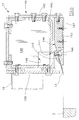
- Figure 1 is a side section schematically showing the means of the invention associated with usual loading carriage of a ceramic mould.
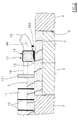
- Figure 2 shows a part of Figure 1 on a larger scale.
- Figure 3 is a view similar to the preceding, showing a modified embodiment of the means for implementing the method of the invention.
- Figure 4 is a schematic view similar to that of Figure 1, showing the means of the invention associated with a loading unit operating in accordance with the double loading technique.
- FIG. 5 is a more detailed section through the surface finishing means of the invention.
- FIGS. 1 to 3 show a usual ceramic mould, indicated overall by the reference numeral 1, comprising a die plate 2 having a single forming cavity 3, a lower die 4 slidingly received within said forming cavity 3, and an upper die 12 carried by the movable crosspiece of a ceramic press, not shown because of known type.
- the mould 1 can have any number of forming cavities 3.
- the die plate 2 and the die 4 are positioned on the bed of the ceramic press by means of known devices able to adjust their height as required.
- Said unit 70 comprises a carriage 9 which is driven with horizontal reciprocating rectilinear movement and is provided at its front with a loading compartment 11 comprising a grid 10.
- the grid 10 can have a lattice configuration different from that shown, as is well known to the expert of the art.
- the carriage 9 and the grid 10 translate between a retracted position in which the grid 10 lies in correspondence with a loading station for the multi-colour powders 7, and an advanced position in which it lies above the cavity 3.
- said amount can be between 0.1 and 4 mm.
- the lower wall 111 can be made to slide vertically to be adjusted in height according to requirements, together with the grid 10. Said adjustment can be made by manual means, such as threaded members, or by automatic means controlled by the general ceramic press control system.
- said finishing unit 17 comprises a horizontal tubular member 14 of right cross-section positioned transversely to the direction of movement of the carriage 9, and having a length exceeding the corresponding dimension of the cavity 3.
- Said tubular member 14 is formed by joining together, using threaded members, a series of flat and profiled elements, which are shown in Figure 5 but need not be described in detail.
- the lower wall of the member 14 provided by the base wall of a channel section indicated by 140, presents on that side facing the front wall 111 of the loading compartment 11, a port 141 having a length at least equal to that dimension of the cavity 3 in the direction in which the carriage 9 slides.
- the front wall 142 of the member 14 extends beyond the base of said channel section 140, where it supports a bracket 143 which extends towards said port 141.
- the bracket 143 terminates with a wide bevel 144 which is inclined downwards towards the wall 111, to projectingly support a surface finishing member 13.
- Said finishing member 13 is locked against said bevel 144 by a clamp device which enables its operating position to be adjusted according to requirements.
- said clamp device comprises an overlying presser plate 145 and an underlying series of clamping screws 146 which pass through the bracket 143 and screw into the presser plate 145.
- the rear region of the presser plate 145 presents along its entire length a bevel facing the port 141 of the tubular member 14.
- At the opposing ends of the bracket 143 there are provided two shoe plates 147 which rest on the upper face of the die plate 2 external to the cavity 3.
- the finishing member 13 comprises a relatively thin elongate plate or lamina positioned perpendicular to the sliding direction of the carriage 9.
- the length of said lamina is greater than the corresponding dimension of the cavity 3, its free longitudinal edge being sharpened. In this respect, it presents along its entire extension a bevel facing the die plate 2 and practically in contact with it.
- the tubular member 14 is closed by two terminal transverse diaphragms 148, at least one of which presents an aperture 149 to which a suction tube 15 (see Figures 1-4) intercepted by a valve 99 is connected.
- Said valve 99 is closed and opened by the outward and return travel strokes of the carriage 9, which are under the control of the overall ceramic press control system for their appropriate adjustments.
- Said tubular member or manifold 14 is connected to the wall 111 of the loading compartment 11 by two end arms 16 by way of a connection and adjustment flange 166 (see Figure 5). Between the lower edge of said flange 166 and the underlying sharp edge of the finishing member 13 there is defined a narrow gap through which atmospheric air is drawn into the manifold 14 to drag with it any dust 7 raised by said sharp edge.
- said two arms 16 are preferably connected to the lateral or side walls of the loading compartment 11.
- the suction tube 15 is connected to an environment able to put the manifold 14 under vacuum, in order to remove the dust 7 which deposits by sliding along the ramp provided by the member 13.
- said manifold 14 and said at least one suction tube 15 can be omitted, and the rear edge of the member 13 be associated with a channel housing a mechanical removal device such as a translating belt or a motorized screw.
- the member 13 and the relative accessories can be relatively close to said wall 111 as shown. If however the loading system of Figure 3 is used, the lower sharp edge of the member 13 must be spaced from the wall 111 by a distance at least equal to that dimension of the cavity 3 in the sliding direction of the carriage 9.
- the member 13 and the respective accessories can be free of the loading compartment 11 and be mounted on an independent drive unit under the control of the ceramic press control system. In that case said unit must be able to determine outward and return travel strokes of length at least equal to that dimension of the cavity 3 in the sliding direction of the carriage 9.
- the aforegiven explanations relative to the operative position of the member 13 are also valid for the double loading system of Figure 4.
- This shows a die plate 2 with relative forming cavity 3; a loading compartment 11 with relative grid 10; a hopper 18 with flow regulator valve 180 operated by a cylinder-piston unit 181 controlled by the ceramic press control system; and a surface finishing unit 17 of the already described type.
- the loading compartment 11 is intended to contain a not particularly valuable powder material 71, i.e. suitable for forming the base or support part of the tile 6, whereas the hopper 18 is intended to contain a finishing material 77, i.e. able to provide the desired aesthetic characteristics for the exposed face of the tile.
- Said finishing material 77 can comprise two powders with different characteristics, typically two differently coloured powder masses at least partially mixed together.
- the lower edges of the loading compartment 11 and grid 10 are coplanar and preferably in line with the upper face of the die plate 2; the lower generators of the discharge port of the hopper 18 are preferably slightly spaced from the die plate 2; and the finishing member 13 is preferably positioned to graze the die plate 2.
- the die 4 On termination of a pressing operation the die 4 lies in its maximum raised position, not shown, where it supports the previously formed tile 6 while awaiting the grid 10.
- the pusher 333 urges the tile 6 onto the conveyor 5, and almost simultaneously the die 4 is brought into the illustrated position in which it frees the upper part of the cavity 3, which fills with multi-colour powder 7.
- Said thin layer is in excess because the quantity of powder 7 required to obtain the desired thickness for the tile 6 is defined by the depth of the cavity 3.
- the finishing member 13 behaves in the manner of a blade which "sweeps" the upper mouth of the cavity 3 to collect the said excessive material. Specifically, the member 13 removes the surface powder layer subjected to scraping and mixing by the lower edges of the grid 10 and wall 111 (see Figure 2), hence displaying the true sharp distribution of the at least two constituent materials of the multi-colour powder 7.
- the material collected by the member 13 is removed continuously by applying suitable suction to the manifold 14.
- the lower die 4 firstly moves into its maximum lowered or pressing position, then the upper die 12 is lowered to form the tile 6, and finally the two dies 12 and 4 are raised nearly simultaneously, with the first 12 assuming the position shown in Figure 1 and the second 4 lying flush with the die plate 2 to offer the tile 6 to the pusher 333.
- the grid 10 and loading compartment 11 are practically in contact with the upper face of the table 8, and the multi-colour powder 7 is completely contained within the cavity 3 before the operation of the finishing member 13.
- the die 4 is lowered by a distance equal to the thickness of the powder intended to form the tile 6 plus the thickness of the excess surface layer, said surface layer being flush with the loading compartment 11.
- the said lowered position of the die 4 is indicated in Figure 3 by 991.
- a first mode consists of raising the die 4, after passage of the loading compartment 11 but before the arrival of the member 13, by a distance equal to the thickness of said surface layer, to make it available to the member 13 ( Figure 3).
- the second mode consists of lowering the die plate 2 by a distance equal to the thickness of said surface layer of powder 7, said lowering occurring preferably after the wall 111 of the loading compartment 11 has reached the operating table 8.
- finishing member 13 is supported by its own drive unit by way of means which enable it to slide vertically. This is to enable it to rest on the die plate 2 when in the lowered position.
- Said vertical sliding can be obtained either by automatic means or more simply by gravity.
- a processor 888 which is connected to the overall press control system to synchronously control the said vertical movements of the die 4 and die plate 2 in accordance with the two operative modes described with reference to Figure 3.
- a third loading mode for the cavity 3 is possible, consisting of maintaining the die 4 in the position shown by continuous lines in Figure 3, and raising the combined loading compartment and grid 11-10 during the retraction of the carriage 9. Specifically, said combination 11-10 is spaced from the die plate 2 by an amount equal to the thickness of said surface layer and, once the wall 111 has passed beyond the cavity 3, the combination 11-10 is again lowered into its starting position. The surface layer of multi-colour powder 7 is removed as previously.
- the die 4 With the loading system of Figure 4, during the return travel of the carriage 9 the die 4 becomes positioned at two different levels. When the die 4 occupies the higher level, the loading compartment 11 deposits into the cavity 3 the required quantity of base material 71, which is scraped by the wall 111.
- the active face of the upper die 12 can be smooth or be relief contoured for the reasons explained in the introduction.
Landscapes
- Engineering & Computer Science (AREA)
- Manufacturing & Machinery (AREA)
- Chemical & Material Sciences (AREA)
- Ceramic Engineering (AREA)
- Mechanical Engineering (AREA)
- Press-Shaping Or Shaping Using Conveyers (AREA)
- Devices For Post-Treatments, Processing, Supply, Discharge, And Other Processes (AREA)
- Moulds, Cores, Or Mandrels (AREA)
Abstract
Description
Claims (27)
- A method for loading ceramic moulds presenting a die plate having at least one forming cavity in which a die is slidingly received, comprising the following operative steps for each complete loading cycle:characterised by comprising the following operative stages:preparing a powder layer at least the upper part of which has properties conforming to the required aesthetic characteristics of the exposed face of the tile, andtransferring said layer to above said at least one forming cavity,depositing into said at least one cavity a powder layer having a thickness greater than that necessary to obtain the desired tile thickness, andbefore pressing removing, by a mechanical cutting action with simultaneous removal of the thus separated material, the surface layer of the powder contained in the mould cavity, without appreciable mixing of the powder present at the interface between the surface layer and the underlying layer.
- A method as claimed in claim 1, characterised in that said surface layer is created above the plane defined by the upper edge of said at least one forming cavity.
- A method as claimed in claim 1, characterised in that said surface layer is created in the interior of said at least one forming cavity, flush with its upper edge.
- A method as claimed in claim 3, characterised in that prior to said removal, said surface layer is raised beyond the upper surface of said at least one forming cavity.
- A method as claimed in claim 4, characterised in that said raising is achieved by upwardly sliding the die relative to said at least one forming cavity.
- A method as claimed in claim 4, characterised in that said raising is achieved by downwardly sliding the die plate relative to the die.
- A plant for loading ceramic moulds provided with forming cavities, comprising a loading carriage presenting a loading compartment provided with a grid for retaining the powders, and driven with horizontal reciprocating rectilinear movement between a retracted position in which it disposes the grid below at least one hopper for supplying a mass of ceramic powder, and an advanced position in which it disposes the grid above the forming cavity of a mould, characterised by comprising a movable implement which is arranged to translate along said forming cavity, and presents a finishing member positioned a short distance from the upper edge of said forming cavity in order, before pressing, to remove a small upper surface layer of powder without any mixing.
- A plant as claimed in claim 7, characterised by comprising means for creating, in correspondence with said forming cavity, a powder layer exceeding that necessary for obtaining the required tile thickness.
- A plant as claimed in claim 8, characterised in that the excess powder layer has a thickness of 0.1-4 mm.
- A plant as claimed in claim 8, characterised in that said means are shaped in such a manner as to dispose said excess layer beyond the upper edge of said forming cavity.
- A plant as claimed in claim 10, characterised in that said means are provided by the front transverse wall of the loading compartment and of the grid.
- A plant as claimed in claim 11, characterised in that said front wall and said grid are adjustable in height.
- A plant as claimed in claim 12, characterised in that said height adjustment is achieved by manual means.
- A plant as claimed in claim 10, characterised in that said means are provided by the combination of the loading compartment and grid, said combination having its lower edges positioned in the same plane and being connected to the respective support structure by a unit able to vary its position in height relative to the die plate.
- A plant as claimed in claim 8, characterised in that said means are means for raising the die contained in said forming cavity.
- A plant as claimed in claim 8, characterised in that said means are means that lower the die plate defining said forming cavity.
- A plant as claimed in claim 7, characterised in that said finishing member consists of relatively thin flat elongate body positioned transversely to the direction of movement of the carriage and having a length greater than the corresponding dimension of said at least one cavity, it being transversely inclined to define, with the mouth of said at least one cavity, an angle with its vertex facing the carriage, the lower edge of said body presenting along its entire extension a bevel which is virtually parallel to the mould die plate.
- A plant as claimed in claim 17, characterised in that means are associated with the upper edge of said body to remove the powder raised by the body.
- A plant as claimed in claim 18, characterised in that said removal means comprise a manifold which presents a suction port close to the upper edge of said body, and is connected to a vacuum environment.
- A plant as claimed in claim 19, characterised in that the connection between said port and said vacuum environment is intercepted by a valve member arranged to close and open synchronously with the outward and return movement of the carriage.
- A plant as claimed in claim 18, characterised in that said removal means comprise a channel situated behind the upper edge of said body and presenting in its bottom part a conveyor means such as a belt or a motorized screw.
- A plant as claimed in claim 7, characterised in that said movable implement is rigid with said carriage.
- A plant as claimed in claim 7, characterised in that between said loading compartment and said finishing member there is interposed a powder-containing hopper, the discharge port of which is positioned a short distance from the die plate and is intercepted by a flow regulator valve.
- A plant as claimed in claim 7, characterised in that said finishing member is spaced from the loading compartment by an amount at least equal to that dimension of the forming cavity in the carriage travel direction.
- A plant as claimed in claim 23, characterised in that said finishing member is spaced from said hopper by an amount at least equal to that dimension of the forming cavity in the carriage travel direction.
- A plant as claimed in claim 7, characterised in that said finishing member is slidingly carried by said movable implement and is controlled by a control unit arranged to cause it to slide forwards and backwards by an amount at least equal to that dimension of the forming cavity in the carriage travel direction.
- A plant as claimed in claim 7, characterised in that said finishing member is supported by said movable implement by way of interposed means enabling it to be adjusted in height.
Applications Claiming Priority (2)
| Application Number | Priority Date | Filing Date | Title |
|---|---|---|---|
| ITRE20010072 | 2001-07-05 | ||
| IT2001RE000072A ITRE20010072A1 (en) | 2001-07-05 | 2001-07-05 | METHOD FOR LOADING THE CERAMIC MOLDS OF FORMING THE TILES, IMPLANT FOR ITS IMPLEMENTATION, AND TILES OBTAINED WITH DET |
Publications (3)
| Publication Number | Publication Date |
|---|---|
| EP1273409A2 true EP1273409A2 (en) | 2003-01-08 |
| EP1273409A3 EP1273409A3 (en) | 2004-06-23 |
| EP1273409B1 EP1273409B1 (en) | 2007-09-19 |
Family
ID=11454130
Family Applications (1)
| Application Number | Title | Priority Date | Filing Date |
|---|---|---|---|
| EP02077415A Expired - Lifetime EP1273409B1 (en) | 2001-07-05 | 2002-06-18 | Method for loading ceramic tile forming moulds, plant for its implementation, and tiles obtained thereby |
Country Status (9)
| Country | Link |
|---|---|
| US (1) | US6684913B2 (en) |
| EP (1) | EP1273409B1 (en) |
| CN (1) | CN1221365C (en) |
| AT (1) | ATE373551T1 (en) |
| DE (1) | DE60222501T2 (en) |
| ES (1) | ES2292688T3 (en) |
| IT (1) | ITRE20010072A1 (en) |
| MX (2) | MXPA02006633A (en) |
| PT (1) | PT1273409E (en) |
Cited By (5)
| Publication number | Priority date | Publication date | Assignee | Title |
|---|---|---|---|---|
| WO2003051593A1 (en) | 2001-12-18 | 2003-06-26 | Mirage Granito Ceramico S.P.A. | System of feeding a ceramic press for forming ceramic items |
| WO2005025829A1 (en) * | 2003-09-15 | 2005-03-24 | Sacmi Cooperativa Meccanici Imola Societa' Cooperativa | Method and plant for forming ceramic tiles or slabs |
| ITRN20120039A1 (en) * | 2012-07-31 | 2014-02-01 | Rp S R L | APPARATUS AND METHODS OF SUPPLY OF MOLDS PRESSED IN MULTILAYER TILES OR SIMILAR PRODUCTS. |
| CN104772817A (en) * | 2015-04-16 | 2015-07-15 | 佛山市简一陶瓷有限公司 | Distributing system for producing full-body marble tile |
| IT201900003663A1 (en) * | 2019-03-13 | 2020-09-13 | Davide Maternini S P A | EQUIPMENT FOR MANUFACTURING ABRASIVE DISCS AND RELATIVE METHOD |
Families Citing this family (9)
| Publication number | Priority date | Publication date | Assignee | Title |
|---|---|---|---|---|
| ITRE20010073A1 (en) * | 2001-07-05 | 2003-01-05 | Sacmi | METHOD FOR LOADING THE CERAMIC MOLDS FOR FORMING THE TILES, RELATED MEANS OF IMPLEMENTATION, AND TILES OBTAINED WITH THE SAID |
| WO2005068143A1 (en) * | 2003-10-29 | 2005-07-28 | Jimian Chen | Multi-pipes material-distributing equipment for compacting tiles and its distributing method |
| US20100310695A1 (en) * | 2009-06-03 | 2010-12-09 | Keystone Retaining Wall Systems, Inc. | Floating cut-off bar and method of use thereof |
| WO2010141705A1 (en) * | 2009-06-03 | 2010-12-09 | Keystone Retaining Wall Systems, Inc. | Floating cut-off bar for a mold box |
| DE102011050367B4 (en) * | 2011-05-13 | 2012-12-20 | Rekers Verwaltungs-GmbH & Co. KG | Shaking grate for a filling car of a stone forming machine |
| US20180339622A1 (en) * | 2015-05-06 | 2018-11-29 | Schukra Gerätebau Gmbh | System and method of controlling fibers in a mold |
| DE102016121594A1 (en) * | 2016-11-10 | 2018-05-17 | Fraunhofer-Gesellschaft zur Förderung der angewandten Forschung e.V. | METHOD FOR IMPROVING THE SURFACE QUALITY OF GENERATIVELY PRODUCED COMPONENTS |
| CN107379232A (en) * | 2017-06-09 | 2017-11-24 | 信益陶瓷(中国)有限公司 | A kind of entire body marble ceramic tile blank moulding process |
| US10280634B1 (en) * | 2018-08-30 | 2019-05-07 | Jorge P Remos | Product leveling device for tile machines |
Family Cites Families (5)
| Publication number | Priority date | Publication date | Assignee | Title |
|---|---|---|---|---|
| SE427815B (en) * | 1980-02-29 | 1983-05-09 | Abece Ab | MACHINE FOR THE CONSTRUCTION OF CONCRETE PANELS |
| GB2277707B (en) * | 1993-04-29 | 1996-07-03 | Redland Technology Ltd | Improvements in a roof tile making machine |
| US6213168B1 (en) * | 1997-03-31 | 2001-04-10 | Therics, Inc. | Apparatus and method for dispensing of powders |
| IT1310965B1 (en) * | 1999-08-02 | 2002-02-27 | Lb Officine Meccaniche Spa | EQUIPMENT FOR LOADING THE MATERIAL IN THE CAVITY OF THE AMATEUR OF A MOLD, IN PARTICULAR, FOR PRESSING TILES |
| ITMO20010253A1 (en) * | 2001-12-18 | 2003-06-18 | Mirage Granito Ceramico Spa | FEEDING SYSTEM OF A PRESS FOR THE FORMING OF CERAMIC OBJECTS |
-
2001
- 2001-07-05 IT IT2001RE000072A patent/ITRE20010072A1/en unknown
-
2002
- 2002-06-18 PT PT02077415T patent/PT1273409E/en unknown
- 2002-06-18 EP EP02077415A patent/EP1273409B1/en not_active Expired - Lifetime
- 2002-06-18 DE DE60222501T patent/DE60222501T2/en not_active Expired - Fee Related
- 2002-06-18 ES ES02077415T patent/ES2292688T3/en not_active Expired - Lifetime
- 2002-06-18 AT AT02077415T patent/ATE373551T1/en not_active IP Right Cessation
- 2002-06-25 CN CNB021233934A patent/CN1221365C/en not_active Expired - Fee Related
- 2002-07-03 MX MXPA02006633A patent/MXPA02006633A/en active IP Right Grant
- 2002-07-03 MX MXPA02006634A patent/MXPA02006634A/en active IP Right Grant
- 2002-07-05 US US10/189,254 patent/US6684913B2/en not_active Expired - Fee Related
Cited By (5)
| Publication number | Priority date | Publication date | Assignee | Title |
|---|---|---|---|---|
| WO2003051593A1 (en) | 2001-12-18 | 2003-06-26 | Mirage Granito Ceramico S.P.A. | System of feeding a ceramic press for forming ceramic items |
| WO2005025829A1 (en) * | 2003-09-15 | 2005-03-24 | Sacmi Cooperativa Meccanici Imola Societa' Cooperativa | Method and plant for forming ceramic tiles or slabs |
| ITRN20120039A1 (en) * | 2012-07-31 | 2014-02-01 | Rp S R L | APPARATUS AND METHODS OF SUPPLY OF MOLDS PRESSED IN MULTILAYER TILES OR SIMILAR PRODUCTS. |
| CN104772817A (en) * | 2015-04-16 | 2015-07-15 | 佛山市简一陶瓷有限公司 | Distributing system for producing full-body marble tile |
| IT201900003663A1 (en) * | 2019-03-13 | 2020-09-13 | Davide Maternini S P A | EQUIPMENT FOR MANUFACTURING ABRASIVE DISCS AND RELATIVE METHOD |
Also Published As
| Publication number | Publication date |
|---|---|
| DE60222501T2 (en) | 2008-01-10 |
| EP1273409B1 (en) | 2007-09-19 |
| US6684913B2 (en) | 2004-02-03 |
| ITRE20010072A0 (en) | 2001-07-05 |
| PT1273409E (en) | 2007-12-27 |
| MXPA02006634A (en) | 2004-08-19 |
| US20030006525A1 (en) | 2003-01-09 |
| MXPA02006633A (en) | 2004-08-19 |
| EP1273409A3 (en) | 2004-06-23 |
| ES2292688T3 (en) | 2008-03-16 |
| ITRE20010072A1 (en) | 2003-01-05 |
| CN1396046A (en) | 2003-02-12 |
| ATE373551T1 (en) | 2007-10-15 |
| DE60222501D1 (en) | 2007-10-31 |
| CN1221365C (en) | 2005-10-05 |
Similar Documents
| Publication | Publication Date | Title |
|---|---|---|
| US6684913B2 (en) | Method for loading ceramic tile forming moulds, plant for its implementation, and tiles obtained thereby | |
| EP1273408B1 (en) | Method for loading ceramic tile forming moulds, relative means for its implementation, and tiles obtained thereby | |
| CN1906001B (en) | Method and apparatus for pre-arranging powder to form tiles or slabs | |
| US3627861A (en) | Method of forming indented decorative patterns on ceramic tile | |
| WO2005090034A1 (en) | Method and plant for preparing a layer of powders to be pressed to obtain ceramic tiles | |
| CN100493875C (en) | Method and apparatus for forming ceramic tiles or slabs | |
| JPH0242599B2 (en) | ||
| US7267536B2 (en) | Apparatus for forming large-dimension ceramic tiles | |
| EP0569070B1 (en) | Mold for forming ceramic products, tipically pressure-glazed tiles, and the relative loading means | |
| WO2005025829B1 (en) | Method and plant for forming ceramic tiles or slabs | |
| CN207983659U (en) | It is a kind of to scrape benefit apparatus for distributing for the production of true entire body ceramic tile | |
| EP1211034A2 (en) | Tile press with belt charging devices | |
| WO2002007939A1 (en) | System for feeding a ceramic press | |
| EP1256428A2 (en) | Method for loading ceramic tile forming moulds, a plant for its implementation, and tiles obtained thereby | |
| CN1727145A (en) | Technique for molding adobe of ceramic brick | |
| EP1323510A1 (en) | Ceramic double-loading carriage | |
| EP1305149A1 (en) | Unit and method for loading the mould cavity with powder or granular material, in ceramic tile manufacture | |
| EP1458533B1 (en) | System and method of feeding a ceramic press for forming ceramic items | |
| EP0569069B1 (en) | Ceramic mold for forming tiles, and the relative loading means | |
| US2392399A (en) | Apparatus for use in manufacturing pottery ware | |
| EP1225016A2 (en) | Method for loading ceramic tile forming moulds, relative means for its implementation, and tiles obtained thereby | |
| KR830000119B1 (en) | Roof Tile Forming Apparatus | |
| EP1773553A1 (en) | Plant for feeding a double layer of powder or granular material into the cavity of the mould for ceramic tile production | |
| CN1820920A (en) | Method for producing artificial marble ceramic glazed tile and its producing device |
Legal Events
| Date | Code | Title | Description |
|---|---|---|---|
| PUAI | Public reference made under article 153(3) epc to a published international application that has entered the european phase |
Free format text: ORIGINAL CODE: 0009012 |
|
| AK | Designated contracting states |
Kind code of ref document: A2 Designated state(s): AT BE CH CY DE DK ES FI FR GB GR IE IT LI LU MC NL PT SE TR |
|
| AX | Request for extension of the european patent |
Free format text: AL;LT;LV;MK;RO;SI |
|
| PUAL | Search report despatched |
Free format text: ORIGINAL CODE: 0009013 |
|
| AK | Designated contracting states |
Kind code of ref document: A3 Designated state(s): AT BE CH CY DE DK ES FI FR GB GR IE IT LI LU MC NL PT SE TR |
|
| AX | Request for extension of the european patent |
Extension state: AL LT LV MK RO SI |
|
| 17P | Request for examination filed |
Effective date: 20041108 |
|
| AKX | Designation fees paid |
Designated state(s): AT BE CH CY DE DK ES FI FR GB GR IE IT LI LU MC NL PT SE TR |
|
| 17Q | First examination report despatched |
Effective date: 20050408 |
|
| RAP1 | Party data changed (applicant data changed or rights of an application transferred) |
Owner name: SACMI COOPERATIVA MECCANICI IMOLA SOCIETA' COOPERA |
|
| RIC1 | Information provided on ipc code assigned before grant |
Ipc: B28B 13/02 20060101AFI20070302BHEP Ipc: B30B 15/30 20060101ALI20070302BHEP |
|
| GRAP | Despatch of communication of intention to grant a patent |
Free format text: ORIGINAL CODE: EPIDOSNIGR1 |
|
| GRAS | Grant fee paid |
Free format text: ORIGINAL CODE: EPIDOSNIGR3 |
|
| GRAA | (expected) grant |
Free format text: ORIGINAL CODE: 0009210 |
|
| AK | Designated contracting states |
Kind code of ref document: B1 Designated state(s): AT BE CH CY DE DK ES FI FR GB GR IE IT LI LU MC NL PT SE TR |
|
| REG | Reference to a national code |
Ref country code: GB Ref legal event code: FG4D |
|
| REG | Reference to a national code |
Ref country code: CH Ref legal event code: EP |
|
| REF | Corresponds to: |
Ref document number: 60222501 Country of ref document: DE Date of ref document: 20071031 Kind code of ref document: P |
|
| REG | Reference to a national code |
Ref country code: IE Ref legal event code: FG4D |
|
| REG | Reference to a national code |
Ref country code: PT Ref legal event code: SC4A Free format text: AVAILABILITY OF NATIONAL TRANSLATION Effective date: 20071217 |
|
| PG25 | Lapsed in a contracting state [announced via postgrant information from national office to epo] |
Ref country code: FI Free format text: LAPSE BECAUSE OF FAILURE TO SUBMIT A TRANSLATION OF THE DESCRIPTION OR TO PAY THE FEE WITHIN THE PRESCRIBED TIME-LIMIT Effective date: 20070919 |
|
| PG25 | Lapsed in a contracting state [announced via postgrant information from national office to epo] |
Ref country code: LI Free format text: LAPSE BECAUSE OF FAILURE TO SUBMIT A TRANSLATION OF THE DESCRIPTION OR TO PAY THE FEE WITHIN THE PRESCRIBED TIME-LIMIT Effective date: 20070919 Ref country code: AT Free format text: LAPSE BECAUSE OF FAILURE TO SUBMIT A TRANSLATION OF THE DESCRIPTION OR TO PAY THE FEE WITHIN THE PRESCRIBED TIME-LIMIT Effective date: 20070919 Ref country code: CH Free format text: LAPSE BECAUSE OF FAILURE TO SUBMIT A TRANSLATION OF THE DESCRIPTION OR TO PAY THE FEE WITHIN THE PRESCRIBED TIME-LIMIT Effective date: 20070919 |
|
| NLV1 | Nl: lapsed or annulled due to failure to fulfill the requirements of art. 29p and 29m of the patents act | ||
| REG | Reference to a national code |
Ref country code: ES Ref legal event code: FG2A Ref document number: 2292688 Country of ref document: ES Kind code of ref document: T3 |
|
| PG25 | Lapsed in a contracting state [announced via postgrant information from national office to epo] |
Ref country code: BE Free format text: LAPSE BECAUSE OF FAILURE TO SUBMIT A TRANSLATION OF THE DESCRIPTION OR TO PAY THE FEE WITHIN THE PRESCRIBED TIME-LIMIT Effective date: 20070919 |
|
| REG | Reference to a national code |
Ref country code: CH Ref legal event code: PL |
|
| PG25 | Lapsed in a contracting state [announced via postgrant information from national office to epo] |
Ref country code: GR Free format text: LAPSE BECAUSE OF FAILURE TO SUBMIT A TRANSLATION OF THE DESCRIPTION OR TO PAY THE FEE WITHIN THE PRESCRIBED TIME-LIMIT Effective date: 20071220 Ref country code: NL Free format text: LAPSE BECAUSE OF FAILURE TO SUBMIT A TRANSLATION OF THE DESCRIPTION OR TO PAY THE FEE WITHIN THE PRESCRIBED TIME-LIMIT Effective date: 20070919 |
|
| EN | Fr: translation not filed | ||
| PG25 | Lapsed in a contracting state [announced via postgrant information from national office to epo] |
Ref country code: SE Free format text: LAPSE BECAUSE OF FAILURE TO SUBMIT A TRANSLATION OF THE DESCRIPTION OR TO PAY THE FEE WITHIN THE PRESCRIBED TIME-LIMIT Effective date: 20071219 |
|
| PLBE | No opposition filed within time limit |
Free format text: ORIGINAL CODE: 0009261 |
|
| STAA | Information on the status of an ep patent application or granted ep patent |
Free format text: STATUS: NO OPPOSITION FILED WITHIN TIME LIMIT |
|
| PG25 | Lapsed in a contracting state [announced via postgrant information from national office to epo] |
Ref country code: DK Free format text: LAPSE BECAUSE OF FAILURE TO SUBMIT A TRANSLATION OF THE DESCRIPTION OR TO PAY THE FEE WITHIN THE PRESCRIBED TIME-LIMIT Effective date: 20070919 |
|
| PGFP | Annual fee paid to national office [announced via postgrant information from national office to epo] |
Ref country code: ES Payment date: 20080523 Year of fee payment: 7 |
|
| 26N | No opposition filed |
Effective date: 20080620 |
|
| PG25 | Lapsed in a contracting state [announced via postgrant information from national office to epo] |
Ref country code: FR Free format text: LAPSE BECAUSE OF FAILURE TO SUBMIT A TRANSLATION OF THE DESCRIPTION OR TO PAY THE FEE WITHIN THE PRESCRIBED TIME-LIMIT Effective date: 20080523 |
|
| PGFP | Annual fee paid to national office [announced via postgrant information from national office to epo] |
Ref country code: IT Payment date: 20080626 Year of fee payment: 7 Ref country code: PT Payment date: 20080526 Year of fee payment: 7 |
|
| PGFP | Annual fee paid to national office [announced via postgrant information from national office to epo] |
Ref country code: DE Payment date: 20080621 Year of fee payment: 7 |
|
| PG25 | Lapsed in a contracting state [announced via postgrant information from national office to epo] |
Ref country code: MC Free format text: LAPSE BECAUSE OF NON-PAYMENT OF DUE FEES Effective date: 20080630 |
|
| GBPC | Gb: european patent ceased through non-payment of renewal fee |
Effective date: 20080618 |
|
| PG25 | Lapsed in a contracting state [announced via postgrant information from national office to epo] |
Ref country code: IE Free format text: LAPSE BECAUSE OF NON-PAYMENT OF DUE FEES Effective date: 20080618 |
|
| PG25 | Lapsed in a contracting state [announced via postgrant information from national office to epo] |
Ref country code: GB Free format text: LAPSE BECAUSE OF NON-PAYMENT OF DUE FEES Effective date: 20080618 |
|
| PG25 | Lapsed in a contracting state [announced via postgrant information from national office to epo] |
Ref country code: CY Free format text: LAPSE BECAUSE OF FAILURE TO SUBMIT A TRANSLATION OF THE DESCRIPTION OR TO PAY THE FEE WITHIN THE PRESCRIBED TIME-LIMIT Effective date: 20070919 |
|
| REG | Reference to a national code |
Ref country code: PT Ref legal event code: MM4A Free format text: LAPSE DUE TO NON-PAYMENT OF FEES Effective date: 20091218 |
|
| PG25 | Lapsed in a contracting state [announced via postgrant information from national office to epo] |
Ref country code: PT Free format text: LAPSE BECAUSE OF NON-PAYMENT OF DUE FEES Effective date: 20091218 |
|
| PG25 | Lapsed in a contracting state [announced via postgrant information from national office to epo] |
Ref country code: DE Free format text: LAPSE BECAUSE OF NON-PAYMENT OF DUE FEES Effective date: 20100101 |
|
| PG25 | Lapsed in a contracting state [announced via postgrant information from national office to epo] |
Ref country code: LU Free format text: LAPSE BECAUSE OF NON-PAYMENT OF DUE FEES Effective date: 20080618 |
|
| REG | Reference to a national code |
Ref country code: ES Ref legal event code: FD2A Effective date: 20090619 |
|
| PG25 | Lapsed in a contracting state [announced via postgrant information from national office to epo] |
Ref country code: TR Free format text: LAPSE BECAUSE OF FAILURE TO SUBMIT A TRANSLATION OF THE DESCRIPTION OR TO PAY THE FEE WITHIN THE PRESCRIBED TIME-LIMIT Effective date: 20070919 |
|
| PG25 | Lapsed in a contracting state [announced via postgrant information from national office to epo] |
Ref country code: ES Free format text: LAPSE BECAUSE OF NON-PAYMENT OF DUE FEES Effective date: 20090619 |
|
| PG25 | Lapsed in a contracting state [announced via postgrant information from national office to epo] |
Ref country code: IT Free format text: LAPSE BECAUSE OF NON-PAYMENT OF DUE FEES Effective date: 20090618 |