EP1273373B1 - Outil rotatif avec tête de coupe remplaçable - Google Patents
Outil rotatif avec tête de coupe remplaçable Download PDFInfo
- Publication number
- EP1273373B1 EP1273373B1 EP02445070A EP02445070A EP1273373B1 EP 1273373 B1 EP1273373 B1 EP 1273373B1 EP 02445070 A EP02445070 A EP 02445070A EP 02445070 A EP02445070 A EP 02445070A EP 1273373 B1 EP1273373 B1 EP 1273373B1
- Authority
- EP
- European Patent Office
- Prior art keywords
- cutting head
- tool
- seat
- shaft
- support surface
- Prior art date
- Legal status (The legal status is an assumption and is not a legal conclusion. Google has not performed a legal analysis and makes no representation as to the accuracy of the status listed.)
- Expired - Lifetime
Links
Images


Classifications
-
- B—PERFORMING OPERATIONS; TRANSPORTING
- B23—MACHINE TOOLS; METAL-WORKING NOT OTHERWISE PROVIDED FOR
- B23B—TURNING; BORING
- B23B51/00—Tools for drilling machines
- B23B51/02—Twist drills
-
- B—PERFORMING OPERATIONS; TRANSPORTING
- B23—MACHINE TOOLS; METAL-WORKING NOT OTHERWISE PROVIDED FOR
- B23B—TURNING; BORING
- B23B2205/00—Fixation of cutting inserts in holders
- B23B2205/02—Fixation using an elastically deformable clamping member
-
- B—PERFORMING OPERATIONS; TRANSPORTING
- B23—MACHINE TOOLS; METAL-WORKING NOT OTHERWISE PROVIDED FOR
- B23B—TURNING; BORING
- B23B2251/00—Details of tools for drilling machines
- B23B2251/02—Connections between shanks and removable cutting heads
-
- Y—GENERAL TAGGING OF NEW TECHNOLOGICAL DEVELOPMENTS; GENERAL TAGGING OF CROSS-SECTIONAL TECHNOLOGIES SPANNING OVER SEVERAL SECTIONS OF THE IPC; TECHNICAL SUBJECTS COVERED BY FORMER USPC CROSS-REFERENCE ART COLLECTIONS [XRACs] AND DIGESTS
- Y10—TECHNICAL SUBJECTS COVERED BY FORMER USPC
- Y10S—TECHNICAL SUBJECTS COVERED BY FORMER USPC CROSS-REFERENCE ART COLLECTIONS [XRACs] AND DIGESTS
- Y10S408/00—Cutting by use of rotating axially moving tool
- Y10S408/713—Tool having detachable cutting edge
-
- Y—GENERAL TAGGING OF NEW TECHNOLOGICAL DEVELOPMENTS; GENERAL TAGGING OF CROSS-SECTIONAL TECHNOLOGIES SPANNING OVER SEVERAL SECTIONS OF THE IPC; TECHNICAL SUBJECTS COVERED BY FORMER USPC CROSS-REFERENCE ART COLLECTIONS [XRACs] AND DIGESTS
- Y10—TECHNICAL SUBJECTS COVERED BY FORMER USPC
- Y10T—TECHNICAL SUBJECTS COVERED BY FORMER US CLASSIFICATION
- Y10T408/00—Cutting by use of rotating axially moving tool
- Y10T408/03—Processes
-
- Y—GENERAL TAGGING OF NEW TECHNOLOGICAL DEVELOPMENTS; GENERAL TAGGING OF CROSS-SECTIONAL TECHNOLOGIES SPANNING OVER SEVERAL SECTIONS OF THE IPC; TECHNICAL SUBJECTS COVERED BY FORMER USPC CROSS-REFERENCE ART COLLECTIONS [XRACs] AND DIGESTS
- Y10—TECHNICAL SUBJECTS COVERED BY FORMER USPC
- Y10T—TECHNICAL SUBJECTS COVERED BY FORMER US CLASSIFICATION
- Y10T408/00—Cutting by use of rotating axially moving tool
- Y10T408/78—Tool of specific diverse material
-
- Y—GENERAL TAGGING OF NEW TECHNOLOGICAL DEVELOPMENTS; GENERAL TAGGING OF CROSS-SECTIONAL TECHNOLOGIES SPANNING OVER SEVERAL SECTIONS OF THE IPC; TECHNICAL SUBJECTS COVERED BY FORMER USPC CROSS-REFERENCE ART COLLECTIONS [XRACs] AND DIGESTS
- Y10—TECHNICAL SUBJECTS COVERED BY FORMER USPC
- Y10T—TECHNICAL SUBJECTS COVERED BY FORMER US CLASSIFICATION
- Y10T408/00—Cutting by use of rotating axially moving tool
- Y10T408/89—Tool or Tool with support
- Y10T408/909—Having peripherally spaced cutting edges
- Y10T408/9095—Having peripherally spaced cutting edges with axially extending relief channel
- Y10T408/9097—Spiral channel
Definitions
- the present invention relates to a rotatable tool having a replaceable cutting head at the chip removing, free end of the tool, whereby the tool also comprises a shaft defining a longitudinal axis of rotation and having a seat, in which the cutting head is intended to be received, the shaft having members with the help of which chips generated by the cutting head can be transported away, the cutting head having members for chip removing machining, preferably of metal, the seat and the replaceable cutting head having mutually co-operating portions/surfaces , which extend essentially both in the longitudinal direction of the tool and transverse to the longitudinal direction of the tool, the cutting head being positionable in an attached state in response to a relative movement between the cutting head and the shaft in one direction about the longitudinal axis, and positionable out of the attached state in response to a relative rotation between the cutting head and the shaft in an opposite direction about the longitudinal axis, at least a first support surface of the seat, and at least a second support surface of the cutting head, providing both fixing of the cutting head in the axial direction of the
- a rotatable tool for chip forming machining having a replaceable cutting head, which is assembled on a shaft of the tool by means of a type of bayonet coupling is previously know from US-A-5,957,631 .
- the replaceable cutting head and the shaft of the tool have co-operating surfaces for transmission of torque, as well as fixing walls which form a dovetail joint when the cutting head is assembled on the shaft.
- a tool,a cutting part and a tool body for chip forming machining as well as a method for mounting the cutting part onto the tool body are previously known from US-A-5,988,953 .
- the cutting part is assembled onto the tool body by means of a bayonet coupling.
- a primary aim of the present invention is to describe a rotatable tool of the kind defined above, where the surfaces for the transferring of torque at the same time serve as surfaces for fixing the replaceable cutting head in the axial direction. Thereby, a replaceable cutting head having a relatively small extension in the axial direction is obtained.
- Another aim of the present invention is that the fixation of the replaceable cutting head is carried out by a so-called snap function.
- Yet another aim of the invention is that portions of the seat are actuated by a force directed towards the centre of the tool in an embodiment of the same. Thereby, an improved clamping of the cutting head in the seat is obtained.
- Another aim of the present invention is to provide a satisfactory cooling of the cutting head, especially in regard to the front surface thereof.
- the cutting head should be given such geometry that it is relatively simple to manufacture, for instance by pressing, if it is made from cemented carbide.
- the twist drill comprises a shaft 1 as well as a replaceable cutting head 3 assembled on the shaft.
- the shaft 1 is provided with two chip channels 5 for removing the chips, which are generated when the cutting head 3 machines a workpiece. Only one of the chip channels 5 is visible in Fig 1 .
- the twist drill also comprises in a conventional way a fastening part (not shown), which is intended to be attached in a chuck or the like of a machine tool.
- a seat 7 arranged in the shaft 1 is shown more in detail, whereby the seat 7 is arranged at the end of the shaft 1 that is turned from the fastening part.
- the seat 7 of the shaft 1 comprises a plurality of different surfaces, which shall co-operate in order to give a satisfactory support to the replaceable cutting head 3 in an optimum way when the same is assembled in the seat 7.
- the cutting seat comprises a bottom surface 9 as well as two sidewalls 10, arranged diametrically in respect of the shaft 1, in the end surfaces of which port cooling ducts 11.
- the surfaces of the side walls 10 which are turned towards each other are generally composed of convex and concave portions, whereby said portions have an axial extension which is parallel to the axial direction of the shaft 1.
- the sidewalls 10 have a central first convex portion 12, which is surrounded on both sides by a first and a second concave portion 13 and 14, respectively.
- the sidewalls 10 On the side of the first concave portion 13, which is turned from the first convex portion 12, the sidewalls 10 have a second convex portion 15.
- a first support surface 16 connects with the second convex portion 15, whereby the first support surface 16 generally has an extension inwards towards the centre of the tool.
- said first support surface 16 has an inclination in the axial direction, the importance of which will be closer explained below in connection with the interaction between the seat 7 and the replaceable cutting head 3 being described.
- the first support surface 16 has such an inclination in the axial direction that the planes which are defined by said support surface 16 and the bottom surface 9 form an angle with each other which is smaller than 90°.
- the extension inwards towards the centre of the first support surface 16 it should be pointed out that the extension thereof does not pass through the centre of the twist drill. The significance of this will be illustrated more closely below.
- the engagement surfaces 20 are generally composed of convex and concave portions, whereby said portions have an axial extension which is parallel to the axial direction of the shaft 1 when the cutting head 3 is assembled in the seat 7.
- the engagement surfaces 20 comprise a centrally located third concave portion 21, which is intended to co-operate with the first convex portion 12 of the side walls 10.
- the engagement surfaces 20 have a third convex portion 22, which is intended to be located exactly opposite the first concave portion 13 of the side walls 10.
- the engagement surfaces 20 have a fourth concave portion 23, which is intended to be located exactly opposite the second convex portion 15 of the side walls 10.
- the engagement surfaces have a second support surface 24, which is intended to co-operate with the first support surface 16 of the side walls 10, and which extends to a forwardly facing front surface 24a of the cutting head.
- the second support surface 24 has generally an extension inwards towards the centre when the cutting head 3 is assembled in the seat 7.
- the engagement surfaces 20 have a fifth concave portion 25, which in the assembled position of the cutting head 3 is located exactly opposite the central part of the second concave portion 14.
- the engagement surfaces 20 have a fourth convex portion 26, which in the assembled position of the cutting head 3 is intended to be located exactly opposite the outermost part of the second concave portion 14.
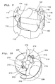
- FIGs 5 and 6 an intermediate position of the assembly of the cutting head 3 in the seat 7 is shown.
- the cutting head 3 has been axially inserted into the seat 7, whereby the fifth concave portion 25 is located exactly opposite the first convex portion 12, and the fourth convex portion is located exactly opposite the second concave portion 14.
- the intermediate position according to Figs 5 and 6 no satisfactory abutment takes place between the portions which are located exactly opposite each other, but there is always a certain clearance between opposite portions which permits turning of the cutting head 3 in relation to the seat 7.
- the centrally located third concave portion 21 of the cutting head 3 will abut against the centrally located first convex portion 12 of the side walls 10, the third convex portion 22 of the cutting head 3 will be located exactly opposite the first concave portion 13 of the side walls 10, the fourth concave portion 23 of the cutting head 3 will be located exactly opposite the second convex portion 15 of the side walls and the fourth convex portion 26 of the cutting head 3 will be located exactly opposite the outer part of the second concave portion 14 of the side walls 10 and the fifth concave portion 25 of the cutting head 3 will be located exactly opposite the central part of the second concave portion 14 of the side walls 10, i.e. a cavity between said portions 25, 14 is formed since both are concave.
- the second support surface 24 of the cutting head 3 When the cutting head 3 is entirely turned inwards to the final position thereof, also the second support surface 24 of the cutting head 3 will abut against the first support surface 16 of the side walls 10. Since the first support surface 16 has an inclination in the axial direction and the second support surface has a corresponding inclination in the assembled position of the cutting head 3, said inclination will prevent movement of the cutting insert in axial direction out of the seat 7 when the support surfaces 16 and 24 are in contact with each other. As is seen in Fig 7 , the contact line between the first support surface 16 and the second support surface 24 is not located on a radius R to the twist drill which passes through the point of intersection of the contact line 16/24 with the circumference for the full diameter of the cutting head 3.
- the contact line 16/24 has such a direction that the distance thereof to the radius R increases in the direction inwards towards the centre of the twist drill, and furthermore, the contact line 16/24 is located on the side of the radius R which goes first in the direction of rotation of the tool, see Fig 7 .
- the side walls 10 "pinches" around the cutting head 3, which in a favourable way promotes a satisfactory clamping of the cutting head 3 between the side walls 10.
- a key is required, which may be formed in several different ways.
- a torque is applied to the cutting head 3, by means of said key which torque gets the protruding transition portion between the third concave portion 21 and the fifth concave portion 25 of the cutting head 3 to pass past the first convex portion 12 of the side walls 10.
- a small outward deflection of the side walls 10 normally takes place, whereby the material of the side walls 10, however, has such an elasticity that they return to the starting position thereof after the cutting head 3 has been assembled in the final position thereof.
- the force-based interaction described above between the support surfaces 16 and 24 also contributes to the sidewalls 10 returning to the starting positions thereof.
- first convex portion 12 of the side walls 10 and the corresponding concave portion of the replaceable cutting head 3 are not located exactly opposite each other when the replaceable cutting head is assembled in the seat 7.
- the first convex portion 12 should exert a pre-stressing force on the replaceable cutting head 3, which ensures that the support surface 24 of the cutting head 3 is pressed against the support surface 16 of the shaft 1.
- the cutting head 3 When the cutting head 3 is consumed, it is disassembled, whereby this takes place by the fact that the cutting head 3 is turned in the opposite direction in comparison with the assembly thereof. Also in this case, a key is used at manual disassembly. A new unconsumed cutting head 3 is then assembled in the way that has been described above.
- a rotatable tool according to the present invention relates to a hollow drill that, among other things, differs principally from a twist drill in that the chips generated at the cutting head 3 are removed through the tubular shaft 101.
- an identical replaceable cutting head 3 is used in the hollow drill according to Figs 8 and 9 as in the twist drill according to Figs 1-7 .
- the seat 107 is formed differently in the hollow drill than in the twist drill.
- the seat 107 of the hollow drill has no bottom surface, but a cylindrical pin 109 constitutes an inferior support for the replaceable cutting head 3 when the same is assembled in the seat 107.
- the two diametrically located sidewalls 110 of the shaft 101 of the hollow drill have a somewhat different design in comparison with the sidewalls 10 of the twist drill.
- the surfaces of the sidewalls 110, turned towards each other, are generally composed of convex and concave portions, whereby said portions have an axial extension which is parallel to the axial direction of the shaft 101.
- the sidewalls 110 have a centrally located first convex portion 112, which is surrounded on both sides by a first and a second concave portion 113 and 114, respectively.
- a first support surface 116 connects a first concave portion 113, whereby the first support surface 116 generally has an extension inwards towards the centre of the tool.
- Said first support surface 116 has the same inclination in the axial direction as the first support surface 16 of the embodiment according to Figs 1-7 , therefore reference is made to the relevant parts of the text which describes the design and function of the first support surface 16.
- the replaceable cutting head 3 is assembled in the seat 107 of the hollow drill in principally the same way as the assembly in the seat 7 of the twist drill, therefore reference is made to the relevant parts of the description above which relate to the assembly of the cutting head 3 in the seat 7. Also the disassembly is carried out in principally the same way as in the embodiment according to Figs 1-7 .
- FIGs 10 and 11 an additional alternative embodiment is shown of a rotatable tool according to the present invention, in the form of a twist drill, where a shaft 201 has two diametrically arranged sidewalls 210, which have an axial extension parallel to the axial direction of the tool.
- the centrally located first convex portion of the sidewalls 210 has in principle been replaced by a tubular pin 212, which is intended to co-operate with a concave portion of the replaceable cutting head 203 when the same is finally assembled in the seat 207 in the embodiment according to Figs 10 and 11 .
- the sidewalls 210 in Figs 10 and 11 have a first and a second concave portion 213 and 214, respectively, on both sides of the first convex portion/tubular pin 212. Since the tubular pin 212 is provided with an axial slot, it is significantly more compliant than the convex portions 12; 112 of the embodiments described above. This has importance at assembly and disassembly of the replaceable cutting head in the seat.
- the side walls 210 also have first support surfaces 216, which in a corresponding way as the support surfaces 16; 116 have an inclination in the axial direction in order to prevent the cutting head 203 unintentionally falling out of the seat 207.
- the cutting head 203 is shown during assembly in the seat 207, whereby the cutting head 203 has a somewhat different design in comparison to the cutting head 3.
- the two engagement surfaces 220 have a centrally located third concave portion 221, which is intended to co-operate with the first convex portion 212 of the side walls 210.
- the engagement surfaces 220 have a third convex portion 222, which is intended to be located exactly opposite the first concave portion 213 of the side walls 210.
- the concave portion 213 will serve as a cooling duct in order to supply cooling liquid to the cutting head 203.
- the engagement surfaces 220 have a second support surface 224, which is intended to co-operate with the first support surface 216 of the side walls 210.
- the second support surface 224 has generally an extension inwards towards the centre of the tool when the cutting head 203 is assembled in the seat 207.
- the engagement surfaces 220 have a fourth convex portion 226, which in the assembled position of the cutting head 203 is intended to be exactly opposite the outermost part of the second concave portion 214.
- tubular pin 212 and the corresponding concave portion of the replaceable cutting head 203 are not located exactly opposite each other when the replaceable cutting head 203 is assembled in the seat 207.
- the tubular pin 212 should exert a pre-stressing force on the replaceable cutting head 203 which entails that the support surface 224 of the cutting head 203 is pressed against the support surface 216 of the shaft 201 according to Fig 10 .
- the cutting edges 19; 219 arranged on the cutting head 3; 203 may either be formed in one piece with the cutting head 3; 203 or constitute separate details which for instance are connected at the tip 3; 203 by soldering.
- the cutting edges 19; 219 are integrated with the cutting head 3; 203, the same is preferably manufactured from cemented carbide, ceramics or another comparatively hard material.
- the cutting head is manufactured from a compound material, i.e. that the surface layer consists of a hard material while the core consists of a softer material.
- the rest of the cutting head may be manufactured from a suitable steel grade.
- the number of cutting edges may vary within the scope of the invention. In the embodiments described above, the number of cutting edges is two (2), however, within the scope of the present invention, primarily more cutting edges are also conceivable.
- the sidewalls 10; 110; 210 have an extension all the way up to the free end of the tool.
- the cutting head has such a design that the same covers the free end of the tool.
- the shaft 1; 101 may be provided with one or more slots, having an axial extension.
- the cooling ducts either mouth in the end surfaces of the sidewalls 10; 110 or are formed as concave portions 213 in the sidewalls 210.
- other designs of the cooling ducts are also feasible within the scope of the inventions, whereby it in that context should be mentioned that it is fully conceivable that the tool lacks cooling ducts for certain applications.
Landscapes
- Engineering & Computer Science (AREA)
- Mechanical Engineering (AREA)
- Drilling Tools (AREA)
- Milling Processes (AREA)
Claims (5)
- Outil rotatif avec une tête de coupe (3 ; 203) remplaçable, située à l'extrémité libre, d'enlèvement des copeaux, de l'outil, dans lequel l'outil comprend également une queue (1 ; 101 ; 201) définissant un axe de rotation longitudinal et ayant un siège (7 ; 107 ; 207), dans lequel la tête de coupe (3 ; 203) est destinée à être logée, la queue (1 ; 101 ; 201) comprenant des organes, à l'aide desquels des copeaux, générés par la tête de coupe, peuvent être évacués, la tête de coupe (3 ; 203) comprenant des organes (19 ; 219) pour l'usinage avec enlèvement de copeaux, de préférence de métaux, le siège (7 ; 107 ; 207) et la tête de coupe (3 ; 203) remplaçable comprenant des parties/surfaces (12-16, 21-26 ;112-116, 21-26 ; 212-216, 221-226), qui s'étendent essentiellement à la fois dans la direction longitudinale de l'outil et transversalement à la direction longitudinale de l'outil, la tête de coupe étant positionnable en un état attaché, en réponse à un déplacement relatif entre la tête de coupe et la queue, dans un sens autour de l'axe longitudinal, et positionnable, hors de l'état attaché, en réponse à un déplacement relatif entre la tête de coupe et la queue, dans un sens opposé autour de l'axe longitudinal, au moins une première surface support (16 ; 116 ; 216) du siège (7 ; 107 ; 207), et au moins une deuxième surface support (24 ; 224) de la tête de coupe (3 ; 203), fournissant à la fois la fixation de la tête de coupe (3 ; 203) dans la direction axiale de l'outil, et le transfert de couple entre la queue (1 ; 101 ; 201) et la tête de coupe (3 ; 203), les surfaces support (16 ; 24 ; 216 ; 224) ayant une inclinaison dans la direction axiale, ladite inclinaison étant définie par l'angle que forment entre elles lesdites surfaces support (16, 24 ; 116, 24 ; 216, 224) et une surface inférieure (9 ; 209) du siège (7 ; 107 ; 207), l'angle étant inférieur à 90°,
caractérisé en ce qu'une ligne de contact (16/24) pour les surfaces support (16, 24 ; 116, 24 ; 216, 224), à la position assemblée de la tête de coupe (3 ; 203), forme un angle (α) avec un rayon (R) de l'outil/tête de coupe (3 ; 203) passant par le point d'intersection de la ligne de contact (16/24) avec la circonférence pour le plein diamètre de la tête de coupe (3 ; 203), en ce que la ligne de contact (16/24) est située sur le côté du rayon (R) passant en premier dans le sens de rotation (W) de l'outil, et en ce que l'extrémité de coupe de la tête de coupe comprend une surface avant, tournée vers l'avant, et la deuxième surface support (16 ; 116 ; 216) s'étend vers la surface avant. - Outil selon la revendication 1, caractérisé en ce que les parties/surfaces coopérant mutuellement ont à la fois des parties convexes (12, 15, 22, 26 ; 112, 22, 26 ; 212, 222, 226) et des parties concaves (13, 14, 21, 23, 25 ; 113, 114, 21, 23, 25 ; 213, 214, 221), qui s'étendent principalement dans la direction axiale de l'outil.
- Outil selon la revendication 1 ou 2, caractérisé en ce que les parties/surfaces coopérant mutuellement comprennent une première surface support (16 ; 116 ; 216), en liaison avec le siège (7 ; 107 ; 207), ainsi qu'une deuxième surface support (24 ; 224) sur la tête de coupe (3 ; 203) remplaçable, et en ce que lesdites surfaces support s'étendent globalement vers l'intérieur, vers le centre de l'outil.
- Outil selon l'une quelconque des revendications 1 à 3, caractérisé en ce que les surfaces coopérant du siège (7 ; 107 ; 207) sont agencées sur des surfaces opposées de deux parois latérales (10 ; 110 ; 210), agencées diamétralement, de la queue (1 ; 101 ; 201).
- Outil selon l'une quelconque des revendications 1 à 4, caractérisé en ce qu'une partie convexe du siège (207) est composé d'une tige (212) tubulaire.
Applications Claiming Priority (2)
| Application Number | Priority Date | Filing Date | Title |
|---|---|---|---|
| SE0101965A SE523205C2 (sv) | 2001-06-06 | 2001-06-06 | Roterbart verktyg med utbytbar skärspets vid verktygets spånavverkande fria ände |
| SE0101965 | 2001-06-06 |
Publications (2)
| Publication Number | Publication Date |
|---|---|
| EP1273373A1 EP1273373A1 (fr) | 2003-01-08 |
| EP1273373B1 true EP1273373B1 (fr) | 2009-10-07 |
Family
ID=20284353
Family Applications (1)
| Application Number | Title | Priority Date | Filing Date |
|---|---|---|---|
| EP02445070A Expired - Lifetime EP1273373B1 (fr) | 2001-06-06 | 2002-05-31 | Outil rotatif avec tête de coupe remplaçable |
Country Status (8)
| Country | Link |
|---|---|
| US (1) | US6840717B2 (fr) |
| EP (1) | EP1273373B1 (fr) |
| JP (1) | JP2004527391A (fr) |
| KR (1) | KR100952097B1 (fr) |
| CN (1) | CN1258425C (fr) |
| DE (1) | DE60233917D1 (fr) |
| SE (1) | SE523205C2 (fr) |
| WO (1) | WO2002098590A1 (fr) |
Families Citing this family (31)
| Publication number | Priority date | Publication date | Assignee | Title |
|---|---|---|---|---|
| DE10207257B4 (de) | 2002-02-21 | 2021-02-18 | Kennametal Inc. | Rundlaufschneidwerkzeug mit auswechselbarem Schneideinsatz |
| IL162147A (en) * | 2004-05-24 | 2008-03-20 | Gil Hecht | Drill with interchangeable head |
| IL164888A (en) * | 2004-10-28 | 2009-07-20 | Iscar Ltd | Cutting tool and cutting head for it |
| EP2871014A3 (fr) * | 2005-10-03 | 2015-08-12 | Mitsubishi Materials Corporation | Outil d'alésage et procédé de forage d'un trou pilote |
| SE530191C2 (sv) * | 2006-10-26 | 2008-03-25 | Seco Tools Ab | Skärdel utförd i hårdmetall med friktionsyta för monteringsnyckel |
| DE102007050471A1 (de) * | 2007-10-23 | 2009-04-30 | MAPAL Fabrik für Präzisionswerkzeuge Dr. Kress KG | Werkzeug zur spanenden Bearbeitung von Werkstücken |
| CN102049535B (zh) * | 2008-04-03 | 2013-07-31 | 钴碳化钨硬质合金公司 | 车床刀具、特别是镗孔刀具 |
| SE532280C2 (sv) * | 2008-04-14 | 2009-12-01 | Seco Tools Ab | Verktyg, verktygskropp och skärhuvud |
| US7625161B1 (en) | 2008-08-08 | 2009-12-01 | Kennametal Inc. | Rotary cutting tool assembly and cutting insert and tool shank therefor |
| CN101502927B (zh) * | 2008-12-31 | 2011-03-23 | 东莞市微创工具科技有限公司 | 一种免磨钻头的制备方法及钻头 |
| DE102009044994A1 (de) | 2009-03-18 | 2010-09-23 | Gühring Ohg | Schneidwerkzeug mit austauschbarem Schneideinsatz |
| SE533851C2 (sv) | 2009-06-23 | 2011-02-08 | Sandvik Intellectual Property | Borrverktyg för spånavskiljande bearbetning samt löstopp och grundkropp härför |
| SE533853C2 (sv) | 2009-06-23 | 2011-02-08 | Sandvik Intellectual Property | Borrverktyg för spånavskiljande bearbetning samt löstopp härför |
| SE533850C2 (sv) * | 2009-06-23 | 2011-02-08 | Sandvik Intellectual Property | Borrverktyg av löstoppstyp |
| DE102009044995B8 (de) | 2009-09-24 | 2021-07-22 | Gühring KG | Schneideinsatzträger, Schneideinsatz und drehangetriebenes Schneidwerkzeug |
| SE534648C2 (sv) | 2010-03-26 | 2011-11-08 | Sandvik Intellectual Property | Roterbart verktyg för spånavskiljande bearbetning samt löstopp och grundkropp härför |
| DE102012212146B4 (de) * | 2012-07-11 | 2024-02-01 | Kennametal Inc. | Kupplungsstelle für ein modulares Rotationswerkzeug sowie Werkzeugkopf und Träger für ein solches modulares Rotationswerkzeug |
| DE102013205889B3 (de) | 2013-04-03 | 2014-05-28 | Kennametal Inc. | Kupplungsteil, insbesondere Schneidkopf für ein Rotationswerkzeug sowie ein derartiges Rotationswerkzeug |
| DE102013220884B4 (de) | 2013-10-15 | 2022-02-17 | Kennametal Inc. | Modulares Trägerwerkzeug sowie Werkzeugkopf |
| KR101509954B1 (ko) * | 2013-10-29 | 2015-04-07 | 한국야금 주식회사 | 절삭 인서트 및 인덱서블 드릴 |
| DE102014206796B4 (de) | 2014-04-08 | 2020-10-15 | Kennametal Inc. | Rotationswerkzeug, insbesondere Bohrer sowie Schneidkopf für ein solches Rotationswerkzeug |
| CN104759664A (zh) * | 2015-04-21 | 2015-07-08 | 成都锋宜精密工具制造有限公司 | 自锁式可换头硬质合金钻头 |
| DE102015211744B4 (de) | 2015-06-24 | 2023-07-20 | Kennametal Inc. | Rotationswerkzeug, insbesondere Bohrer, und Schneidkopf für ein solches Rotationswerkzeug |
| USD798921S1 (en) | 2015-10-07 | 2017-10-03 | Kennametal Inc. | Cutting head for modular drill |
| US10071430B2 (en) | 2015-10-07 | 2018-09-11 | Kennametal Inc. | Cutting head, rotary tool and support for the rotary tool and for the accommodation of the cutting head |
| US9937567B2 (en) | 2015-10-07 | 2018-04-10 | Kennametal Inc. | Modular drill |
| USD798922S1 (en) | 2015-10-07 | 2017-10-03 | Kennametal Inc. | Cutting head for rotary drill |
| DE102017204452B4 (de) * | 2017-03-16 | 2022-02-17 | Kennametal Inc. | Rotationswerkzeug |
| US10799958B2 (en) | 2017-08-21 | 2020-10-13 | Kennametal Inc. | Modular rotary cutting tool |
| US10843221B2 (en) * | 2018-11-06 | 2020-11-24 | The Boeing Company | System and method for a coating device |
| CN112077370A (zh) | 2019-06-13 | 2020-12-15 | 肯纳金属印度有限公司 | 可转位钻头刀片 |
Family Cites Families (16)
| Publication number | Priority date | Publication date | Assignee | Title |
|---|---|---|---|---|
| AT286064B (de) * | 1968-01-04 | 1970-11-25 | Hawera Hartmetall Werkzeugfarb | Spiralbohrer |
| JPH0354444A (ja) * | 1989-07-24 | 1991-03-08 | Seiko Epson Corp | 湿度センサ素子 |
| WO1996027469A1 (fr) * | 1995-03-03 | 1996-09-12 | Komet Präzisionswerkzeuge Robert Breuning Gmbh | Outil de forage |
| SE511429C2 (sv) * | 1996-09-13 | 1999-09-27 | Seco Tools Ab | Verktyg, skärdel, verktygskropp för skärande bearbetning samt metod för montering av skärdel till verktygskropp |
| IL120948A0 (en) * | 1997-05-29 | 1997-09-30 | Iscar Ltd | Cutting tool assembly |
| IL123858A (en) * | 1998-03-27 | 2003-05-29 | Iscar Ltd | Drilling head |
| DE19834635C2 (de) * | 1998-07-31 | 2001-07-26 | Guehring Joerg | Bohrwerkzeug mit einem gegen Lösen gesicherten, austauschbaren Schneideinsatz |
| US6315504B1 (en) | 1998-10-27 | 2001-11-13 | Nachi-Fujikoshi Corporation | Twist Drill |
| JP2000198011A (ja) * | 1998-10-27 | 2000-07-18 | Nachi Fujikoshi Corp | ツイストドリル |
| DE29904056U1 (de) * | 1999-03-05 | 1999-06-02 | Drebo Werkzeugfab Gmbh | Steinbohrer |
| KR100639527B1 (ko) * | 1999-08-03 | 2006-10-30 | 케나메탈 아이엔씨. | 교체 가능한 절단 헤드를 가진 드릴 |
| JP3972549B2 (ja) | 2000-01-20 | 2007-09-05 | 井関農機株式会社 | 洗米炊飯装置 |
| US20060012881A1 (en) * | 2000-05-25 | 2006-01-19 | Atomic Telecom | Atomic layer controlled optical filter design for next generation dense wavelength division multiplexer |
| DE10042990A1 (de) * | 2000-09-01 | 2002-03-28 | Kennametal Inc | Rundlauf-Schneidwerkzeug, z. B. Bohrer |
| US6485235B1 (en) * | 2001-05-08 | 2002-11-26 | Allied Machine & Engineering Corp. | Cutting tool assembly with replaceable cutting head |
| US6506003B1 (en) * | 2001-10-02 | 2003-01-14 | Kennametal Inc. | Cutting tool |
-
2001
- 2001-06-06 SE SE0101965A patent/SE523205C2/sv not_active IP Right Cessation
-
2002
- 2002-05-31 KR KR1020037015824A patent/KR100952097B1/ko not_active IP Right Cessation
- 2002-05-31 WO PCT/SE2002/001043 patent/WO2002098590A1/fr active Application Filing
- 2002-05-31 DE DE60233917T patent/DE60233917D1/de not_active Expired - Lifetime
- 2002-05-31 EP EP02445070A patent/EP1273373B1/fr not_active Expired - Lifetime
- 2002-05-31 CN CNB028112318A patent/CN1258425C/zh not_active Expired - Fee Related
- 2002-05-31 JP JP2003501620A patent/JP2004527391A/ja active Pending
- 2002-06-05 US US10/161,640 patent/US6840717B2/en not_active Expired - Lifetime
Also Published As
| Publication number | Publication date |
|---|---|
| SE0101965D0 (sv) | 2001-06-06 |
| CN1512927A (zh) | 2004-07-14 |
| DE60233917D1 (de) | 2009-11-19 |
| JP2004527391A (ja) | 2004-09-09 |
| US6840717B2 (en) | 2005-01-11 |
| SE0101965L (sv) | 2002-12-07 |
| KR20040012892A (ko) | 2004-02-11 |
| CN1258425C (zh) | 2006-06-07 |
| SE523205C2 (sv) | 2004-04-06 |
| EP1273373A1 (fr) | 2003-01-08 |
| US20030002932A1 (en) | 2003-01-02 |
| WO2002098590A8 (fr) | 2004-04-22 |
| WO2002098590A1 (fr) | 2002-12-12 |
| KR100952097B1 (ko) | 2010-04-13 |
Similar Documents
| Publication | Publication Date | Title |
|---|---|---|
| EP1273373B1 (fr) | Outil rotatif avec tête de coupe remplaçable | |
| KR100522987B1 (ko) | 절삭가공용공구 | |
| EP1328366B1 (fr) | Outil pivotant dont l'extremite libre d'enlevement de copeaux est pourvue d'une partie active remplacable | |
| US7377730B2 (en) | Drill with releasably mounted cutting head | |
| CN1894064B (zh) | 具有螺旋形几何形状的切削嵌入件及钻孔工具组件 | |
| KR100340397B1 (ko) | 칩제거용내부공동을갖는드릴본체 | |
| KR101542279B1 (ko) | 회전 절삭 기계가공용 공구 | |
| US8317439B2 (en) | Cutting tool | |
| KR101573548B1 (ko) | 칩 제거 가공을 위한 드릴 공구 및 루즈 탑과 이를 위한 기본체 | |
| US7972094B2 (en) | Rotary cutting tool having releasably mounted self-clamping cutting head with locking member | |
| EP2524755B2 (fr) | Outil de perçage rotatif ainsi que le corps de base associé | |
| EP0298061B1 (fr) | Foret et élément tranchant approprié | |
| US5860773A (en) | Drilling tool with rounded insert support surfaces | |
| CA3079146A1 (fr) | Tete de coupe et outil de coupe rotatif la comprenant serree de maniere liberable sur une queue par l'intermediaire d'une broche de positionnement | |
| KR20110005238A (ko) | 심혈 절삭용 드릴 헤드 | |
| US20010031177A1 (en) | Interference fit type cutting tool | |
| EP3677367A1 (fr) | Insert de coupe indexable, corps d'outil d'un outil de forage et outil de forage |
Legal Events
| Date | Code | Title | Description |
|---|---|---|---|
| PUAI | Public reference made under article 153(3) epc to a published international application that has entered the european phase |
Free format text: ORIGINAL CODE: 0009012 |
|
| AK | Designated contracting states |
Kind code of ref document: A1 Designated state(s): AT BE CH CY DE DK ES FI FR GB GR IE IT LI LU MC NL PT SE TR |
|
| AX | Request for extension of the european patent |
Free format text: AL;LT;LV;MK;RO;SI |
|
| 17P | Request for examination filed |
Effective date: 20030425 |
|
| AKX | Designation fees paid |
Designated state(s): DE FR GB SE |
|
| RAP1 | Party data changed (applicant data changed or rights of an application transferred) |
Owner name: SANDVIK INTELLECTUAL PROPERTY HB |
|
| RAP1 | Party data changed (applicant data changed or rights of an application transferred) |
Owner name: SANDVIK INTELLECTUAL PROPERTY AB |
|
| 17Q | First examination report despatched |
Effective date: 20070704 |
|
| GRAP | Despatch of communication of intention to grant a patent |
Free format text: ORIGINAL CODE: EPIDOSNIGR1 |
|
| GRAS | Grant fee paid |
Free format text: ORIGINAL CODE: EPIDOSNIGR3 |
|
| GRAA | (expected) grant |
Free format text: ORIGINAL CODE: 0009210 |
|
| AK | Designated contracting states |
Kind code of ref document: B1 Designated state(s): DE FR GB SE |
|
| REG | Reference to a national code |
Ref country code: GB Ref legal event code: FG4D |
|
| REF | Corresponds to: |
Ref document number: 60233917 Country of ref document: DE Date of ref document: 20091119 Kind code of ref document: P |
|
| PG25 | Lapsed in a contracting state [announced via postgrant information from national office to epo] |
Ref country code: SE Free format text: LAPSE BECAUSE OF FAILURE TO SUBMIT A TRANSLATION OF THE DESCRIPTION OR TO PAY THE FEE WITHIN THE PRESCRIBED TIME-LIMIT Effective date: 20091007 |
|
| PLBE | No opposition filed within time limit |
Free format text: ORIGINAL CODE: 0009261 |
|
| STAA | Information on the status of an ep patent application or granted ep patent |
Free format text: STATUS: NO OPPOSITION FILED WITHIN TIME LIMIT |
|
| 26N | No opposition filed |
Effective date: 20100708 |
|
| REG | Reference to a national code |
Ref country code: FR Ref legal event code: PLFP Year of fee payment: 15 |
|
| REG | Reference to a national code |
Ref country code: FR Ref legal event code: PLFP Year of fee payment: 16 |
|
| PGFP | Annual fee paid to national office [announced via postgrant information from national office to epo] |
Ref country code: FR Payment date: 20170413 Year of fee payment: 16 Ref country code: GB Payment date: 20170531 Year of fee payment: 16 |
|
| GBPC | Gb: european patent ceased through non-payment of renewal fee |
Effective date: 20180531 |
|
| PG25 | Lapsed in a contracting state [announced via postgrant information from national office to epo] |
Ref country code: FR Free format text: LAPSE BECAUSE OF NON-PAYMENT OF DUE FEES Effective date: 20180531 Ref country code: GB Free format text: LAPSE BECAUSE OF NON-PAYMENT OF DUE FEES Effective date: 20180531 |
|
| PGFP | Annual fee paid to national office [announced via postgrant information from national office to epo] |
Ref country code: DE Payment date: 20190521 Year of fee payment: 18 |
|
| REG | Reference to a national code |
Ref country code: DE Ref legal event code: R119 Ref document number: 60233917 Country of ref document: DE |
|
| PG25 | Lapsed in a contracting state [announced via postgrant information from national office to epo] |
Ref country code: DE Free format text: LAPSE BECAUSE OF NON-PAYMENT OF DUE FEES Effective date: 20201201 |