EP1273368A2 - Device for the extraction of forged workpieces, extraction unit comprising this device and the machine for the production of forged workpieces - Google Patents
Device for the extraction of forged workpieces, extraction unit comprising this device and the machine for the production of forged workpieces Download PDFInfo
- Publication number
- EP1273368A2 EP1273368A2 EP02013293A EP02013293A EP1273368A2 EP 1273368 A2 EP1273368 A2 EP 1273368A2 EP 02013293 A EP02013293 A EP 02013293A EP 02013293 A EP02013293 A EP 02013293A EP 1273368 A2 EP1273368 A2 EP 1273368A2
- Authority
- EP
- European Patent Office
- Prior art keywords
- extraction
- forged
- fact
- details
- forged details
- Prior art date
- Legal status (The legal status is an assumption and is not a legal conclusion. Google has not performed a legal analysis and makes no representation as to the accuracy of the status listed.)
- Granted
Links
- 238000000605 extraction Methods 0.000 title claims abstract description 95
- 238000004519 manufacturing process Methods 0.000 title claims description 6
- 238000005242 forging Methods 0.000 claims abstract description 12
- 230000033001 locomotion Effects 0.000 claims description 6
- 239000011159 matrix material Substances 0.000 description 4
- 230000008878 coupling Effects 0.000 description 3
- 238000010168 coupling process Methods 0.000 description 3
- 238000005859 coupling reaction Methods 0.000 description 3
- 239000011435 rock Substances 0.000 description 2
- 238000005553 drilling Methods 0.000 description 1
- 238000000034 method Methods 0.000 description 1
Images


Classifications
-
- B—PERFORMING OPERATIONS; TRANSPORTING
- B21—MECHANICAL METAL-WORKING WITHOUT ESSENTIALLY REMOVING MATERIAL; PUNCHING METAL
- B21J—FORGING; HAMMERING; PRESSING METAL; RIVETING; FORGE FURNACES
- B21J13/00—Details of machines for forging, pressing, or hammering
- B21J13/08—Accessories for handling work or tools
- B21J13/14—Ejecting devices
Definitions
- the present invention refers to a device for the extraction of forged details.
- the present invention refers to a device for the extraction of forged details, particularly but not exclusively suitable to be used for the extraction of forged details from the matrix of machines for the production of said details.
- the present invention refers to an extraction unit comprising the device for the extraction of the forged details.
- the present invention refers to a machine for the production of said forged details.
- the aim of the present invention is to provide a device for the extraction of forged details and solve the above-mentioned drawbacks.
- a device for the extraction of forged details a driving device; a command device and an adjusting device of the extraction length wherein said adjusting device connects the extraction length with the one of the product to be extracted.
- the device for the extraction of forged details of the present invention marked as a whole with 1 comprises a base 2 coupled with a forging head 3 which supports an extraction bar 4 of the forged details, a driving device 5, a command device 6 and an adjusting device of the extraction length 7.
- the forging head 3 which is coupled with the base 2, comprises a forging matrix 10 to forge, for example, a rivet 11, a thrust collar 12, a striker 13 and a support 14.
- the forging matrix 10 and the thrust collar 12 are respectively provided with an ejection pin 15 and a thrust pin 16 placed on the same axis which are already known and therefore they are not further described.
- the extraction bar 4 is rod-shaped, preferably cylindrical and it slides inside a drilled screw 20 which is screwed on a support 21 fastened to the base 2 with screws 22 and opposite to the forging head 3.
- the support 21 is fastened to the base 2 in such a way that the axis of the extraction bar 4 corresponds to the one of the thrust pin 16 and of the ejection pin 15.
- the base 2 is provided with a pass-through hole. 23 having a diameter which is higher than the external one of the drilled screw 20 and is coaxial both to the pins of the forging head 3 and to the extraction bar 4 in such a way that the latter is able to freely cross it.
- the extraction bar 4 On the end which is far from the forging head 3, the extraction bar 4 is provided with a double-headed nut 24 which is locked by a lock nut 25 and it is sized in such a way that its thrust end 26 can reach the coupling surface of the forging head 3 to the base 2.
- the extraction bar 4 is finally provided with a collar 27 or thrust collar, which is placed on the thrust end 26 side at a distance from the end of the drilled screw 20 which is equal to the length of the detail to be produced and therefore equal to the extraction length.
- the driving device 5 comprises a first rocker 30 which is rotatingly pivoted on the pivot 31, a tappet 32 and a second rocker 33 which is rotatingly pivoted on the pivot 34.
- the first rocker 30, in the embodiment described in this example, comprises a first lever 35 and a second lever 36 which are integral between them through a safety screw 37 in correspondence with the reciprocally opposite relevant arms.
- the second arm 38 of the first lever 35 has, at its end, a fork 39 which is operatively associated to the double-headed nut 24.
- a first end of the tappet 32 is rotatingly associated to the second arm 40 of the lever 36 through a pivot 41, this tappet 32 is provided with a roller 42 at the opposite end.
- the second rocker 33 has a first arm 43 which is abutted on the roller 42 of the tappet 32 through a cylindrical-shaped surface 44 having an axis parallel to the one of the pivot 34 and facing the tappet 32; while the second arm 45, at its end, is provided with a roller 46.
- the driving device 5 is completed by a first spring device 47 associated to the first rocker 30 and by a second spring device 48 associated to the second rocker 33 which is constantly acting on said driving device 5 in order to return to the rest state or at the beginning of the working cycle.
- the command device 6 comprises a cam 50 which is splined on a shaft 51 which rotates in a suitable seat provided on the base 2.
- the adjusting device of the extraction length 7 comprises a lever 60 which is rotatingly pivoted on the pivot 61 and a connecting rod 62.
- a first arm 63 of the lever 60 has a fork 64 at its end which is operatively associated to the drilled screw 20 which, in its turn, has a proper seat for said fork 64.
- the connecting rod 62 is rotatingly associated, with one of its first ends, to the second arm 65 of the lever 60 through a pivot 66, while the opposite end is rotatingly associated to the tappet 32 through a pivot 67 substantially in the middle of the same tappet 32.
- the adjusting device of the extraction length 7 has one command means.
- the one command means marked with 70 of the adjusting device of the extraction length 7 comprises an engine 71 which is equipped with a splined pinion 72 on its shaft, a drive or chain belt 73, preferably a toothed belt and a toothed wheel 74 which, in rotation, is coupled with the drilled screw 20.
- the coupling between the toothed wheel 74 and the drilled screw 20 is carried out through a key 75, which is fastened to said toothed wheel 74 through a screw 76 which is engaged in a relevant groove 77 placed along a generating line of the external surface of said drilled screw 20; so that during a rotation the toothed wheel 74 and the drilled screw 20 can slide each other.
- the coupling between the toothed wheel 74 and the drilled screw 20 can be carried out by any other form locking suitable for this purpose.
- the only command means 70 is completed by a hydraulic nut 78 to lock the drilled screw 20 which is well known and therefore it is not further described.
- the device for the extraction of forged details of the present invention operates as described here below.
- the shaft 51 of the command device 6 rotates and keeps in rotation the cam 50 which, engaging the roller 46, makes the second rocker 33 rock at each turn.
- the second rocker 33 with its surface 44, pushes the tappet 32 which, in its turn, makes the first rocker 30 rock.
- the first rocker 30 pushes the extraction bar 4 making it slide in the drilled screw 20, through the fork 39 of its arm 38, which is operatively associated to the double-headed nut 24.
- the extraction bar 4, with its end 26, pushes the thrust pin 16 which, in its turn, pushes the ejection pin 15 so that the forged detail 11 is extracted from the matrix 10.
- the cam 50 is at its utmost lift position.
- the device returns to the rest state or at the beginning of the cycle ready for the subsequent one continuing the rotation of the cam 50 and being stressed by the spring devices 47 and 48.
- the adjusting device of the extraction length 7 is unlocked by the unlocking of the hydraulic nut 78 so that the drilled screw 20 and, consequently, also the lever 60 can move.
- the engine 71 through the belt 73 puts into rotation the toothed wheel 75 which, in its turn, makes the drilled screw 20 rotate which, during the rotation, translates along its axis. While translating, the drilled screw 20 drags the fork 64 of the arm 63 of the lever 60 to make it rotate.
- the lever 60 with its arm 65 acts on the connecting rod 62 which, in its turn, acts on the tappet 32. In such a way, the tappet 32 changes the contact point of the roller 42 along the surface 44 of the second rocker 33.
- the layout of the surface 44 is such that when the position of the roller 42 changes, a rotation of the first rocker 30 takes place together with a consequent movement of the extraction bar 4.
- the stroke of the drilled screw 20 has been related to the one of the extraction bar 4; this relation is univocal so that at each movement of the drilled screw 20, a correspondent and predetermined movement of the extraction bar 4 takes place thus obtaining the automatic adjustment both of the detail and of the extraction length acting on one adjusting command means.
- the proportioning of the components not only connect the stroke of the drilled screw 20 with the one of the extraction bar 4, but it must also have the following features.
- the curvature of the surface 44 of the second rocker 33 is such that the utmost reachable position of the extraction bar 4 must be constant when the extraction stroke changes.
- the extraction stroke of the extraction bar 4 which corresponds to the length of the detail 11 to be extracted, is determined by the position of the collar or thrust collar 27 with respect to the end of the drilled screw 20.
- an extraction unit as a whole, comprising the device to extract forged details according to the present invention is marked with 80.
- the extraction unit 80 comprises a plurality of devices for the extraction of forged details 1 placed side by side.
- the individual cams 50 can be replaced by one cam and also the second rocker 33 of each single device can be replaced by one rocker; or in the one extraction device the adjusting command means can be replaced by a manual one.
- Figures 4-6 show a different embodiment of the one command means of the adjusting device of the extraction length 7 which is marked with 90 comprising the engine 71, a universal joint 91 and a drive unit 92 coupled with an elongation 93 of the extraction bar 4.
- the drive unit 92 shown in figure 5, comprises a fixed support 94 which rotatingly houses a sleeve 95 through bearings 96 and 97.
- the sleeve 95 shows an end 98 which is suitable for the connection to the universal joint 91, while the opposite end is equipped with a form locking 99 suitable for the housing of the elongation 93 of the extraction bar 4. Moreover, the sleeve 95 has an axial drilling 100 which can house the elongation 93 of the extraction bar 4. As it is shown in figure 6, the form locking 99 is made by a block 101 fastened by screws 102 to the sleeve 95 in order to have a surface 103 facing the axis of the same sleeve.
- the elongation 93 of the extraction bar 4 shows a surface 104 which is parallel to its axis in such a way to be coupled with the surface 103 of the form locking 99 of the sleeve 95.
- the extraction bar 4 and the drilled screw 20 are integral in rotation through a form locking which is equal to the form locking 99; this form locking is carried out through a surface 105 on the same extraction bar 4 and a block 106 which is fastened through screws 107 to said drilled screw 20.
Landscapes
- Engineering & Computer Science (AREA)
- Mechanical Engineering (AREA)
- Forging (AREA)
- Extraction Or Liquid Replacement (AREA)
- Collation Of Sheets And Webs (AREA)
Abstract
Description
- The present invention refers to a device for the extraction of forged details.
- More particularly, the present invention refers to a device for the extraction of forged details, particularly but not exclusively suitable to be used for the extraction of forged details from the matrix of machines for the production of said details.
- As a second object, the present invention refers to an extraction unit comprising the device for the extraction of the forged details.
- As a further object, the present invention refers to a machine for the production of said forged details.
- It is known that, in a machine for the production of forged details, the length adjustment of the product shank and the adjustment of the extraction stroke of the device extracting the product after the forging are to be provided.
- These adjustments are independently carried out by very expensive chain kinematics motions which require long adjusting times and therefore they are expensive both for intervention and adjusting costs and for the relevant downtime.
- The aim of the present invention is to provide a device for the extraction of forged details and solve the above-mentioned drawbacks.
- According to the present invention, these and other aims will result from the following description and are obtained by a device for the extraction of forged details; a driving device; a command device and an adjusting device of the extraction length wherein said adjusting device connects the extraction length with the one of the product to be extracted.
- Building and functional features of the device for the extraction of forged details of the present invention, will be better understood from the following description wherein reference is made to the figures of the enclosed drawings which represent a preferred and non limitative embodiment wherein:
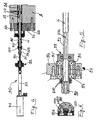
- figure 1 is a section view of the device for the extraction of forged details of the present invention;
- figure 2 is a section view of the command device of the adjusting device of the device for the extraction of forged details of figure 1;
- figure 3 is a section view of an extraction unit comprising the device for the extraction of forged details of figure 1;
- figure 4 is a section view of a different embodiment of the command device of the device for the extraction of forged details of figure 1;
- figure 5 is a section view of a component of the different embodiment of figure 4; and
- figure 6 is a section view according to the line VI-VI of figure 5.
- With reference to figure 1, the device for the extraction of forged details of the present invention marked as a whole with 1, comprises a
base 2 coupled with a forging head 3 which supports anextraction bar 4 of the forged details, a driving device 5, a command device 6 and an adjusting device of the extraction length 7. - The forging head 3 which is coupled with the
base 2, comprises a forgingmatrix 10 to forge, for example, arivet 11, athrust collar 12, astriker 13 and asupport 14. Theforging matrix 10 and thethrust collar 12 are respectively provided with anejection pin 15 and athrust pin 16 placed on the same axis which are already known and therefore they are not further described. - The
extraction bar 4 is rod-shaped, preferably cylindrical and it slides inside a drilledscrew 20 which is screwed on asupport 21 fastened to thebase 2 withscrews 22 and opposite to the forging head 3. - The
support 21 is fastened to thebase 2 in such a way that the axis of theextraction bar 4 corresponds to the one of thethrust pin 16 and of theejection pin 15. - The
base 2 is provided with a pass-through hole. 23 having a diameter which is higher than the external one of the drilledscrew 20 and is coaxial both to the pins of the forging head 3 and to theextraction bar 4 in such a way that the latter is able to freely cross it. - On the end which is far from the forging head 3, the
extraction bar 4 is provided with a double-headed nut 24 which is locked by alock nut 25 and it is sized in such a way that itsthrust end 26 can reach the coupling surface of the forging head 3 to thebase 2. - The
extraction bar 4 is finally provided with acollar 27 or thrust collar, which is placed on thethrust end 26 side at a distance from the end of the drilledscrew 20 which is equal to the length of the detail to be produced and therefore equal to the extraction length. - The driving device 5 comprises a
first rocker 30 which is rotatingly pivoted on thepivot 31, a tappet 32 and asecond rocker 33 which is rotatingly pivoted on thepivot 34. Thefirst rocker 30, in the embodiment described in this example, comprises afirst lever 35 and asecond lever 36 which are integral between them through asafety screw 37 in correspondence with the reciprocally opposite relevant arms. Thesecond arm 38 of thefirst lever 35 has, at its end, afork 39 which is operatively associated to the double-headed nut 24. A first end of thetappet 32 is rotatingly associated to thesecond arm 40 of thelever 36 through apivot 41, thistappet 32 is provided with aroller 42 at the opposite end. Thesecond rocker 33 has afirst arm 43 which is abutted on theroller 42 of thetappet 32 through a cylindrical-shaped surface 44 having an axis parallel to the one of thepivot 34 and facing thetappet 32; while thesecond arm 45, at its end, is provided with aroller 46. The driving device 5 is completed by afirst spring device 47 associated to thefirst rocker 30 and by asecond spring device 48 associated to thesecond rocker 33 which is constantly acting on said driving device 5 in order to return to the rest state or at the beginning of the working cycle. - The command device 6 comprises a
cam 50 which is splined on ashaft 51 which rotates in a suitable seat provided on thebase 2. - The adjusting device of the extraction length 7 comprises a
lever 60 which is rotatingly pivoted on the pivot 61 and a connectingrod 62. In the embodiment described in this example, a first arm 63 of thelever 60 has afork 64 at its end which is operatively associated to the drilledscrew 20 which, in its turn, has a proper seat for saidfork 64. The connectingrod 62 is rotatingly associated, with one of its first ends, to the second arm 65 of thelever 60 through apivot 66, while the opposite end is rotatingly associated to thetappet 32 through apivot 67 substantially in the middle of thesame tappet 32. - The adjusting device of the extraction length 7 has one command means.
- With reference to figure 2, the one command means marked with 70 of the adjusting device of the extraction length 7, comprises an
engine 71 which is equipped with asplined pinion 72 on its shaft, a drive orchain belt 73, preferably a toothed belt and atoothed wheel 74 which, in rotation, is coupled with the drilledscrew 20. In this example the coupling between thetoothed wheel 74 and the drilledscrew 20 is carried out through akey 75, which is fastened to saidtoothed wheel 74 through ascrew 76 which is engaged in arelevant groove 77 placed along a generating line of the external surface of said drilledscrew 20; so that during a rotation thetoothed wheel 74 and the drilledscrew 20 can slide each other. Alternatively, the coupling between thetoothed wheel 74 and the drilledscrew 20 can be carried out by any other form locking suitable for this purpose. The only command means 70 is completed by ahydraulic nut 78 to lock the drilledscrew 20 which is well known and therefore it is not further described. - The device for the extraction of forged details of the present invention operates as described here below.
- During the operating phase, as shown, for example, in figure 1 where the device for the extraction of forged
details 1 is shown during the phase of the end stroke of extraction, the adjusting device of the extraction length 7 is locked by thehydraulic nut 78 in the position which is expected for the current extraction length. In such a way, the drilledscrew 20 is fixed and, consequently, also thelever 60 is kept fixed through thefork 64 of its arm 63. - The
shaft 51 of the command device 6 rotates and keeps in rotation thecam 50 which, engaging theroller 46, makes thesecond rocker 33 rock at each turn. Thesecond rocker 33, with itssurface 44, pushes thetappet 32 which, in its turn, makes thefirst rocker 30 rock. Thefirst rocker 30 pushes theextraction bar 4 making it slide in thedrilled screw 20, through thefork 39 of itsarm 38, which is operatively associated to the double-headed nut 24. Theextraction bar 4, with itsend 26, pushes thethrust pin 16 which, in its turn, pushes theejection pin 15 so that the forgeddetail 11 is extracted from thematrix 10. At this moment, thecam 50 is at its utmost lift position. The device returns to the rest state or at the beginning of the cycle ready for the subsequent one continuing the rotation of thecam 50 and being stressed by thespring devices - During the adjusting phase, the adjusting device of the extraction length 7 is unlocked by the unlocking of the
hydraulic nut 78 so that the drilledscrew 20 and, consequently, also thelever 60 can move. - In this state, the
engine 71 through thebelt 73 puts into rotation thetoothed wheel 75 which, in its turn, makes thedrilled screw 20 rotate which, during the rotation, translates along its axis. While translating, the drilledscrew 20 drags thefork 64 of the arm 63 of thelever 60 to make it rotate. Thelever 60 with its arm 65 acts on the connectingrod 62 which, in its turn, acts on thetappet 32. In such a way, thetappet 32 changes the contact point of theroller 42 along thesurface 44 of thesecond rocker 33. The layout of thesurface 44 is such that when the position of theroller 42 changes, a rotation of thefirst rocker 30 takes place together with a consequent movement of theextraction bar 4. In such a way, the stroke of the drilledscrew 20 has been related to the one of theextraction bar 4; this relation is univocal so that at each movement of the drilledscrew 20, a correspondent and predetermined movement of theextraction bar 4 takes place thus obtaining the automatic adjustment both of the detail and of the extraction length acting on one adjusting command means. - The proportioning of the components, not only connect the stroke of the drilled
screw 20 with the one of theextraction bar 4, but it must also have the following features. - The curvature of the
surface 44 of thesecond rocker 33 is such that the utmost reachable position of theextraction bar 4 must be constant when the extraction stroke changes. - The extraction stroke of the
extraction bar 4, which corresponds to the length of thedetail 11 to be extracted, is determined by the position of the collar orthrust collar 27 with respect to the end of the drilledscrew 20. - With reference to figure 3, an extraction unit, as a whole, comprising the device to extract forged details according to the present invention is marked with 80. The
extraction unit 80 comprises a plurality of devices for the extraction of forgeddetails 1 placed side by side. - In the
extraction unit 80, theindividual cams 50 can be replaced by one cam and also thesecond rocker 33 of each single device can be replaced by one rocker; or in the one extraction device the adjusting command means can be replaced by a manual one. - Figures 4-6 show a different embodiment of the one command means of the adjusting device of the extraction length 7 which is marked with 90 comprising the
engine 71, auniversal joint 91 and adrive unit 92 coupled with anelongation 93 of theextraction bar 4. Thedrive unit 92 shown in figure 5, comprises afixed support 94 which rotatingly houses asleeve 95 throughbearings 96 and 97. - The
sleeve 95 shows anend 98 which is suitable for the connection to theuniversal joint 91, while the opposite end is equipped with aform locking 99 suitable for the housing of theelongation 93 of theextraction bar 4. Moreover, thesleeve 95 has anaxial drilling 100 which can house theelongation 93 of theextraction bar 4. As it is shown in figure 6, the form locking 99 is made by ablock 101 fastened byscrews 102 to thesleeve 95 in order to have asurface 103 facing the axis of the same sleeve. - The
elongation 93 of theextraction bar 4 shows asurface 104 which is parallel to its axis in such a way to be coupled with thesurface 103 of the form locking 99 of thesleeve 95. - The
extraction bar 4 and the drilledscrew 20 are integral in rotation through a form locking which is equal to the form locking 99; this form locking is carried out through asurface 105 on thesame extraction bar 4 and ablock 106 which is fastened through screws 107 to said drilledscrew 20. - The adjustment of the adjustment device of the length 7 takes place with the same procedure previously described.
- From the previous description it is clear that the device for the extraction of forged details of the present invention allows an optimum adjustment of the extraction length, together with a great building and operating simplicity, thus solving the drawbacks mentioned in the known art.
- Obviously, a technician skilled in the art, can introduce changes and variations or combinations of variations to the above described extraction device to extract the forged details. All these changes, variations or combinations of variations are contained in the field of the present invention as stated by the following claims.
Claims (14)
- A device for the extraction of forged details (1) comprising a base (2), coupled with a forging head (3), supporting an extraction bar (4) to extract the forged details (11), a driving device (5), a command device (6) and an adjusting device of the extraction length (7), characterised by the fact that said adjusting device (7) connects the extraction length with the one of the product to be extracted.
- A device for the extraction of forged details (1) according to claim 1, characterised by the fact that the stroke of the drilled screw (20) and the one of the extraction bar (4) are in univocal relation so that each movement of the drilled screw (20) corresponds to a predetermined movement of the extraction bar (4).
- A device for the extraction of forged details (1) according to the claim 1 or 2 characterised by the fact that the curvature of the surface (44) of the second rocker (33) is such that the utmost position the extraction bar (4) can reach is constant when the extraction stroke changes.
- A device for the extraction of forged details (1) according to each of the previous claims, characterised by the fact that the extraction stroke of the extraction bar (4), corresponding to the length of the detail (11) to be extracted, is determined by the position of the collar (27) with respect to the end of the drilled screw (20).
- A device for the extraction of forged details (1) according to any of the previous claims, characterised by the fact that the extraction bar (4) is cylindrical and rod-shaped and it slides inside a drilled screw (20), its axis coincides with the one of the forging head (3) and it is provided with a double-headed nut (24) which is locked by a lock nut (25) and it is provided with a thrust collar (27).
- A device for the extraction of forged details (1) according to any of the previous claims, characterised by the fact that the driving device (5) comprises a first rocker (30) which is operatively associated to the double-headed nut (24), a tappet (32) which is rotatingly associated to the first rocker (30) and abutted on the surface (44) of a second rocker (33) and a second rocker (33) having a cylindrical surface (44) with an axis parallel to the one of the pivot (34) and a second arm (45) provided with a roller (46) at its end.
- A device for the extraction of forged details (1) according to any of the previous claims, characterised by the fact that it comprises a first spring device (47) associated to the first rocker (30) and a second spring device (48) associated to the second rocker (33) to return at the beginning of the cycle.
- A device for the extraction of forged details (1) according to any of the previous claims, characterised by the fact that the command device (6) comprises a cam (50) which is splined on a shaft (51) which rotates in a seat provided on the base (2).
- A device for the extraction of forged details (1) according to any of the previous claims, characterised by the fact that the adjusting device of the extraction length (7) comprises a lever (60) which is operatively associated to the drilled screw (20) and a connecting bar (62) which is rotatingly associated to the lever (60) and to the tappet (32) in the middle of said tappet (32).
- A device for the extraction of forged details (1) according to any of the above mentioned claims, characterised by the fact that it comprises only one command means (70) of the adjusting device of the extraction length (7) comprising an engine (71) equipped with a pinion (72), a belt (73), a toothed wheel (74) which is coupled in rotation with the drilled screw (20) and a hydraulic nut (78) for the locking of the drilled screw (20).
- A device for the extraction of forged details (1) according to any of the claims from 1 to 9 characterised by the fact of comprising only one command means (90) of the adjusting device of the extraction length (7), comprising an engine (71), a universal joint (91) and a drive unit (92) coupled with an elongation (93) of said extraction bar (4).
- An extraction unit (80) comprising a device for the extraction of forged details (1) according to any of the claims from 1 to 11.
- A machine for the production of forged details comprising an extraction unit (80) referred in claim 12.
- A machine for the production of forged details comprising a device for the extraction of forged details (1) according to one of the previous claims from 1 to 11.
Applications Claiming Priority (2)
| Application Number | Priority Date | Filing Date | Title |
|---|---|---|---|
| ITMI20011403 | 2001-07-02 | ||
| IT2001MI001403A ITMI20011403A1 (en) | 2001-07-02 | 2001-07-02 | DEVICE FOR THE EXTRACTION OF PRINTED DETAILS EXTRACTION GROUP INCLUDING SUCH DEVICE AND MACHINE FOR THE PRODUCTION OF PARTICO |
Publications (3)
| Publication Number | Publication Date |
|---|---|
| EP1273368A2 true EP1273368A2 (en) | 2003-01-08 |
| EP1273368A3 EP1273368A3 (en) | 2003-02-19 |
| EP1273368B1 EP1273368B1 (en) | 2008-03-19 |
Family
ID=11447985
Family Applications (1)
| Application Number | Title | Priority Date | Filing Date |
|---|---|---|---|
| EP02013293A Expired - Lifetime EP1273368B1 (en) | 2001-07-02 | 2002-06-18 | Device for the extraction of forged workpieces, extraction unit comprising this device and the machine for the production of forged workpieces |
Country Status (6)
| Country | Link |
|---|---|
| US (1) | US6804982B2 (en) |
| EP (1) | EP1273368B1 (en) |
| AT (1) | ATE389480T1 (en) |
| DE (1) | DE60225630T2 (en) |
| ES (1) | ES2303539T3 (en) |
| IT (1) | ITMI20011403A1 (en) |
Cited By (1)
| Publication number | Priority date | Publication date | Assignee | Title |
|---|---|---|---|---|
| US6804982B2 (en) | 2001-07-02 | 2004-10-19 | Carlo Salvi & C. S.R.L. | Device for the extraction of forged details, extraction unit comprising this device and the machine for the production of forged details |
Families Citing this family (4)
| Publication number | Priority date | Publication date | Assignee | Title |
|---|---|---|---|---|
| FR2832201B1 (en) | 2001-11-13 | 2004-03-19 | Skf Ab | INSTRUMENT TENSIONING DEVICE AND ASSOCIATED CONTROL METHOD |
| FR2860847B1 (en) | 2003-10-14 | 2006-03-31 | Skf Ab | CLUTCH STOPPING DEVICE |
| CN102225452B (en) * | 2011-03-30 | 2014-11-19 | 扬州锻压机床股份有限公司 | Hydraulic-pneumatic jacking device |
| IT201700058071A1 (en) * | 2017-05-29 | 2018-11-29 | Skf Ab | HUB-WHEEL BEARING GROUP |
Citations (4)
| Publication number | Priority date | Publication date | Assignee | Title |
|---|---|---|---|---|
| GB674173A (en) * | 1949-03-19 | 1952-06-18 | Gkn Group Services Ltd | Improvements in ejector mechanism for heading and like machines |
| US4161113A (en) * | 1978-04-11 | 1979-07-17 | The National Machinery Company | Knockout adjustment mechanism for forging machines |
| US4488426A (en) * | 1980-08-14 | 1984-12-18 | The National Machinery Company | Forging machine for producing rivets or the like having running adjustments |
| EP0950447A2 (en) * | 1998-04-17 | 1999-10-20 | Carlo Salvi & C. S.r.l. | Adjustment device for a forging press |
Family Cites Families (3)
| Publication number | Priority date | Publication date | Assignee | Title |
|---|---|---|---|---|
| US3266071A (en) * | 1965-03-29 | 1966-08-16 | Hilgeland Fa Geb | Cam-controlled apparatus for throwing out the bolts from the counter punch of bolt presses or the like |
| US4538437A (en) * | 1984-06-25 | 1985-09-03 | The National Machinery Company | Forging machine kickout drive with running adjustment |
| ITMI20011403A1 (en) | 2001-07-02 | 2003-01-02 | Carlo Salvi & C S R L | DEVICE FOR THE EXTRACTION OF PRINTED DETAILS EXTRACTION GROUP INCLUDING SUCH DEVICE AND MACHINE FOR THE PRODUCTION OF PARTICO |
-
2001
- 2001-07-02 IT IT2001MI001403A patent/ITMI20011403A1/en unknown
-
2002
- 2002-06-18 ES ES02013293T patent/ES2303539T3/en not_active Expired - Lifetime
- 2002-06-18 AT AT02013293T patent/ATE389480T1/en not_active IP Right Cessation
- 2002-06-18 EP EP02013293A patent/EP1273368B1/en not_active Expired - Lifetime
- 2002-06-18 DE DE60225630T patent/DE60225630T2/en not_active Expired - Lifetime
- 2002-07-01 US US10/187,520 patent/US6804982B2/en not_active Expired - Lifetime
Patent Citations (4)
| Publication number | Priority date | Publication date | Assignee | Title |
|---|---|---|---|---|
| GB674173A (en) * | 1949-03-19 | 1952-06-18 | Gkn Group Services Ltd | Improvements in ejector mechanism for heading and like machines |
| US4161113A (en) * | 1978-04-11 | 1979-07-17 | The National Machinery Company | Knockout adjustment mechanism for forging machines |
| US4488426A (en) * | 1980-08-14 | 1984-12-18 | The National Machinery Company | Forging machine for producing rivets or the like having running adjustments |
| EP0950447A2 (en) * | 1998-04-17 | 1999-10-20 | Carlo Salvi & C. S.r.l. | Adjustment device for a forging press |
Cited By (1)
| Publication number | Priority date | Publication date | Assignee | Title |
|---|---|---|---|---|
| US6804982B2 (en) | 2001-07-02 | 2004-10-19 | Carlo Salvi & C. S.R.L. | Device for the extraction of forged details, extraction unit comprising this device and the machine for the production of forged details |
Also Published As
| Publication number | Publication date |
|---|---|
| DE60225630D1 (en) | 2008-04-30 |
| DE60225630T2 (en) | 2009-03-05 |
| ITMI20011403A0 (en) | 2001-07-02 |
| US6804982B2 (en) | 2004-10-19 |
| ATE389480T1 (en) | 2008-04-15 |
| US20030000276A1 (en) | 2003-01-02 |
| EP1273368B1 (en) | 2008-03-19 |
| EP1273368A3 (en) | 2003-02-19 |
| ES2303539T3 (en) | 2008-08-16 |
| ITMI20011403A1 (en) | 2003-01-02 |
Similar Documents
| Publication | Publication Date | Title |
|---|---|---|
| EP1273368B1 (en) | Device for the extraction of forged workpieces, extraction unit comprising this device and the machine for the production of forged workpieces | |
| EP0726111B1 (en) | Multiple die station forging machine | |
| US4748883A (en) | Apparatus for setting the working stroke of a punching machine | |
| US6647869B2 (en) | Positive lock for infinite adjustable stroke mechanism | |
| CA2616876A1 (en) | A device and a method for holding together tool parts during a hydroforming process | |
| US4395899A (en) | Forging machine for producing rivets or the like having running adjustments | |
| CN107030315B (en) | A kind of boring grab | |
| JPS6134897B2 (en) | ||
| US330901A (en) | Machine for forging bolt-blanks | |
| JP2821474B2 (en) | Press forming machine | |
| JP4605523B2 (en) | Transfer chuck in forging machine | |
| KR100629211B1 (en) | ratating equipment for transfer unit of former | |
| US168135A (en) | Improvement in machines for forging wrench-bar heads | |
| JP2550237Y2 (en) | Chuck device for material transfer of pressure forming machine | |
| JPH0639234U (en) | Forging machine | |
| EP0950447A2 (en) | Adjustment device for a forging press | |
| KR200200906Y1 (en) | A crank shaft of power press | |
| DE3623648A1 (en) | Hammer drill with percussive mechanism | |
| US2362264A (en) | Groove drilling machine | |
| SU1263420A1 (en) | Forging manipulator | |
| US310646A (en) | And oebin claek | |
| US146374A (en) | Improvement in bolt-heading machines | |
| EP0950449A2 (en) | Ejecting device for metallic workpieces | |
| SU1446263A1 (en) | Well-sinking arrangement | |
| KR950007767B1 (en) | Device for material chuck of parts former |
Legal Events
| Date | Code | Title | Description |
|---|---|---|---|
| PUAI | Public reference made under article 153(3) epc to a published international application that has entered the european phase |
Free format text: ORIGINAL CODE: 0009012 |
|
| PUAL | Search report despatched |
Free format text: ORIGINAL CODE: 0009013 |
|
| AK | Designated contracting states |
Kind code of ref document: A2 Designated state(s): AT BE CH CY DE DK ES FI FR GB GR IE IT LI LU MC NL PT SE TR |
|
| AX | Request for extension of the european patent |
Free format text: AL;LT;LV;MK;RO;SI |
|
| AK | Designated contracting states |
Designated state(s): AT BE CH CY DE DK ES FI FR GB GR IE IT LI LU MC NL PT SE TR |
|
| AX | Request for extension of the european patent |
Extension state: AL LT LV MK RO SI |
|
| 17P | Request for examination filed |
Effective date: 20030526 |
|
| AKX | Designation fees paid |
Designated state(s): AT BE CH CY DE DK ES FI FR GB GR IE IT LI LU MC NL PT SE TR |
|
| 17Q | First examination report despatched |
Effective date: 20060626 |
|
| RAP1 | Party data changed (applicant data changed or rights of an application transferred) |
Owner name: CARLO SALVI S.P.A. |
|
| GRAP | Despatch of communication of intention to grant a patent |
Free format text: ORIGINAL CODE: EPIDOSNIGR1 |
|
| GRAS | Grant fee paid |
Free format text: ORIGINAL CODE: EPIDOSNIGR3 |
|
| GRAA | (expected) grant |
Free format text: ORIGINAL CODE: 0009210 |
|
| AK | Designated contracting states |
Kind code of ref document: B1 Designated state(s): AT BE CH CY DE DK ES FI FR GB GR IE IT LI LU MC NL PT SE TR |
|
| REG | Reference to a national code |
Ref country code: GB Ref legal event code: FG4D |
|
| REG | Reference to a national code |
Ref country code: CH Ref legal event code: EP |
|
| REF | Corresponds to: |
Ref document number: 60225630 Country of ref document: DE Date of ref document: 20080430 Kind code of ref document: P |
|
| REG | Reference to a national code |
Ref country code: IE Ref legal event code: FG4D |
|
| REG | Reference to a national code |
Ref country code: CH Ref legal event code: NV Representative=s name: ISLER & ISLER |
|
| PG25 | Lapsed in a contracting state [announced via postgrant information from national office to epo] |
Ref country code: FI Free format text: LAPSE BECAUSE OF FAILURE TO SUBMIT A TRANSLATION OF THE DESCRIPTION OR TO PAY THE FEE WITHIN THE PRESCRIBED TIME-LIMIT Effective date: 20080319 |
|
| REG | Reference to a national code |
Ref country code: ES Ref legal event code: FG2A Ref document number: 2303539 Country of ref document: ES Kind code of ref document: T3 |
|
| PG25 | Lapsed in a contracting state [announced via postgrant information from national office to epo] |
Ref country code: AT Free format text: LAPSE BECAUSE OF FAILURE TO SUBMIT A TRANSLATION OF THE DESCRIPTION OR TO PAY THE FEE WITHIN THE PRESCRIBED TIME-LIMIT Effective date: 20080319 |
|
| NLV1 | Nl: lapsed or annulled due to failure to fulfill the requirements of art. 29p and 29m of the patents act | ||
| PG25 | Lapsed in a contracting state [announced via postgrant information from national office to epo] |
Ref country code: SE Free format text: LAPSE BECAUSE OF FAILURE TO SUBMIT A TRANSLATION OF THE DESCRIPTION OR TO PAY THE FEE WITHIN THE PRESCRIBED TIME-LIMIT Effective date: 20080619 Ref country code: PT Free format text: LAPSE BECAUSE OF FAILURE TO SUBMIT A TRANSLATION OF THE DESCRIPTION OR TO PAY THE FEE WITHIN THE PRESCRIBED TIME-LIMIT Effective date: 20080826 |
|
| PG25 | Lapsed in a contracting state [announced via postgrant information from national office to epo] |
Ref country code: NL Free format text: LAPSE BECAUSE OF FAILURE TO SUBMIT A TRANSLATION OF THE DESCRIPTION OR TO PAY THE FEE WITHIN THE PRESCRIBED TIME-LIMIT Effective date: 20080319 |
|
| EN | Fr: translation not filed | ||
| PLBE | No opposition filed within time limit |
Free format text: ORIGINAL CODE: 0009261 |
|
| STAA | Information on the status of an ep patent application or granted ep patent |
Free format text: STATUS: NO OPPOSITION FILED WITHIN TIME LIMIT |
|
| PG25 | Lapsed in a contracting state [announced via postgrant information from national office to epo] |
Ref country code: MC Free format text: LAPSE BECAUSE OF NON-PAYMENT OF DUE FEES Effective date: 20080630 Ref country code: DK Free format text: LAPSE BECAUSE OF FAILURE TO SUBMIT A TRANSLATION OF THE DESCRIPTION OR TO PAY THE FEE WITHIN THE PRESCRIBED TIME-LIMIT Effective date: 20080319 |
|
| 26N | No opposition filed |
Effective date: 20081222 |
|
| GBPC | Gb: european patent ceased through non-payment of renewal fee |
Effective date: 20080619 |
|
| PG25 | Lapsed in a contracting state [announced via postgrant information from national office to epo] |
Ref country code: IE Free format text: LAPSE BECAUSE OF NON-PAYMENT OF DUE FEES Effective date: 20080618 |
|
| PG25 | Lapsed in a contracting state [announced via postgrant information from national office to epo] |
Ref country code: GB Free format text: LAPSE BECAUSE OF NON-PAYMENT OF DUE FEES Effective date: 20080619 |
|
| PG25 | Lapsed in a contracting state [announced via postgrant information from national office to epo] |
Ref country code: CY Free format text: LAPSE BECAUSE OF FAILURE TO SUBMIT A TRANSLATION OF THE DESCRIPTION OR TO PAY THE FEE WITHIN THE PRESCRIBED TIME-LIMIT Effective date: 20080319 |
|
| PG25 | Lapsed in a contracting state [announced via postgrant information from national office to epo] |
Ref country code: LU Free format text: LAPSE BECAUSE OF NON-PAYMENT OF DUE FEES Effective date: 20080618 |
|
| PG25 | Lapsed in a contracting state [announced via postgrant information from national office to epo] |
Ref country code: TR Free format text: LAPSE BECAUSE OF FAILURE TO SUBMIT A TRANSLATION OF THE DESCRIPTION OR TO PAY THE FEE WITHIN THE PRESCRIBED TIME-LIMIT Effective date: 20080319 |
|
| PG25 | Lapsed in a contracting state [announced via postgrant information from national office to epo] |
Ref country code: GR Free format text: LAPSE BECAUSE OF FAILURE TO SUBMIT A TRANSLATION OF THE DESCRIPTION OR TO PAY THE FEE WITHIN THE PRESCRIBED TIME-LIMIT Effective date: 20080620 |
|
| PG25 | Lapsed in a contracting state [announced via postgrant information from national office to epo] |
Ref country code: FR Free format text: LAPSE BECAUSE OF FAILURE TO SUBMIT A TRANSLATION OF THE DESCRIPTION OR TO PAY THE FEE WITHIN THE PRESCRIBED TIME-LIMIT Effective date: 20090109 |
|
| PGFP | Annual fee paid to national office [announced via postgrant information from national office to epo] |
Ref country code: IT Payment date: 20210630 Year of fee payment: 20 |
|
| PGFP | Annual fee paid to national office [announced via postgrant information from national office to epo] |
Ref country code: BE Payment date: 20210624 Year of fee payment: 20 |
|
| PGFP | Annual fee paid to national office [announced via postgrant information from national office to epo] |
Ref country code: CH Payment date: 20210927 Year of fee payment: 20 |
|
| PGFP | Annual fee paid to national office [announced via postgrant information from national office to epo] |
Ref country code: ES Payment date: 20210924 Year of fee payment: 20 |
|
| PGFP | Annual fee paid to national office [announced via postgrant information from national office to epo] |
Ref country code: DE Payment date: 20210901 Year of fee payment: 20 |
|
| REG | Reference to a national code |
Ref country code: DE Ref legal event code: R071 Ref document number: 60225630 Country of ref document: DE |
|
| REG | Reference to a national code |
Ref country code: ES Ref legal event code: FD2A Effective date: 20220629 |
|
| REG | Reference to a national code |
Ref country code: CH Ref legal event code: PL |
|
| REG | Reference to a national code |
Ref country code: BE Ref legal event code: MK Effective date: 20220618 |
|
| PG25 | Lapsed in a contracting state [announced via postgrant information from national office to epo] |
Ref country code: ES Free format text: LAPSE BECAUSE OF EXPIRATION OF PROTECTION Effective date: 20220619 |