EP1271029A1 - Systeme pour commande pneumatique - Google Patents
Systeme pour commande pneumatique Download PDFInfo
- Publication number
- EP1271029A1 EP1271029A1 EP02011900A EP02011900A EP1271029A1 EP 1271029 A1 EP1271029 A1 EP 1271029A1 EP 02011900 A EP02011900 A EP 02011900A EP 02011900 A EP02011900 A EP 02011900A EP 1271029 A1 EP1271029 A1 EP 1271029A1
- Authority
- EP
- European Patent Office
- Prior art keywords
- piston
- control
- control piston
- plastic
- butt plate
- Prior art date
- Legal status (The legal status is an assumption and is not a legal conclusion. Google has not performed a legal analysis and makes no representation as to the accuracy of the status listed.)
- Granted
Links
Images


Classifications
-
- F—MECHANICAL ENGINEERING; LIGHTING; HEATING; WEAPONS; BLASTING
- F16—ENGINEERING ELEMENTS AND UNITS; GENERAL MEASURES FOR PRODUCING AND MAINTAINING EFFECTIVE FUNCTIONING OF MACHINES OR INSTALLATIONS; THERMAL INSULATION IN GENERAL
- F16K—VALVES; TAPS; COCKS; ACTUATING-FLOATS; DEVICES FOR VENTING OR AERATING
- F16K31/00—Actuating devices; Operating means; Releasing devices
- F16K31/12—Actuating devices; Operating means; Releasing devices actuated by fluid
- F16K31/122—Actuating devices; Operating means; Releasing devices actuated by fluid the fluid acting on a piston
-
- F—MECHANICAL ENGINEERING; LIGHTING; HEATING; WEAPONS; BLASTING
- F15—FLUID-PRESSURE ACTUATORS; HYDRAULICS OR PNEUMATICS IN GENERAL
- F15B—SYSTEMS ACTING BY MEANS OF FLUIDS IN GENERAL; FLUID-PRESSURE ACTUATORS, e.g. SERVOMOTORS; DETAILS OF FLUID-PRESSURE SYSTEMS, NOT OTHERWISE PROVIDED FOR
- F15B13/00—Details of servomotor systems ; Valves for servomotor systems
- F15B13/02—Fluid distribution or supply devices characterised by their adaptation to the control of servomotors
- F15B13/04—Fluid distribution or supply devices characterised by their adaptation to the control of servomotors for use with a single servomotor
- F15B13/042—Fluid distribution or supply devices characterised by their adaptation to the control of servomotors for use with a single servomotor operated by fluid pressure
- F15B13/0426—Fluid distribution or supply devices characterised by their adaptation to the control of servomotors for use with a single servomotor operated by fluid pressure with fluid-operated pilot valves, i.e. multiple stage valves
-
- B—PERFORMING OPERATIONS; TRANSPORTING
- B29—WORKING OF PLASTICS; WORKING OF SUBSTANCES IN A PLASTIC STATE IN GENERAL
- B29C—SHAPING OR JOINING OF PLASTICS; SHAPING OF MATERIAL IN A PLASTIC STATE, NOT OTHERWISE PROVIDED FOR; AFTER-TREATMENT OF THE SHAPED PRODUCTS, e.g. REPAIRING
- B29C33/00—Moulds or cores; Details thereof or accessories therefor
- B29C33/20—Opening, closing or clamping
- B29C33/26—Opening, closing or clamping by pivotal movement
-
- B—PERFORMING OPERATIONS; TRANSPORTING
- B29—WORKING OF PLASTICS; WORKING OF SUBSTANCES IN A PLASTIC STATE IN GENERAL
- B29C—SHAPING OR JOINING OF PLASTICS; SHAPING OF MATERIAL IN A PLASTIC STATE, NOT OTHERWISE PROVIDED FOR; AFTER-TREATMENT OF THE SHAPED PRODUCTS, e.g. REPAIRING
- B29C49/00—Blow-moulding, i.e. blowing a preform or parison to a desired shape within a mould; Apparatus therefor
- B29C49/42—Component parts, details or accessories; Auxiliary operations
- B29C49/4205—Handling means, e.g. transfer, loading or discharging means
- B29C49/42073—Grippers
- B29C49/42085—Grippers holding inside the neck
-
- B—PERFORMING OPERATIONS; TRANSPORTING
- B29—WORKING OF PLASTICS; WORKING OF SUBSTANCES IN A PLASTIC STATE IN GENERAL
- B29C—SHAPING OR JOINING OF PLASTICS; SHAPING OF MATERIAL IN A PLASTIC STATE, NOT OTHERWISE PROVIDED FOR; AFTER-TREATMENT OF THE SHAPED PRODUCTS, e.g. REPAIRING
- B29C49/00—Blow-moulding, i.e. blowing a preform or parison to a desired shape within a mould; Apparatus therefor
- B29C49/42—Component parts, details or accessories; Auxiliary operations
- B29C49/4289—Valve constructions or configurations, e.g. arranged to reduce blowing fluid consumption
Definitions
- the invention relates to a device for pneumatic Control, which led one in a cylinder Control piston, which is in the direction of a Piston longitudinal axis is slidably mounted and in the through the cylinder one from the control piston lockable main flow path runs as well as at the the control piston is provided with a control surface, the a control chamber of the cylinder and facing the Transmission of a control force on the control piston is trained.
- Such devices are particularly in the Production of blow molded containers used to make a coordinated with the execution of the blowing process Feed one or more blowing pressures can.
- the Preforms as well as the blown containers with the help transported different handling equipment become. Has proven particularly the use of Transport mandrels on which the preforms are attached become.
- the preforms can also be used with others Carrying facilities are handled.
- the usage of Tongs for handling preforms and the Use of expanding mandrels for mounting in a Mouth region of the preform are insertable belong also to the available constructions.
- blowing stations used different embodiments known. at Blowing stations on rotating transport wheels arranged, is a book - like Aufklappbarkeit the Mold carrier frequently encountered. But it is also possible relative to each other displaceable or otherwise guided Insert mold carrier. For fixed blowing stations, the are particularly suitable for multiple cavities for Container molding typically becomes parallel mutually arranged plates used as a mold carrier.
- the used for the blowing air supply blowing station Devices for pneumatic control are typically realized as high pressure valves in which a control piston of a control pressure positioned so is that the control piston either a flow path for closes or releases the blowing pressure.
- a control piston of a control pressure positioned so is that the control piston either a flow path for closes or releases the blowing pressure.
- a disadvantage of the known control piston is in particular, that due to the metallic formation of the Control piston an immediate contact with the wall of the surrounding cylinder must be avoided, otherwise a heavy wear would occur.
- To avoid this Kunststoffes are similar to the arrangement of piston rings Guide bands made of plastic or similar soft Used materials that used as guide elements become.
- Guide bands made of plastic or similar soft Used materials that used as guide elements become.
- For these guide bands must be appropriate Recesses introduced in the region of the piston wall which result in corresponding manufacturing costs.
- the assembly of the guide bands also leads to a corresponding cost.
- the object of the present invention is to provide a Device of the type mentioned in the introduction to such construct that the structural design is improved.
- Control piston at least partially made of a plastic is trained.
- control piston made of plastic Due to the design of the control piston made of plastic at least in the plastic-made areas metallic contact with the wall of the cylinder avoided. Separate guide belts can therefore be avoided become.
- the formation of the control piston made of plastic moreover leads to a reduced weight and thus also to a reduced inertia and to a reduced friction in a positioning of the Piston. There are therefore lower positioning forces than in a metallic realization of the control piston required.
- control piston is formed at least in two parts.
- a simple assembly of the individual components of the Control piston can be achieved in that the Butt plate over a snap connection in the area of a Piston shaft of the control piston is attached.
- a positive attachment of the butt plate will also supported by the fact that the butt plate with a web in the groove engages.
- the butt plate with be provided a groove into which a corresponding web intervenes.
- the butt plate at least partially is made of plastic.
- the butt plate at least partially formed of PETP.
- control surface larger as the cross-sectional area of the piston skirt dimensioned is.
- control piston partially made of metal are formed.
- control piston at least partially formed of PETP.
- actuating forces during Closing the valve and holding the valve in the closed position can be specified by that the control piston has a piston skirt whose Cross-sectional area substantially equal to one Cross-sectional area of a closable by the control piston and facing a cylinder interior Flow area of the main flow path dimensioned is.
- Butt plate with a bias from the control piston is held.
- a use of the device for pneumatic control For example, to control the Blas Kunststoffzu arrangement at a device for blow molding.
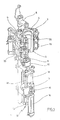
- a device for the transformation of Preforms (1) in container (2) is shown in FIG. 1 and in FIG. 2 shown.
- the device for forming the container (2) consists in Substantially from a blowing station (3), which with a Blow mold (4) into which a preform (1) can be used.
- the preform (1) can be injection-molded part of polyethylene terephthalate be. to Enabling insertion of the preform (1) in the Blow mold (4) and to enable removal of the finished container (2) consists of the blow mold (4) Mold halves (5, 6) and a bottom part (7) of a Lifting device (8) is positionable.
- the preform (1) can in the area of blow station (3) from a transport mandrel (9), which together with the preform (1) a plurality of treatment stations within the Device undergoes. But it is also possible, the Preform (1) for example via pliers or others Use handling agent directly in the blow mold (4).
- a connecting piston (10) arranged which supplies compressed air to the preform (1) and at the same time a seal relative to the transport mandrel (9) makes.
- a connecting piston (10) arranged which supplies compressed air to the preform (1) and at the same time a seal relative to the transport mandrel (9) makes.
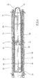
- a stretching of the preform (1) takes place with the aid of a Stretching bar (11), positioned by a cylinder (12) becomes.
- a mechanical positioning of the stretch rod (11) over Curve segments to perform by Abgriffrollen are charged.
- the use of curve segments is especially useful when a plurality of Blowing stations (3) arranged on a rotating blowing wheel are.
- a use of cylinders (12) is appropriate if stationarily arranged blowing stations (3) provided are.
- Fig. 1 is the Stretching system designed such that a tandem arrangement of two cylinders (12) is provided. Of a Primary cylinder (13), the stretch rod (11) before Beginning of the actual stretching process up to the area a bottom (14) of the preform (1) driven. While the actual stretching process, the primary cylinder (13) with extended stretch rod together with a Primary cylinder (13) carrying carriage (15) of a Secondary cylinder (16) or via a cam control positioned.
- the Use secondary cylinder (16) in a cam-controlled manner that of a guide roller (17) during the Carrying out the stretching process along a curved path slides, a current stretching position is specified.
- the Guide roller (17) is from the secondary cylinder (16) against the Guideway pressed.
- the carriage (15) slides along of two guide elements (18).
- FIG. 2 To adapt to different shapes of a mouth section (21) of the preform (1) is shown in FIG. 2 the Use of separate thread inserts (22) in the area of Blow mold (4) provided.
- Fig. 2 shows in addition to the blown container (2) also Dashed lines drawn the preform (1) and schematically a developing container bladder (23).
- Fig. 3 shows the basic structure of a Blowing machine, with a heating line (24) and a rotating blowing wheel (25) is provided.
- a heating line (24) Starting from one Preform insert (26) are the preforms (1) of Transfer wheels (27, 28, 29) in the area of the heating section (24) transported.
- Radiant heater (30) and blower (31) arranged to the To temper preforms (1).
- the finished blown containers (2) become from a further transfer wheels a discharge line (32) supplied.
- thermoplastic material can be different Plastics are used. Can be used for example PET, PEN or PP.
- the expansion of the preform (1) during the orientation process done by compressed air supply.
- the Compressed air supply is in a Vorblasphase, in the gas, for example, compressed air, with a low pressure level is fed and in a subsequent Main blowing phase divided, in the gas with a higher Pressure level is supplied.
- the Vorblasphase becomes typically compressed air with a pressure in the interval of 10 bar to 25 bar and during the main blowing phase is compressed air with a pressure in the interval of 25 bar up 40 bar supplied.
- Fig. 3 From Fig. 3 is also seen that in the illustrated embodiment, the heating section (24) a plurality of circulating transport elements (33) is formed, the chain-like strung together and along guide wheels (34) are guided. Especially is thought of by the chain-like arrangement in the réellespannen essential rectangular basic contour. at the illustrated embodiment are in the area of the Transfer wheel (29) and an input wheel (35) facing Extension of the heating section (24) a single relatively large dimensioned deflection wheel (34) and in the range of two adjacent deflections two comparatively smaller dimensioned deflection wheels (36) used. in principle but also any other guides are conceivable.
- the illustrated arrangement proves to be particularly useful, since in the area of the corresponding Extension of the heating section (24) three deflection wheels (34, 36) are positioned, and in each case the smaller ones Deflection wheels (36) in the region of the transition to the linear Course of the heating section (24) and the larger deflection (34) in the immediate transfer area to the transfer wheel (29) and to the input wheel (35).
- chain-like transport elements (33) it is for example also possible to use a rotating heating wheel.
- a larger amount of preforms (1) per unit time be tempered.
- the blower (31) direct cooling air in the range of cooling air ducts (39), the associated radiant heaters (30) each opposite and Dispense the cooling air via outflow openings.
- the cooling air channels (39) can in the range of the Radiant heaters (30) opposite surfaces Provide reflectors for the heating radiation, also It is also possible to use the discharged cooling air Cooling of the radiant heater (30) to realize.
- Fig. 5 shows a vertical section through a as a High pressure valve (41) formed device for pneumatic control.
- a valve base (42) are a supply channel (43) and a discharge channel (44) arranged, which open into a cylinder interior (45), the at least partially by a cylinder wall (46) the valve base (42) is limited.
- the Supply passage (43) In the area of his Cylinder interior (45) facing extension provides the Supply passage (43) has a main flow path (47) for the to be switched high pressure with a flow area (48) ready.
- the piston shaft (50) and the piston head (51) extend substantially symmetrically along a Piston longitudinal axis (52) and together form a mushroom-like Basic structure of the control piston (49) off.
- the piston skirt (50) extends through one of Valve socket (42) held piston sleeve (53) and is relative to the piston sleeve (53) with a seal (54) sealed.
- the seal (54) may, for example, as a O-ring be formed.
- the piston shaft (50) points in the illustrated Embodiment, a cross-sectional area (55) in the essentially equal to the flow area (48) is dimensioned.
- a cross-sectional area (55) in the essentially equal to the flow area (48) is dimensioned.
- the piston skirt (50) in the area whose the piston head (51) facing away from expansion Butt plate (56) attached.
- the piston head (51) has a control surface (59) on, by a control pressure for positioning the Control piston (49) within the cylinder interior (45) can be acted upon. Adjacent to the control surface (59) extends a control room (60), in the one Feed line (61) opens for the control pressure.
- the control room (60) is partially covered by a Cylinder head (62) bounded by the valve base (42) is held. Relative to an inner wall of the Cylinder head (62) is the piston head (51) of a Sealed seal (63). To ensure a Stop damping when positioning the control piston (49) can in the piston head (51) has a damping element (64) be used.
- Fig. 5 shows the high pressure valve (41) in one closed state of the main flow path (47).
- the Piston shaft (50) is in this case with the butt plate (56) guided against the border of the main flow path (47) and seals the cylinder interior (45) from the Main flow path (47) from.
- the control surface (59) acted upon and acting on the control piston (49) Force generated larger than that of the main pressure on the Butt plate (56) acting force is dimensioned.
- control piston (49) With a lowering of the control pressure, the control piston (49) through the acting high pressure in the direction of the piston longitudinal axis (52) shifted and the high pressure can from the Main flow path (47) through the cylinder interior (47) into the region of the discharge channel (44) transgressed.
- the high pressure valve (41) is located thereby in an open state.
- control piston (49) is intended completely made of plastic.
- Guide elements (66) can then be completely eliminated.
- the piston skirt (50) and the piston head (51) together and in one piece from the to realize the same plastic. Use can be done For example, find PETP. In a partial Metallic design is particular to the use thought of aluminum.
- butt plate (56) is also preferably a plastic used. Again, here is for example, thought of the use of PETP.
- the piston head (51) provided with a diameter of about 50mm.
- One Diameter of the piston stem (50) is typically about 14mm to 20mm, especially 18mm, is also a diameter of the flow area (48) typically about 14mm to 20mm, especially 18mm. at such dimensioning usually proves for the switching of a main pressure of a maximum of 40 bar Control pressure of less than 10 bar as sufficient.
- Fig. 6 shows a partial representation of a Longitudinal section through a high pressure valve (41) with a Control piston (49), made entirely of plastic is trained.
- the control piston (49) therefore only points the seals (54, 63) on and can without use of Guide elements (66) can be realized from Fig. 6 also recognizable that to ensure a highly effective sealing also between the piston sleeve (53) and the valve base (42) or the cylinder head (62) seals (67) are arranged.
- the seals (67) can be realized for example as O-rings.
- Fig. 7 illustrates again the arrangement of Butt plate (56) in the region of the piston skirt (50) as well the arrangement of groove-shaped depressions in the control piston (49) and in the region of the piston sleeve (53) for receiving the Seals (54, 63, 67).
- the piston longitudinal axis (52) is in the in Fig. 7 illustrated embodiment in the region of the piston sleeve (53) a recess (68) for receiving the butt plate (56) in an opened state of the high pressure valve (41) arranged.
Applications Claiming Priority (2)
| Application Number | Priority Date | Filing Date | Title |
|---|---|---|---|
| DE10131557 | 2001-06-29 | ||
| DE10131557A DE10131557A1 (de) | 2001-06-29 | 2001-06-29 | Vorrichtung zur pneumatischen Steuerung |
Publications (2)
| Publication Number | Publication Date |
|---|---|
| EP1271029A1 true EP1271029A1 (fr) | 2003-01-02 |
| EP1271029B1 EP1271029B1 (fr) | 2006-08-23 |
Family
ID=7690022
Family Applications (1)
| Application Number | Title | Priority Date | Filing Date |
|---|---|---|---|
| EP02011900A Expired - Lifetime EP1271029B1 (fr) | 2001-06-29 | 2002-05-29 | Installation avec des stations de soufflage pour moulage de récipients par soufflage |
Country Status (4)
| Country | Link |
|---|---|
| US (1) | US7651066B2 (fr) |
| EP (1) | EP1271029B1 (fr) |
| AT (1) | ATE337507T1 (fr) |
| DE (2) | DE10131557A1 (fr) |
Cited By (8)
| Publication number | Priority date | Publication date | Assignee | Title |
|---|---|---|---|---|
| EP2078890A1 (fr) | 2008-01-11 | 2009-07-15 | Festo AG & Co. KG | Unité d'aération |
| DE102008015776B3 (de) * | 2008-03-26 | 2009-07-23 | Festo Ag & Co. Kg | Ventileinheit und damit ausgestattete Streckblasvorrichtung |
| DE102010052903A1 (de) | 2010-12-01 | 2012-06-06 | Krones Aktiengesellschaft | Vorrichtung zur Blasformung von Behältnissen |
| EP2474763A1 (fr) | 2011-01-10 | 2012-07-11 | Krones AG | Soupape de soufflage pour l'expansion de récipients en matière plastique |
| US8740597B2 (en) | 2011-03-04 | 2014-06-03 | Krones Ag | Blow moulding machine with a sterile chamber and sterile blowing air feed |
| US9004904B2 (en) | 2011-05-11 | 2015-04-14 | Krones Ag | Apparatus for moulding plastic preforms |
| DE102013111950A1 (de) * | 2013-10-30 | 2015-04-30 | Krones Ag | Umformvorrichtung zum Umformen von Kunststoffvorformlingen zu Kunststoffbehältnissen |
| US9616609B2 (en) | 2011-03-04 | 2017-04-11 | Krones Ag | Sterile blow moulding machine with non-sterile media supply |
Families Citing this family (5)
| Publication number | Priority date | Publication date | Assignee | Title |
|---|---|---|---|---|
| DE10145579A1 (de) * | 2001-09-15 | 2003-07-03 | Sig Corpoplast Gmbh & Co Kg | Vorrichtung zur Blasformung von Behältern |
| WO2011079916A1 (fr) | 2009-12-18 | 2011-07-07 | Norgren Gmbh | Système de vannes à étapes multiples |
| DE102009059830B4 (de) | 2009-12-21 | 2011-11-10 | Festo Ag & Co. Kg | Ventil für eine Blasmaschine |
| WO2014008621A1 (fr) * | 2012-07-09 | 2014-01-16 | Norgren, Inc. | Soupape actionnée par pression et assistée par électroaimant |
| DE102013111025A1 (de) | 2013-10-04 | 2015-04-09 | Krones Ag | Ventileinrichtung zum gesteuerten Einleiten eines Blasmediums |
Citations (4)
| Publication number | Priority date | Publication date | Assignee | Title |
|---|---|---|---|---|
| US3155367A (en) * | 1962-01-11 | 1964-11-03 | Vernay Laboratories | Valve plunger |
| US4267861A (en) * | 1979-11-05 | 1981-05-19 | Rk Industries | Plural modular fluid transfer valves |
| US4644969A (en) * | 1984-08-20 | 1987-02-24 | Oki Electric Industry Co., Ltd. | Water control valve with pneumatic actuator |
| DE19956575A1 (de) * | 1999-11-24 | 2001-05-31 | Berghof Laborprodukte Gmbh | Hochdruckventil für aggressive Medien |
Family Cites Families (9)
| Publication number | Priority date | Publication date | Assignee | Title |
|---|---|---|---|---|
| DE2352926A1 (de) | 1973-10-22 | 1975-04-24 | Heidenreich & Harbeck Gmbh | Verfahren und vorrichtung zum erwaermen eines werkstueckes aus kunststoff |
| DE2613658A1 (de) * | 1976-03-31 | 1977-10-13 | Buerkert Gmbh | Sitzdichtung fuer ventile fuer aggressive medien |
| US4270727A (en) * | 1978-11-13 | 1981-06-02 | Torr Vacuum Products, Inc. | Spring loaded plug valve |
| DE3130129C2 (de) * | 1981-07-30 | 1985-12-05 | Krupp Corpoplast Maschinenbau GmbH, 2000 Hamburg | Blasformmaschine zum Blasformen von Hohlkörpern |
| US4526341A (en) * | 1983-06-15 | 1985-07-02 | Kerotest Manufacturing Corp. | Pneumatic shut-off valve |
| US4872638A (en) * | 1988-01-29 | 1989-10-10 | Semitool, Inc. | Slow acting fluid valve |
| DE4212583A1 (de) | 1992-04-15 | 1993-10-21 | Krupp Corpoplast Masch | Vorrichtung zur Blasformung |
| DE4340291A1 (de) | 1993-11-26 | 1995-06-01 | Krupp Corpoplast Masch | Mehrfachnutzung von Blasluft |
| US6000416A (en) * | 1997-06-04 | 1999-12-14 | Furon Company | Compact valve with rolling diaphragm poppet |
-
2001
- 2001-06-29 DE DE10131557A patent/DE10131557A1/de not_active Ceased
-
2002
- 2002-05-29 AT AT02011900T patent/ATE337507T1/de active
- 2002-05-29 DE DE50207904T patent/DE50207904D1/de not_active Expired - Lifetime
- 2002-05-29 EP EP02011900A patent/EP1271029B1/fr not_active Expired - Lifetime
- 2002-06-28 US US10/183,424 patent/US7651066B2/en not_active Expired - Lifetime
Patent Citations (4)
| Publication number | Priority date | Publication date | Assignee | Title |
|---|---|---|---|---|
| US3155367A (en) * | 1962-01-11 | 1964-11-03 | Vernay Laboratories | Valve plunger |
| US4267861A (en) * | 1979-11-05 | 1981-05-19 | Rk Industries | Plural modular fluid transfer valves |
| US4644969A (en) * | 1984-08-20 | 1987-02-24 | Oki Electric Industry Co., Ltd. | Water control valve with pneumatic actuator |
| DE19956575A1 (de) * | 1999-11-24 | 2001-05-31 | Berghof Laborprodukte Gmbh | Hochdruckventil für aggressive Medien |
Cited By (16)
| Publication number | Priority date | Publication date | Assignee | Title |
|---|---|---|---|---|
| EP2078890A1 (fr) | 2008-01-11 | 2009-07-15 | Festo AG & Co. KG | Unité d'aération |
| DE102008015776B3 (de) * | 2008-03-26 | 2009-07-23 | Festo Ag & Co. Kg | Ventileinheit und damit ausgestattete Streckblasvorrichtung |
| EP2105641A2 (fr) | 2008-03-26 | 2009-09-30 | Festo AG & Co. KG | Unité d'aération et dispositif d'étirage-gonflage en étant équipé |
| DE102010052903A1 (de) | 2010-12-01 | 2012-06-06 | Krones Aktiengesellschaft | Vorrichtung zur Blasformung von Behältnissen |
| EP2460639A2 (fr) | 2010-12-01 | 2012-06-06 | Krones AG | Dispositif pour le moulage par soufflage de récipients |
| EP3431252A1 (fr) | 2010-12-01 | 2019-01-23 | Krones AG | Dispositif de moulage par soufflage de récipients |
| EP2460639B1 (fr) | 2010-12-01 | 2018-10-10 | Krones AG | Dispositif de moulage par soufflage de récipients |
| EP2460639A3 (fr) * | 2010-12-01 | 2014-01-15 | Krones AG | Dispositif pour le moulage par soufflage de récipients |
| US8708690B2 (en) | 2011-01-10 | 2014-04-29 | Krones Ag | Apparatus for the expansion of containers |
| DE102011008173A1 (de) | 2011-01-10 | 2012-07-12 | Krones Aktiengesellschaft | Blasventil zum expandieren von Kunststoffbehältnissen |
| EP2474763A1 (fr) | 2011-01-10 | 2012-07-11 | Krones AG | Soupape de soufflage pour l'expansion de récipients en matière plastique |
| US8740597B2 (en) | 2011-03-04 | 2014-06-03 | Krones Ag | Blow moulding machine with a sterile chamber and sterile blowing air feed |
| US9616609B2 (en) | 2011-03-04 | 2017-04-11 | Krones Ag | Sterile blow moulding machine with non-sterile media supply |
| US9004904B2 (en) | 2011-05-11 | 2015-04-14 | Krones Ag | Apparatus for moulding plastic preforms |
| DE102013111950A1 (de) * | 2013-10-30 | 2015-04-30 | Krones Ag | Umformvorrichtung zum Umformen von Kunststoffvorformlingen zu Kunststoffbehältnissen |
| US9266276B2 (en) | 2013-10-30 | 2016-02-23 | Krones Ag | Shaping apparatus for the shaping of plastics material pre-forms into plastics material containers |
Also Published As
| Publication number | Publication date |
|---|---|
| US20030019353A1 (en) | 2003-01-30 |
| EP1271029B1 (fr) | 2006-08-23 |
| DE50207904D1 (de) | 2006-10-05 |
| US7651066B2 (en) | 2010-01-26 |
| DE10131557A1 (de) | 2003-01-16 |
| ATE337507T1 (de) | 2006-09-15 |
Similar Documents
| Publication | Publication Date | Title |
|---|---|---|
| DE102005011805A1 (de) | Verfahren und Vorrichtung zur Blasformung von Behältern | |
| DE102004045405A1 (de) | Vorrichtung zur Blasformung von Behältern | |
| DE102008023701A1 (de) | Vorrichtung zur Blasformung von Behältern | |
| EP1271029B1 (fr) | Installation avec des stations de soufflage pour moulage de récipients par soufflage | |
| DE102004044260A1 (de) | Verfahren und Vorrichtung zur Blasformung von Behältern | |
| DE102008038781A1 (de) | Verfahren und Vorrichtung zur Blasformung von Behältern | |
| DE102011113310A1 (de) | Vorrichtung zur Blasformung von Behältern | |
| DE112008001904B4 (de) | Vorrichtung zur Blasformung von Behältern | |
| EP1281901B1 (fr) | Régulateur pneumatique | |
| DE112006000800B4 (de) | Verfahren und Vorrichtung zur Blasformung von Behältern unter Verwendung eines beweglich geführten Ventilträgers | |
| DE10354506A1 (de) | Vorrichtung zur Blasformung von Behältern | |
| DE102007009026A1 (de) | Verfahren und Vorrichtung zur Blasformung von Behältern | |
| DE102012001229A1 (de) | Verfahren und Vorrichtung zur Blasformung von Behältern | |
| DE102014017546A1 (de) | Vorrichtung zum Haltern von Werkstücken, Maschine mit einer solchen Vorrichtung und Verwendung einer solchen Vorrichtung | |
| EP1293329A1 (fr) | Dispositif pour mouler des récipients par soufflage | |
| EP2054214B1 (fr) | Procédé et dispositif de formation de récipients par soufflage | |
| DE102005011804A1 (de) | Verfahren und Vorrichtung zur Blasformung von Behältern | |
| WO2005023520A1 (fr) | Procede et dispositif de moulage par soufflage de recipients | |
| WO2005023517A1 (fr) | Procede et dispositif de moulage par soufflage de recipients | |
| DE102005032403A1 (de) | Verfahren und Vorrichtung zur Blasformung von Behältern | |
| DE102005059057A1 (de) | Verfahren und Vorrichtung zur Blasformung von Behältern | |
| EP2237941B1 (fr) | Procédé et dispositif de formage par soufflage de récipients | |
| DE10318556A1 (de) | Verfahren und Vorrichtung zur Blasformung von Behältern | |
| EP2129508B1 (fr) | Procédé de moulage par soufflage de contenants | |
| DE102004003939A1 (de) | Verfahren und Vorrichtung zur Blasformung von Behältern |
Legal Events
| Date | Code | Title | Description |
|---|---|---|---|
| PUAI | Public reference made under article 153(3) epc to a published international application that has entered the european phase |
Free format text: ORIGINAL CODE: 0009012 |
|
| AK | Designated contracting states |
Kind code of ref document: A1 Designated state(s): AT BE CH CY DE DK ES FI FR GB GR IE IT LI LU MC NL PT SE TR |
|
| AX | Request for extension of the european patent |
Free format text: AL;LT;LV;MK;RO;SI |
|
| AKX | Designation fees paid |
Designated state(s): AT BE CH CY DE DK ES FI FR GB GR IE IT LI LU MC NL PT SE TR |
|
| 17P | Request for examination filed |
Effective date: 20030816 |
|
| 17Q | First examination report despatched |
Effective date: 20040128 |
|
| APBN | Date of receipt of notice of appeal recorded |
Free format text: ORIGINAL CODE: EPIDOSNNOA2E |
|
| APBR | Date of receipt of statement of grounds of appeal recorded |
Free format text: ORIGINAL CODE: EPIDOSNNOA3E |
|
| APBV | Interlocutory revision of appeal recorded |
Free format text: ORIGINAL CODE: EPIDOSNIRAPE |
|
| GRAP | Despatch of communication of intention to grant a patent |
Free format text: ORIGINAL CODE: EPIDOSNIGR1 |
|
| RTI1 | Title (correction) |
Free format text: SYSTEM WITH BLOWING STATIONS FOR BLOW-MOULDING CONTAINERS |
|
| GRAS | Grant fee paid |
Free format text: ORIGINAL CODE: EPIDOSNIGR3 |
|
| GRAA | (expected) grant |
Free format text: ORIGINAL CODE: 0009210 |
|
| AK | Designated contracting states |
Kind code of ref document: B1 Designated state(s): AT BE CH CY DE DK ES FI FR GB GR IE IT LI LU MC NL PT SE TR |
|
| PG25 | Lapsed in a contracting state [announced via postgrant information from national office to epo] |
Ref country code: FI Free format text: LAPSE BECAUSE OF FAILURE TO SUBMIT A TRANSLATION OF THE DESCRIPTION OR TO PAY THE FEE WITHIN THE PRESCRIBED TIME-LIMIT Effective date: 20060823 Ref country code: IE Free format text: LAPSE BECAUSE OF FAILURE TO SUBMIT A TRANSLATION OF THE DESCRIPTION OR TO PAY THE FEE WITHIN THE PRESCRIBED TIME-LIMIT Effective date: 20060823 Ref country code: IT Free format text: LAPSE BECAUSE OF FAILURE TO SUBMIT A TRANSLATION OF THE DESCRIPTION OR TO PAY THE FEE WITHIN THE PRESCRIBED TIME-LIMIT;WARNING: LAPSES OF ITALIAN PATENTS WITH EFFECTIVE DATE BEFORE 2007 MAY HAVE OCCURRED AT ANY TIME BEFORE 2007. THE CORRECT EFFECTIVE DATE MAY BE DIFFERENT FROM THE ONE RECORDED. Effective date: 20060823 Ref country code: NL Free format text: LAPSE BECAUSE OF FAILURE TO SUBMIT A TRANSLATION OF THE DESCRIPTION OR TO PAY THE FEE WITHIN THE PRESCRIBED TIME-LIMIT Effective date: 20060823 |
|
| REG | Reference to a national code |
Ref country code: GB Ref legal event code: FG4D Free format text: NOT ENGLISH |
|
| REG | Reference to a national code |
Ref country code: CH Ref legal event code: EP |
|
| REG | Reference to a national code |
Ref country code: IE Ref legal event code: FG4D Free format text: LANGUAGE OF EP DOCUMENT: GERMAN |
|
| REF | Corresponds to: |
Ref document number: 50207904 Country of ref document: DE Date of ref document: 20061005 Kind code of ref document: P |
|
| PG25 | Lapsed in a contracting state [announced via postgrant information from national office to epo] |
Ref country code: DK Free format text: LAPSE BECAUSE OF FAILURE TO SUBMIT A TRANSLATION OF THE DESCRIPTION OR TO PAY THE FEE WITHIN THE PRESCRIBED TIME-LIMIT Effective date: 20061123 Ref country code: SE Free format text: LAPSE BECAUSE OF FAILURE TO SUBMIT A TRANSLATION OF THE DESCRIPTION OR TO PAY THE FEE WITHIN THE PRESCRIBED TIME-LIMIT Effective date: 20061123 |
|
| PG25 | Lapsed in a contracting state [announced via postgrant information from national office to epo] |
Ref country code: ES Free format text: LAPSE BECAUSE OF FAILURE TO SUBMIT A TRANSLATION OF THE DESCRIPTION OR TO PAY THE FEE WITHIN THE PRESCRIBED TIME-LIMIT Effective date: 20061204 |
|
| REG | Reference to a national code |
Ref country code: CH Ref legal event code: NV Representative=s name: PA ALDO ROEMPLER |
|
| PG25 | Lapsed in a contracting state [announced via postgrant information from national office to epo] |
Ref country code: PT Free format text: LAPSE BECAUSE OF FAILURE TO SUBMIT A TRANSLATION OF THE DESCRIPTION OR TO PAY THE FEE WITHIN THE PRESCRIBED TIME-LIMIT Effective date: 20070124 |
|
| NLV1 | Nl: lapsed or annulled due to failure to fulfill the requirements of art. 29p and 29m of the patents act | ||
| REG | Reference to a national code |
Ref country code: IE Ref legal event code: FD4D |
|
| ET | Fr: translation filed | ||
| PLBI | Opposition filed |
Free format text: ORIGINAL CODE: 0009260 |
|
| PLAX | Notice of opposition and request to file observation + time limit sent |
Free format text: ORIGINAL CODE: EPIDOSNOBS2 |
|
| 26 | Opposition filed |
Opponent name: KRONES AKTIENGESELLSCHAFT Effective date: 20070523 |
|
| PLBB | Reply of patent proprietor to notice(s) of opposition received |
Free format text: ORIGINAL CODE: EPIDOSNOBS3 |
|
| BERE | Be: lapsed |
Owner name: SIG CORPOPLAST G.M.B.H. & CO. KG Effective date: 20070531 |
|
| REG | Reference to a national code |
Ref country code: GB Ref legal event code: 732E |
|
| PG25 | Lapsed in a contracting state [announced via postgrant information from national office to epo] |
Ref country code: MC Free format text: LAPSE BECAUSE OF NON-PAYMENT OF DUE FEES Effective date: 20070531 |
|
| PG25 | Lapsed in a contracting state [announced via postgrant information from national office to epo] |
Ref country code: BE Free format text: LAPSE BECAUSE OF NON-PAYMENT OF DUE FEES Effective date: 20070531 |
|
| PG25 | Lapsed in a contracting state [announced via postgrant information from national office to epo] |
Ref country code: GR Free format text: LAPSE BECAUSE OF FAILURE TO SUBMIT A TRANSLATION OF THE DESCRIPTION OR TO PAY THE FEE WITHIN THE PRESCRIBED TIME-LIMIT Effective date: 20061124 |
|
| PLBP | Opposition withdrawn |
Free format text: ORIGINAL CODE: 0009264 |
|
| PLBD | Termination of opposition procedure: decision despatched |
Free format text: ORIGINAL CODE: EPIDOSNOPC1 |
|
| REG | Reference to a national code |
Ref country code: CH Ref legal event code: PCAR Free format text: ALDO ROEMPLER PATENTANWALT;BRENDENWEG 11 POSTFACH 154;9424 RHEINECK (CH) |
|
| PLBM | Termination of opposition procedure: date of legal effect published |
Free format text: ORIGINAL CODE: 0009276 |
|
| STAA | Information on the status of an ep patent application or granted ep patent |
Free format text: STATUS: OPPOSITION PROCEDURE CLOSED |
|
| 27C | Opposition proceedings terminated |
Effective date: 20080828 |
|
| REG | Reference to a national code |
Ref country code: GB Ref legal event code: 732E |
|
| REG | Reference to a national code |
Ref country code: FR Ref legal event code: CD Ref country code: FR Ref legal event code: TQ |
|
| REG | Reference to a national code |
Ref country code: CH Ref legal event code: PUEA Owner name: KHS CORPOPLAST GMBH & CO. KG Free format text: KHS CORPOPLAST GMBH & CO. KG#MEIENDORFER STRASSE 203#20439 HAMBURG (DE) -TRANSFER TO- KHS CORPOPLAST GMBH & CO. KG#MEIENDORFER STRASSE 203#20439 HAMBURG (DE) $ NORGREN AG#WERKSTRASSE#8362 BALTERSWIL (CH) Ref country code: CH Ref legal event code: PFA Owner name: KHS CORPOPLAST GMBH & CO. KG Free format text: SIG CORPOPLAST GMBH & CO. KG#MEIENDORFER STRASSE 203#22145 HAMBURG (DE) -TRANSFER TO- KHS CORPOPLAST GMBH & CO. KG#MEIENDORFER STRASSE 203#20439 HAMBURG (DE) |
|
| PG25 | Lapsed in a contracting state [announced via postgrant information from national office to epo] |
Ref country code: LU Free format text: LAPSE BECAUSE OF NON-PAYMENT OF DUE FEES Effective date: 20070529 Ref country code: CY Free format text: LAPSE BECAUSE OF FAILURE TO SUBMIT A TRANSLATION OF THE DESCRIPTION OR TO PAY THE FEE WITHIN THE PRESCRIBED TIME-LIMIT Effective date: 20060823 |
|
| PG25 | Lapsed in a contracting state [announced via postgrant information from national office to epo] |
Ref country code: TR Free format text: LAPSE BECAUSE OF FAILURE TO SUBMIT A TRANSLATION OF THE DESCRIPTION OR TO PAY THE FEE WITHIN THE PRESCRIBED TIME-LIMIT Effective date: 20060823 |
|
| REG | Reference to a national code |
Ref country code: DE Ref legal event code: R081 Ref document number: 50207904 Country of ref document: DE Owner name: NORGEN AG, CH Free format text: FORMER OWNER: KHS CORPOPLAST GMBH & CO. KG, NORGEN AG, , CH Effective date: 20110504 Ref country code: DE Ref legal event code: R081 Ref document number: 50207904 Country of ref document: DE Owner name: KHS CORPOPLAST GMBH, DE Free format text: FORMER OWNER: KHS CORPOPLAST GMBH & CO. KG, NORGEN AG, , CH Effective date: 20110504 Ref country code: DE Ref legal event code: R081 Ref document number: 50207904 Country of ref document: DE Owner name: NORGEN AG, CH Free format text: FORMER OWNERS: KHS CORPOPLAST GMBH & CO. KG, 22145 HAMBURG, DE; NORGEN AG, BALTERSWIL, CH Effective date: 20110504 Ref country code: DE Ref legal event code: R081 Ref document number: 50207904 Country of ref document: DE Owner name: KHS CORPOPLAST GMBH, DE Free format text: FORMER OWNERS: KHS CORPOPLAST GMBH & CO. KG, 22145 HAMBURG, DE; NORGEN AG, BALTERSWIL, CH Effective date: 20110504 |
|
| REG | Reference to a national code |
Ref country code: GB Ref legal event code: S72Z Free format text: CLAIM LODGED; PATENTS COURT ON 16 DECEMBER 2010 (HC10C04475) |
|
| REG | Reference to a national code |
Ref country code: DE Ref legal event code: R097 Ref document number: 50207904 Country of ref document: DE Ref country code: DE Ref legal event code: R040 Ref document number: 50207904 Country of ref document: DE |
|
| REG | Reference to a national code |
Ref country code: DE Ref legal event code: R040 Ref document number: 50207904 Country of ref document: DE Effective date: 20140623 |
|
| REG | Reference to a national code |
Ref country code: GB Ref legal event code: S75Z Free format text: APPLICATION TO AMEND UNDER SECTION 75 FILED ON 23 NOVEMBER 2012. BY ORDER OF THE COURT DATED 03 FEBRUARY 2014 THE PATENT AS AMENDED REMAINS PARTIALLY VALID. CLAIM 1 OF THE AMENDED PATENT WAS FOUND TO BE VALID AND CLAIM 18 WAS INDEPENDENTLY VALID. CLAIM 15 WAS NOT INDEPENDENTLY VALID. (HC10 C04475) Ref country code: GB Ref legal event code: S72Z Free format text: CLAIM 1 OF THE AMENDED PATENT WAS FOUND TO BE VALID AND CLAIM 18 WAS DEEMED INDEPENDENTLY VALID. CLAIM 15 WAS DECLARED NOT INDEPENDENTLY VALID. THE CLAIM FOR REVOCATION WAS THEREFORE DISMISSED. (COURT ACTION NO. HC10 C04475) |
|
| REG | Reference to a national code |
Ref country code: DE Ref legal event code: R082 Ref document number: 50207904 Country of ref document: DE |
|
| REG | Reference to a national code |
Ref country code: FR Ref legal event code: PLFP Year of fee payment: 15 |
|
| REG | Reference to a national code |
Ref country code: FR Ref legal event code: PLFP Year of fee payment: 16 |
|
| REG | Reference to a national code |
Ref country code: FR Ref legal event code: PLFP Year of fee payment: 17 |
|
| PGFP | Annual fee paid to national office [announced via postgrant information from national office to epo] |
Ref country code: IT Payment date: 20210527 Year of fee payment: 20 Ref country code: DE Payment date: 20210520 Year of fee payment: 20 Ref country code: FR Payment date: 20210520 Year of fee payment: 20 |
|
| PGFP | Annual fee paid to national office [announced via postgrant information from national office to epo] |
Ref country code: AT Payment date: 20210520 Year of fee payment: 20 Ref country code: CH Payment date: 20210519 Year of fee payment: 20 Ref country code: GB Payment date: 20210520 Year of fee payment: 20 |
|
| REG | Reference to a national code |
Ref country code: DE Ref legal event code: R071 Ref document number: 50207904 Country of ref document: DE |
|
| REG | Reference to a national code |
Ref country code: CH Ref legal event code: PL |
|
| REG | Reference to a national code |
Ref country code: GB Ref legal event code: PE20 Expiry date: 20220528 |
|
| REG | Reference to a national code |
Ref country code: AT Ref legal event code: MK07 Ref document number: 337507 Country of ref document: AT Kind code of ref document: T Effective date: 20220529 |
|
| PG25 | Lapsed in a contracting state [announced via postgrant information from national office to epo] |
Ref country code: GB Free format text: LAPSE BECAUSE OF EXPIRATION OF PROTECTION Effective date: 20220528 |