EP1270920A2 - Finger follower for a cam-actuated poppet valve in an engine intake manifold assembly - Google Patents
Finger follower for a cam-actuated poppet valve in an engine intake manifold assembly Download PDFInfo
- Publication number
- EP1270920A2 EP1270920A2 EP02077242A EP02077242A EP1270920A2 EP 1270920 A2 EP1270920 A2 EP 1270920A2 EP 02077242 A EP02077242 A EP 02077242A EP 02077242 A EP02077242 A EP 02077242A EP 1270920 A2 EP1270920 A2 EP 1270920A2
- Authority
- EP
- European Patent Office
- Prior art keywords
- valve
- manifold
- intake manifold
- assembly
- poppet
- Prior art date
- Legal status (The legal status is an assumption and is not a legal conclusion. Google has not performed a legal analysis and makes no representation as to the accuracy of the status listed.)
- Granted
Links
Images


Classifications
-
- F—MECHANICAL ENGINEERING; LIGHTING; HEATING; WEAPONS; BLASTING
- F02—COMBUSTION ENGINES; HOT-GAS OR COMBUSTION-PRODUCT ENGINE PLANTS
- F02D—CONTROLLING COMBUSTION ENGINES
- F02D9/00—Controlling engines by throttling air or fuel-and-air induction conduits or exhaust conduits
- F02D9/08—Throttle valves specially adapted therefor; Arrangements of such valves in conduits
- F02D9/12—Throttle valves specially adapted therefor; Arrangements of such valves in conduits having slidably-mounted valve members; having valve members movable longitudinally of conduit
-
- F—MECHANICAL ENGINEERING; LIGHTING; HEATING; WEAPONS; BLASTING
- F02—COMBUSTION ENGINES; HOT-GAS OR COMBUSTION-PRODUCT ENGINE PLANTS
- F02B—INTERNAL-COMBUSTION PISTON ENGINES; COMBUSTION ENGINES IN GENERAL
- F02B31/00—Modifying induction systems for imparting a rotation to the charge in the cylinder
- F02B31/04—Modifying induction systems for imparting a rotation to the charge in the cylinder by means within the induction channel, e.g. deflectors
- F02B31/06—Movable means, e.g. butterfly valves
- F02B31/08—Movable means, e.g. butterfly valves having multiple air inlets, i.e. having main and auxiliary intake passages
- F02B31/085—Movable means, e.g. butterfly valves having multiple air inlets, i.e. having main and auxiliary intake passages having two inlet valves
-
- F—MECHANICAL ENGINEERING; LIGHTING; HEATING; WEAPONS; BLASTING
- F02—COMBUSTION ENGINES; HOT-GAS OR COMBUSTION-PRODUCT ENGINE PLANTS
- F02M—SUPPLYING COMBUSTION ENGINES IN GENERAL WITH COMBUSTIBLE MIXTURES OR CONSTITUENTS THEREOF
- F02M26/00—Engine-pertinent apparatus for adding exhaust gases to combustion-air, main fuel or fuel-air mixture, e.g. by exhaust gas recirculation [EGR] systems
- F02M26/13—Arrangement or layout of EGR passages, e.g. in relation to specific engine parts or for incorporation of accessories
- F02M26/17—Arrangement or layout of EGR passages, e.g. in relation to specific engine parts or for incorporation of accessories in relation to the intake system
- F02M26/21—Arrangement or layout of EGR passages, e.g. in relation to specific engine parts or for incorporation of accessories in relation to the intake system with EGR valves located at or near the connection to the intake system
-
- F—MECHANICAL ENGINEERING; LIGHTING; HEATING; WEAPONS; BLASTING
- F02—COMBUSTION ENGINES; HOT-GAS OR COMBUSTION-PRODUCT ENGINE PLANTS
- F02M—SUPPLYING COMBUSTION ENGINES IN GENERAL WITH COMBUSTIBLE MIXTURES OR CONSTITUENTS THEREOF
- F02M26/00—Engine-pertinent apparatus for adding exhaust gases to combustion-air, main fuel or fuel-air mixture, e.g. by exhaust gas recirculation [EGR] systems
- F02M26/45—Sensors specially adapted for EGR systems
- F02M26/48—EGR valve position sensors
-
- F—MECHANICAL ENGINEERING; LIGHTING; HEATING; WEAPONS; BLASTING
- F02—COMBUSTION ENGINES; HOT-GAS OR COMBUSTION-PRODUCT ENGINE PLANTS
- F02M—SUPPLYING COMBUSTION ENGINES IN GENERAL WITH COMBUSTIBLE MIXTURES OR CONSTITUENTS THEREOF
- F02M26/00—Engine-pertinent apparatus for adding exhaust gases to combustion-air, main fuel or fuel-air mixture, e.g. by exhaust gas recirculation [EGR] systems
- F02M26/52—Systems for actuating EGR valves
- F02M26/53—Systems for actuating EGR valves using electric actuators, e.g. solenoids
- F02M26/54—Rotary actuators, e.g. step motors
-
- F—MECHANICAL ENGINEERING; LIGHTING; HEATING; WEAPONS; BLASTING
- F02—COMBUSTION ENGINES; HOT-GAS OR COMBUSTION-PRODUCT ENGINE PLANTS
- F02M—SUPPLYING COMBUSTION ENGINES IN GENERAL WITH COMBUSTIBLE MIXTURES OR CONSTITUENTS THEREOF
- F02M26/00—Engine-pertinent apparatus for adding exhaust gases to combustion-air, main fuel or fuel-air mixture, e.g. by exhaust gas recirculation [EGR] systems
- F02M26/52—Systems for actuating EGR valves
- F02M26/64—Systems for actuating EGR valves the EGR valve being operated together with an intake air throttle
-
- F—MECHANICAL ENGINEERING; LIGHTING; HEATING; WEAPONS; BLASTING
- F02—COMBUSTION ENGINES; HOT-GAS OR COMBUSTION-PRODUCT ENGINE PLANTS
- F02M—SUPPLYING COMBUSTION ENGINES IN GENERAL WITH COMBUSTIBLE MIXTURES OR CONSTITUENTS THEREOF
- F02M26/00—Engine-pertinent apparatus for adding exhaust gases to combustion-air, main fuel or fuel-air mixture, e.g. by exhaust gas recirculation [EGR] systems
- F02M26/65—Constructional details of EGR valves
- F02M26/66—Lift valves, e.g. poppet valves
- F02M26/67—Pintles; Spindles; Springs; Bearings; Sealings; Connections to actuators
-
- F—MECHANICAL ENGINEERING; LIGHTING; HEATING; WEAPONS; BLASTING
- F02—COMBUSTION ENGINES; HOT-GAS OR COMBUSTION-PRODUCT ENGINE PLANTS
- F02M—SUPPLYING COMBUSTION ENGINES IN GENERAL WITH COMBUSTIBLE MIXTURES OR CONSTITUENTS THEREOF
- F02M35/00—Combustion-air cleaners, air intakes, intake silencers, or induction systems specially adapted for, or arranged on, internal-combustion engines
- F02M35/10—Air intakes; Induction systems
- F02M35/10006—Air intakes; Induction systems characterised by the position of elements of the air intake system in direction of the air intake flow, i.e. between ambient air inlet and supply to the combustion chamber
- F02M35/10078—Connections of intake systems to the engine
- F02M35/10085—Connections of intake systems to the engine having a connecting piece, e.g. a flange, between the engine and the air intake being foreseen with a throttle valve, fuel injector, mixture ducts or the like
-
- F—MECHANICAL ENGINEERING; LIGHTING; HEATING; WEAPONS; BLASTING
- F02—COMBUSTION ENGINES; HOT-GAS OR COMBUSTION-PRODUCT ENGINE PLANTS
- F02M—SUPPLYING COMBUSTION ENGINES IN GENERAL WITH COMBUSTIBLE MIXTURES OR CONSTITUENTS THEREOF
- F02M35/00—Combustion-air cleaners, air intakes, intake silencers, or induction systems specially adapted for, or arranged on, internal-combustion engines
- F02M35/10—Air intakes; Induction systems
- F02M35/10209—Fluid connections to the air intake system; their arrangement of pipes, valves or the like
- F02M35/10222—Exhaust gas recirculation [EGR]; Positive crankcase ventilation [PCV]; Additional air admission, lubricant or fuel vapour admission
-
- F—MECHANICAL ENGINEERING; LIGHTING; HEATING; WEAPONS; BLASTING
- F02—COMBUSTION ENGINES; HOT-GAS OR COMBUSTION-PRODUCT ENGINE PLANTS
- F02M—SUPPLYING COMBUSTION ENGINES IN GENERAL WITH COMBUSTIBLE MIXTURES OR CONSTITUENTS THEREOF
- F02M35/00—Combustion-air cleaners, air intakes, intake silencers, or induction systems specially adapted for, or arranged on, internal-combustion engines
- F02M35/10—Air intakes; Induction systems
- F02M35/10242—Devices or means connected to or integrated into air intakes; Air intakes combined with other engine or vehicle parts
- F02M35/10255—Arrangements of valves; Multi-way valves
-
- F—MECHANICAL ENGINEERING; LIGHTING; HEATING; WEAPONS; BLASTING
- F02—COMBUSTION ENGINES; HOT-GAS OR COMBUSTION-PRODUCT ENGINE PLANTS
- F02M—SUPPLYING COMBUSTION ENGINES IN GENERAL WITH COMBUSTIBLE MIXTURES OR CONSTITUENTS THEREOF
- F02M35/00—Combustion-air cleaners, air intakes, intake silencers, or induction systems specially adapted for, or arranged on, internal-combustion engines
- F02M35/10—Air intakes; Induction systems
- F02M35/10242—Devices or means connected to or integrated into air intakes; Air intakes combined with other engine or vehicle parts
- F02M35/10288—Air intakes combined with another engine part, e.g. cylinder head cover or being cast in one piece with the exhaust manifold, cylinder head or engine block
-
- F—MECHANICAL ENGINEERING; LIGHTING; HEATING; WEAPONS; BLASTING
- F02—COMBUSTION ENGINES; HOT-GAS OR COMBUSTION-PRODUCT ENGINE PLANTS
- F02M—SUPPLYING COMBUSTION ENGINES IN GENERAL WITH COMBUSTIBLE MIXTURES OR CONSTITUENTS THEREOF
- F02M35/00—Combustion-air cleaners, air intakes, intake silencers, or induction systems specially adapted for, or arranged on, internal-combustion engines
- F02M35/10—Air intakes; Induction systems
- F02M35/1034—Manufacturing and assembling intake systems
- F02M35/10354—Joining multiple sections together
-
- F—MECHANICAL ENGINEERING; LIGHTING; HEATING; WEAPONS; BLASTING
- F02—COMBUSTION ENGINES; HOT-GAS OR COMBUSTION-PRODUCT ENGINE PLANTS
- F02M—SUPPLYING COMBUSTION ENGINES IN GENERAL WITH COMBUSTIBLE MIXTURES OR CONSTITUENTS THEREOF
- F02M35/00—Combustion-air cleaners, air intakes, intake silencers, or induction systems specially adapted for, or arranged on, internal-combustion engines
- F02M35/10—Air intakes; Induction systems
- F02M35/104—Intake manifolds
- F02M35/108—Intake manifolds with primary and secondary intake passages
- F02M35/1085—Intake manifolds with primary and secondary intake passages the combustion chamber having multiple intake valves
-
- F—MECHANICAL ENGINEERING; LIGHTING; HEATING; WEAPONS; BLASTING
- F02—COMBUSTION ENGINES; HOT-GAS OR COMBUSTION-PRODUCT ENGINE PLANTS
- F02M—SUPPLYING COMBUSTION ENGINES IN GENERAL WITH COMBUSTIBLE MIXTURES OR CONSTITUENTS THEREOF
- F02M35/00—Combustion-air cleaners, air intakes, intake silencers, or induction systems specially adapted for, or arranged on, internal-combustion engines
- F02M35/10—Air intakes; Induction systems
- F02M35/104—Intake manifolds
- F02M35/112—Intake manifolds for engines with cylinders all in one line
-
- F—MECHANICAL ENGINEERING; LIGHTING; HEATING; WEAPONS; BLASTING
- F02—COMBUSTION ENGINES; HOT-GAS OR COMBUSTION-PRODUCT ENGINE PLANTS
- F02B—INTERNAL-COMBUSTION PISTON ENGINES; COMBUSTION ENGINES IN GENERAL
- F02B3/00—Engines characterised by air compression and subsequent fuel addition
- F02B3/06—Engines characterised by air compression and subsequent fuel addition with compression ignition
-
- F—MECHANICAL ENGINEERING; LIGHTING; HEATING; WEAPONS; BLASTING
- F02—COMBUSTION ENGINES; HOT-GAS OR COMBUSTION-PRODUCT ENGINE PLANTS
- F02D—CONTROLLING COMBUSTION ENGINES
- F02D9/00—Controlling engines by throttling air or fuel-and-air induction conduits or exhaust conduits
- F02D9/02—Controlling engines by throttling air or fuel-and-air induction conduits or exhaust conduits concerning induction conduits
- F02D2009/0201—Arrangements; Control features; Details thereof
- F02D2009/0205—Arrangements; Control features; Details thereof working on the throttle valve and another valve, e.g. choke
-
- F—MECHANICAL ENGINEERING; LIGHTING; HEATING; WEAPONS; BLASTING
- F02—COMBUSTION ENGINES; HOT-GAS OR COMBUSTION-PRODUCT ENGINE PLANTS
- F02D—CONTROLLING COMBUSTION ENGINES
- F02D9/00—Controlling engines by throttling air or fuel-and-air induction conduits or exhaust conduits
- F02D9/02—Controlling engines by throttling air or fuel-and-air induction conduits or exhaust conduits concerning induction conduits
- F02D2009/0201—Arrangements; Control features; Details thereof
- F02D2009/024—Increasing intake vacuum
-
- F—MECHANICAL ENGINEERING; LIGHTING; HEATING; WEAPONS; BLASTING
- F02—COMBUSTION ENGINES; HOT-GAS OR COMBUSTION-PRODUCT ENGINE PLANTS
- F02D—CONTROLLING COMBUSTION ENGINES
- F02D9/00—Controlling engines by throttling air or fuel-and-air induction conduits or exhaust conduits
- F02D9/02—Controlling engines by throttling air or fuel-and-air induction conduits or exhaust conduits concerning induction conduits
- F02D2009/0201—Arrangements; Control features; Details thereof
- F02D2009/0276—Throttle and EGR-valve operated together
-
- F—MECHANICAL ENGINEERING; LIGHTING; HEATING; WEAPONS; BLASTING
- F02—COMBUSTION ENGINES; HOT-GAS OR COMBUSTION-PRODUCT ENGINE PLANTS
- F02D—CONTROLLING COMBUSTION ENGINES
- F02D9/00—Controlling engines by throttling air or fuel-and-air induction conduits or exhaust conduits
- F02D9/02—Controlling engines by throttling air or fuel-and-air induction conduits or exhaust conduits concerning induction conduits
- F02D2009/0201—Arrangements; Control features; Details thereof
- F02D2009/0288—Throttle control device specially adapted for spark-assisted compression-ignition engine (Diesel engine)
-
- F—MECHANICAL ENGINEERING; LIGHTING; HEATING; WEAPONS; BLASTING
- F02—COMBUSTION ENGINES; HOT-GAS OR COMBUSTION-PRODUCT ENGINE PLANTS
- F02M—SUPPLYING COMBUSTION ENGINES IN GENERAL WITH COMBUSTIBLE MIXTURES OR CONSTITUENTS THEREOF
- F02M35/00—Combustion-air cleaners, air intakes, intake silencers, or induction systems specially adapted for, or arranged on, internal-combustion engines
- F02M35/10—Air intakes; Induction systems
- F02M35/1015—Air intakes; Induction systems characterised by the engine type
- F02M35/10157—Supercharged engines
-
- Y—GENERAL TAGGING OF NEW TECHNOLOGICAL DEVELOPMENTS; GENERAL TAGGING OF CROSS-SECTIONAL TECHNOLOGIES SPANNING OVER SEVERAL SECTIONS OF THE IPC; TECHNICAL SUBJECTS COVERED BY FORMER USPC CROSS-REFERENCE ART COLLECTIONS [XRACs] AND DIGESTS
- Y02—TECHNOLOGIES OR APPLICATIONS FOR MITIGATION OR ADAPTATION AGAINST CLIMATE CHANGE
- Y02T—CLIMATE CHANGE MITIGATION TECHNOLOGIES RELATED TO TRANSPORTATION
- Y02T10/00—Road transport of goods or passengers
- Y02T10/10—Internal combustion engine [ICE] based vehicles
- Y02T10/12—Improving ICE efficiencies
Definitions
- the embodiment is assumed to be oriented such that an associated engine is beside, and an exhaust manifold below, the embodiment.
- the use of the terms up, down, upper, lower, above, and below assume such an orientation.
- the power train is a conventional motor and reduction gear train.
- a single brush DC motor 70 housed in third housing 22, is provided with a first pinion gear 72 which meshes with first ring gear 74 mounted on an idle shaft 76.
- Second pinion gear 78 attached to first ring gear 74, meshes with second ring gear 80 which is mounted on camshaft 82 via an output spring 84.
- a camshaft position sensor 79 is disposed on the proximal end 81 of camshaft 82.
- the gear train and position sensor are housed in a cover 83 boltable to the intake manifold.
- An electrical connector 85 provides power and operating signals to the motor and carries information from position sensor 79 to the ECM.
Abstract
Description
- The present invention relates to systems and apparatus for managing gas flow through internal combustion engines; more particularly, to one or more valving devices associated with the intake manifold of an internal combustion engine; and most particularly, to an intake manifold assembly for an internal combustion engine wherein at least one of an exhaust gas recirculation valve and a manifold inlet air control valve is a poppet valve actuated by a finger follower responsive to a cam lobe on a camshaft.
- It is a characteristic of diesel engines and some variable valve lift gasoline engines that virtually no vacuum exists in the intake manifolds of such engines. The lack of vacuum creates problems in providing vacuum-assisted functions for applications such as automotive vehicles, marine vessels, and stationary power generators. A conventional gasoline-powered engine includes a throttle valve at the inlet to the intake manifold to control the flow of air into the engine and thereby to regulate the speed of the engine. Such throttling of the inlet variably creates a subatmospheric condition in the manifold. Recirculation of exhaust gas into the intake manifold uses a pressure drop between the exhaust manifold and the intake manifold to draw exhaust gas into the intake manifold. Such a pressure drop is virtually non-existent in an unmodified diesel engine and also in a gasoline engine wherein gas flow is controlled by varying the lift of the intake valves.
- It is known to create manifold vacuum in a diesel intake manifold by providing an air control valve at the manifold inlet, typically a rotary butterfly-type valve. Such a valve is typically actuated by an electric motor and gear train or a stepper motor and is provided as a subassembly which must be attached to the manifold as by bolting and which requires its own power and control connections in a wiring harness. Disadvantageously, a rotary butterfly valve has a highly non-linear flow profile as a function of valve angle; is difficult to close completely without jamming; and typically passes significant air flow in the "closed" position.
- It is further known to provide an exhaust gas recirculation (EGR) valve having its own actuator and valve body which also must be bolted to the intake manifold. EGR valves typically are actuated by an electric solenoid in either a position-modulated or time-modulated mode, requiring additional and separate power and control connections. Further, such solenoids are known to be vulnerable to failure from corrosion by permeated exhaust gas. Prior art EGR valves provide exhaust gas globally to the interior of the intake manifold which then distributes the gas along with intake air via runners to the individual cylinders.
- It is further known to provide dual intake ports to each diesel cylinder, one such port being open at all times and the other such port being closable by a butterfly-type "swirl" valve. The ports are off-axis of the cylinders such that when the swirl valves are closed, as under low engine load conditions, air entering the cylinder is swirled advantageously to center the fuel charge in the cylinder. Typically, the individual swirl valves are actuated by, for example, electrically-powered rotary actuators similar to that known for a throttle valve.
- It is a principal object of the present invention to simplify an air intake manifold and associated control valving for a diesel engine to reduce manufacturing cost, ease assembly, improve and integrate air control through an engine, and increase engine reliability.
- It is a further object of the invention to reduce side-loading on a poppet valve in an air intake manifold by actuating such a valve via a rotatable cam lobe and a finger follower mounted on the manifold.
- Briefly described, an integrated intake manifold assembly in accordance with the invention includes a poppet manifold vacuum regulating valve (MVR valve) disposed at the air inlet to the manifold to regulate air flow into the manifold; a poppet EGR valve disposed on the manifold to regulate exhaust gas flow into the air intake system; and a bidirectional camshaft and cams for operating simultaneously the MVR valve and the EGR valve. At least one of the poppet valves is actuated by an intermediary finger follower disposed between the cam lobe and the valve poppet, and pivotable from a mounting on the intake manifold. The valve bodies are integrally formed in the wall of the intake manifold. The camshaft is driven by a single brush DC motor and gear train. The cams are arranged on the shaft to provide optimum synchronized opening and closing of the related valves. The cams may also be individually shaped as needed to optimize the actuation profile of each valve. When used on a diesel engine, the assembly may further include a swirl valve plate disposed between the manifold and the engine head and having a plurality of ganged swirl valves actuated by linkage connected to the camshaft and internal to the manifold and swirl plate. Preferably, the swirl valve plate is also ported as a distribution rail to receive exhaust gas from the EGR valve and distribute it to the individual cylinders, bypassing altogether the interior of the intake manifold and obviating soot deposits in the manifold.
- An integrated intake manifold assembly in accordance with the invention, when compared to prior art assemblies of stand-alone components, eliminates eight bolts and two gaskets; eliminates two actuators and related wiring; eliminates vacuum actuation and hoses; reduces soot in the air intake system, protecting air components; reduces electrical connections to two; simplifies manufacture and assembly; and reduces the overall size and mass of the air control system.
- These and other features and advantages of the invention will be more fully understood and appreciated from the following description of certain exemplary embodiments of the invention taken together with the accompanying drawings, in which:
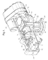
- FIG. 1 is an isometric view from above of an embodiment of the invention, including an associated swirl plate;
- FIG.2 is an isometric view like that shown in FIG. 1 but taken from the opposite side of the embodiment, showing the swirl plate and swirl valves;
- FIG. 3 is a plan view of the embodiment from above, without the swirl plate;
- FIG. 4 is a plan view of the embodiment from below, without the swirl plate;
- FIG. 5 is an isometric view of the operative mechanism contained in the embodiment as shown in FIG. 1, taken from the same point of view with the manifold omitted;
- FIG. 6 is an elevational cross-sectional view of the embodiment shown in FIGS. 1 through 5, taken along line 6-6 in FIG. 3;
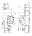
- FIG. 7 is an elevational view of the embodiment, showing the locations of various cross-sections taken in the following drawings;
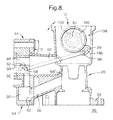
- FIG. 8 is an elevational cross-sectional view of a currently preferred arrangement of linkage between the camshaft and the swirl valve shaft contained within the intake manifold and the swirl plate, showing also the distribution of exhaust gas from the EGR valve through an exhaust gas distribution rail;
- FIG. 9 is an elevational cross-sectional view of the manifold vacuum regulation valve, taken along line 9-9 in FIG. 7;
- FIG. 10 is an elevational cross-sectional view of the exhaust gas recirculation valve, taken along line 10-10 in FIG. 7;
- FIG. 11 is a detailed elevational cross-sectional view of the manifold vacuum regulation valve, showing the incorporation of a reciprocating yoke to limit side-loading of the valve stem in its sleeve bearing;
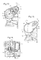
- FIG. 12 is an elevational cross-sectional view of the motor and gear train which actuates the camshaft, taken along line 12-12 in FIG. 7;
- FIG. 13 is an end view of the embodiment, taken from the electromechanical drive end;
- FIG. 14 is a cross-sectional view taken along line 14-14 in FIG. 13, showing the relationships among the drive motor, gear train, and camshaft;
- FIG. 15 is a graph showing actuation curves for the swirl valves, manifold vacuum regulation valve, and exhaust gas recirculation valve as optimized for an exemplary diesel engine;
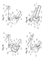
- FIGS. 16 through 19 are isometric views from above of the swirl valve control subassembly at four different stages of camshaft rotation;
- FIG. 20 is an elevational cross-sectional view of a finger follower assembly for actuating a poppet valve head, such as the MVR valve head, in accordance with the invention; and
- FIG. 21 is an elevational cross-sectional view of a finger follower assembly for actuating a poppet valve pintle, such as the EGR valve pintle, in accordance with the invention.
-
- In the following description, the embodiment is assumed to be oriented such that an associated engine is beside, and an exhaust manifold below, the embodiment. The use of the terms up, down, upper, lower, above, and below assume such an orientation.
- Referring to FIGS. 1 through 4, an integrated
intake manifold assembly 10 in accordance with the invention includes anintake manifold element 12 preferably formed as by die casting of metal such as aluminum alloy. Formed integrally withelement 12 are afirst housing 14 for aMVR valve assembly 16; asecond housing 18 for anEGR valve assembly 20; athird housing 22 for a drive motor (not visible in these drawings); afourth housing 24 for a gear train (also not visible); afifth housing 26 for alever actuator 28 attached to acamshaft 82; afirst mounting flange 30 for attachingassembly 10 to an engine block orhead 32; asecond mounting flange 34 for attachingassembly 10 to anexhaust manifold 36; and areceptacle 38 for mounting of amanifold vacuum sensor 40 having anelectrical connector 42 for conventional connection to an engine control module (ECM) (not shown). Unlike prior art intake manifolds in which MVR valves and EGR valves are assembled onto a manifold and require independent electrical actuation, position sensing, and control, the present MVR and EGR valves are integrally formed into the manifold itself and mechanically actuated by a common camshaft, as described further below. - Attached to, but separate from, integrated
intake manifold assembly 10 is aswirl valve plate 44 disposed betweenassembly 10 andengine 32.Plate 44 includesfirst ports 46, for distributing air frommanifold 12 into each of four engine cylinders (not shown) under low engine load, andsecond ports 48 in flow parallel withfirst ports 46 for providing additional air under high load conditions. Air flow frommanifold 12 throughsecond ports 48 may be regulated byswirl control valves 50 which are ganged for unified action by being mounted on asingle control shaft 52 extending through axially alignedbores 54 inplate 44. Alink 56 connectsfirst lever actuator 28 with a similar second lever actuator 58 (FIGS. 8, 18, and 19) attached toshaft 52. Whenvalves 50 are closed, air is introduced tangentially to the cylinders only viaports 46, causing a swirling motion which tends to desirably center the fuel charge on the piston. Under high air and fuel volumes, whenvalves 50 are open, such swirling is unimportant and is eliminated. - Such linkage may be attached to
actuator 28 either above the axis of rotation, as shown for example in FIGS. 1, 2, 5, and 16-19, or below the axis of rotation, as shown in FIG. 8. The currently preferred arrangement shown in FIG. 8 allows for the actuation of a swirl-port system with no linkages external to the intake manifold. All of the components of this mechanism thus may be hidden internally, within the intake manifold and swirl plate, by appropriately configuring the manifold in known fashion. After the assembly is mounted to the engine, all moving parts are concealed and protected from the environment, providing a safe, robust assembly. - Preferably,
plate 44 is also provided with alongitudinal channel 60 matable with asimilar channel 62 formed inassembly 10 to form an exhaustgas distribution rail 64 supplied with exhaust gas via anexhaust gas conduit 66 fromEGR valve assembly 20.Rail 64 is connected via individual runners (not visible) to each offirst ports 46 for dispensing exhaust gas into each of the cylinders ofengine 32. This arrangement thus accomplishes controlled exhaust gas recirculation to the cylinders without exposing the interior of the intake manifold to soot and corrosive oxides. Of course, for simplicity of construction, an integratedEGR valve assembly 20 in accordance with the invention may simply feed exhaust gas via aconduit 66' analogous toconduit 66 directly intointake manifold 12 for distribution with air into the cylinders, as in the prior art. Further, in some applications of the invention to spark-ignited gasoline powered engines, the swirl plate is not needed and distribution of EGR to the individual cylinders is not required, in whichcase assembly 10 is mounted directly ontoengine 32, andconduit 66' represents the preferred embodiment. - In gasoline engines throttled by variable valve lift,
valve assembly 16 may function as a manifold vacuum regulating valve, substantially as in a diesel engine as described herein. However, in gasoline engines throttled conventionally by a manifold inlet valve, an integrated intake manifold assembly in accordance with the invention may be usefully adapted for conventional throttle control byvalve assembly 16. - Referring to FIGS. 5, 6, 13, and 14, the
mechanism 68 of the invention is housed in the various integrated housings formed inmanifold 12, as recited above. - The power train is a conventional motor and reduction gear train. A single
brush DC motor 70, housed inthird housing 22, is provided with afirst pinion gear 72 which meshes withfirst ring gear 74 mounted on anidle shaft 76.Second pinion gear 78, attached tofirst ring gear 74, meshes withsecond ring gear 80 which is mounted oncamshaft 82 via anoutput spring 84. Acamshaft position sensor 79 is disposed on theproximal end 81 ofcamshaft 82. The gear train and position sensor are housed in acover 83 boltable to the intake manifold. Anelectrical connector 85 provides power and operating signals to the motor and carries information fromposition sensor 79 to the ECM. -
Camshaft 82 is journalled in three sets ofball bearings 87 retained in bearing mounts formed inintake manifold 12 and rotates about anaxis 77.MVR cam 86 andEGR cam 88, having throughbores, are mounted oncamshaft 82 at predetermined axial locations and at a predetermined angular relationship to each other. After the cams have been properly positioned during assembly, they are fixed in place byset screws 90. Preferably, after assembly and testing, the cams are drilled and pinned 91 to the camshaft. - Referring also to FIGS. 9 and 11, manifold vacuum regulating
valve assembly 16 includes apoppet valve head 92 for mating withseat 94 formed integrally withmanifold 12.Seat 94 is formed in abore 96 defining an air inlet tomanifold 12. Avalve pintle 98 extends from the underside ofpoppet head 92 and is received in apintle bearing insert 100 disposed in acylindrical boss 102 formed inmanifold 12 for guiding the pintle and head along a first axis ofmotion 103 orthogonal tocamshaft axis 77 during actuation of the valve. Areturn spring 104 surroundsboss 102 and is seated against a step inboss 102 for urginghead 92 towardseat 94, to a normally-closed position.Poppet valve head 92 is further provided with a slot and transverse bore for receiving aroller 106 and pin 107 for following the surface ofMVR cam 86. In FIGS. 5, 6, 9, and 11,MVR valve assembly 16 is shown in the open position, permitting the passage of air through inlet bore 96 intointake manifold 12. - Preferably,
spring 104 is selected and the valve head and seat are constructed such thatassembly 16 is fully closed when the engine is shut down. This prevents entry of additional air into the engine, important for some gasoline engines in preventing the well-known "diesel" effect of continued compressive running after the ignition is off. Prior art butterfly-type manifold entry valves are incapable of providing this advantage. Additionally, the spring strength ofspring 104 is preferably selected such that, in the event of valve control failure, the valve can be forced open by air compressed by a diesel supercharger and the engine can continue to run although non-optimally. - Referring again to FIGS. 5 and 6, and additionally FIG. 10, exhaust gas
recirculation valve assembly 20 includes apoppet valve head 108 for mating withseat 110 inserted into astep 112 in a bell-shapedvalve body 114 formed integrally withmanifold 12.Body 114 terminates at its lower end inflange 34, as recited above, for mounting ontoexhaust manifold 36. Avalve pintle 116 extends throughpoppet head 108 and is secured thereto bynut 109, which sets the tolerance stack-up in the valve assembly. Further,pintle 116 extends from the upper side ofpoppet head 108 and is received in a steppedbore 118 formed inmanifold 12 for guiding the pintle and head along a second axis ofmotion 119 orthogonal tocamshaft axis 77 during actuation of the valve. Areturn spring 120 surroundspintle 116 and is captured between apintle bearing insert 122 and anannular flange 124 onpintle 116 for urginghead 108 towardseat 110, to a normally-closed position. The upper end ofpintle 116 is further provided with a slot and transverse bore for receiving aroller 126 and pin 127 for following the surface ofEGR cam 88. Referring again to FIG. 8,first conduit 66 connectsEGR valve assembly 20 to exhaustgas rail 64. In FIGS. 5, 6, and 10,EGR valve assembly 20 is shown in the closed position, preventing the passage of exhaust gas throughflange 34 intoexhaust gas rail 64. - Referring to FIG. 10, preferably
EGR cam 88 is provided with ahook portion 128 which engages and capturesroller 126 whencam 88 is rotated sufficiently counterclockwise, thereby mechanically lockingassembly 20 in a closed position. - Referring again to FIGS. 5, 6, and 11, each of valve poppets in
assemblies yoke element 130 extending from either the valve head (MVR valve head 92) or the valve pintle (EGR valve pintle 116) towardcamshaft 82 and terminating inflat fork tines 132 which embrace the camshaft and preferably are slidingly fitted against theirrespective cam lobes strap 134, as shown in FIG. 11. The tines thus provide lateral support to the valve pintles 98,116 at their upper ends and thereby inhibit side loading of the pintles by the rotary action of the cam lobes. This reduces wear on the pintles and pintle bearings and increases the working life and reliability of the valves. - FIG. 15 shows the operation of an integrated intake manifold assembly in accordance with the invention. Exemplary actuation curves for the
swirl valve shaft 52,MVR valve 16, andEGR valve 20 are shown for a typical diesel engine application. Also refer to FIGS. 16 through 19 wherein the accompanying action of the swirlvalve control subassembly 138 is shown. Relative valve position is shown in FIG. 15 as a function of camshaft position. Arbitrarily, the curves represent full engine speed at the far left (270° of camshaft rotation) and engine shutdown at the far right (0° of camshaft rotation). - Beginning at maximum engine speed and air flow, shown at the far left of FIG. 15, the swirl valves 50 (FIG. 16) and the MVR are fully open. There is no exhaust gas recirculation. The EGR valve is both closed and locked shut by
hook 128 to prevent its being forced open by high intake manifold pressures from the engine turbocharger which would limit the effectiveness of the turbocharger. - Because
first lever actuator 28 has an arcuate slotted opening 136 for connection to link 56, the camshaft and swirlcontrol body 140 are able to rotate counterclockwise sufficiently (about 20°) to unlock the EGR valve beforelink 56 becomes engaged in controlling the swirl valves.First torsion spring 142 is disposed in torsional compression onbody 140 betweennotch 144 and pin extension 146 (see also FIG. 5), thus urginglink 56 toward the valve-closed position shown in FIGS. 16 and 17.Second torsion spring 148 is also disposed in torsional compression onbody 140 betweenlever actuator 28 and a recess in manifold 12 (not shown) but is counter-wound fromspring 142.Spring 148 urges actuator 28 counterclockwise as seen in FIGS. 16-19 (springs omitted or partially omitted in FIGS. 17-19 for clarity). -
Camshaft 82 is provided with aradial tang 150 which can engage anaxial tang 152 extending frombody 140. In the 0° camshaft position shown in FIG. 16,body 140 andactuator 28 are are rotated by the camshaft such that the EGR valve is both closed and locked shut byhook 128, as shown in FIG. 10. - As engine load is decreased (camshaft begins to rotate counterclockwise), the EGR valve is unlocked in the first 25° of rotation. Because
first lever actuator 28 has arcuate slotted opening 136 for connection to link 56, the camshaft is able to rotate clockwise sufficiently to unlock the EGR valve without beginning to close the swirl valves, as shown in FIG. 17.Link 56 becomes engaged byactuator 28 at the right end ofslot 136. - Between about 25° and 45° of rotation, link 56 is drawn counterclockwise by actuating
lever 28, closing the swirl valves completely, as shown in FIG. 18, and the engine thus becomes supplied with air solely through first ports 46 (FIG. 2). The link is now prevented by the closing of the swirl valves from traveling farther, so further rotation ofbody 140 is prevented; the camshaft, however, may continue to be rotated withinbody 140, asbody 140 is rotatably disposed on sealed bearings 141 (FIG. 6) mounted oncamshaft 82. As camshaft rotation continues,tang 150 separates fromtang 152, as shown in FIG. 19. - At about 50° of camshaft rotation, the EGR valve begins to open, adding exhaust gas to the air entering the cylinders. The MVR valve remains wide open until about 90° of rotation, then begins to close. Because the MVR valve is a poppet valve rather than a conventional rotary butterfly valve, the open area of the valve between the seat and head is cylindrical and therefore flow through the valve is linear with respect to pintle motion, and the slope of the curve is readily controlled by appropriately shaping the MVR cam lobe.
- The normal operating range of the engine is typically between cam positions of about 100° and 150°. Beyond about 180°, the MVR valve is fully closed (no fresh air is being admitted to the engine) and the EGR valve is fully open. Such a condition may be useful during non-combustive periods, such as going downhill, when fuel is withheld from the cylinders and recirculation of stale exhaust gas can progressively cool the engine cylinders.
- Finally, at engine shutdown, the camshaft is rotated to about 270° to the position shown in FIG. 19 and the swirl, MVR, and EGR valves are closed. When the engine is restarted, the camshaft is automatically rotated clock wise through a predetermined angle to provide optimal opening settings for the MVR and EGR valves, the swirl valves remaining closed until high engine speed is again required.
- Referring to FIGS. 20 and 21, side-loading of the valve poppets 155,157 alternatively may be eliminated (instead of employing
yokes 130 as described hereinabove) by displacing the axis of the valve assembly and poppet from intersecting the axis of the camshaft and installing afinger follower 154 between the cam lobe and the poppet, similar to the fashion in which engine intake valves are actuated. Thepad 156 of the finger follower, because it is pivoted from aremote pivot 158, preferably a conventional hydraulic lashadjuster 160, has an actuation path which is essentially linear over the length of the valve stroke. Thus, substantially all side-loading of the poppet within its bearing, as shown in FIGS. 9 and 10, is eliminated. Preferably,finger follower 154 includes aroller 162, analogous to rollers 106,126, for following the surface of the actuating cam lobe. Preferably, rollers 106,126 are excluded from this embodiment.MVR poppet 155 may include apintle extension 164 for optimal positioning of said valve within saidmanifold 12. - All the recited camshaft positions are programmed into a conventional engine control module in known fashion, which module receives various engine inputs including manifold pressure signals from
sensor 40 and cam position signals fromsensor 79. The ECM controls the action ofmotor 70 responsive to these and other signals and algorithms stored therein. - While the invention has been described by reference to various specific embodiments, it should be understood that numerous changes may be made within the spirit and scope of the inventive concepts described. Accordingly, it is intended that the invention not be limited to the described embodiments, but will have full scope defined by the language of the following claims.
Claims (5)
- An integrated intake manifold assembly (10) for an internal combustion engine (32), comprising:a) an intake manifold (12) attachable to said engine for providing combustion air thereto;b) an inlet valve assembly (16) having a valve body formed in said intake manifold for regulating flow of air into said manifold;c) an exhaust gas recirculation valve assembly (20) having a valve body formed in said intake manifold for regulating flow of recirculated exhaust gas into said engine, at least one of said inlet valve assembly and said exhaust gas recirculation valve assembly including a valve poppet (92,108);d) a camshaft (82) rotatably disposed on said intake manifold and having at least one cam lobe (86,88) engageable with said at least one valve poppet for controllably actuating said valve; ande) at least one finger follower (154) pivotably disposed on said intake manifold and extending between said at least one cam lobe and said at least one valve poppet for actuating said at least one poppet in response to motion of said at least one cam lobe.
- An integrated intake manifold assembly in accordance with Claim 1 wherein said at least one finger follower includes a roller (162) for following the surface of said at least one cam lobe.
- An integrated intake manifold assembly in accordance with Claim 1 wherein said valve poppet is an inlet valve poppet (92).
- An integrated intake manifold assembly in accordance with Claim 1 wherein said valve poppet is an exhaust gas recirculation valve poppet (108).
- An internal combustion engine, comprising an air intake manifold assembly (10) including
an intake manifold (12) attached to said engine for providing combustion air thereto,
an inlet valve assembly (16) having a valve body formed in said intake manifold for regulating flow of air into said manifold,
an exhaust gas recirculation valve assembly (20) having a valve body formed in said intake manifold for regulating flow of recirculated exhaust gas into said engine, at least one of said inlet valve assembly and said exhaust gas recirculation valve assembly including a valve poppet (92,108),
a camshaft (82) rotatably disposed on said intake manifold and having at least one cam lobe (86,88) engageable with said at least one valve poppet for controllably actuating said valve, and
at least one finger follower (154) pivotably disposed on said intake manifold and extending between said at least one cam lobe and said at least one valve poppet for actuating said at least one poppet in response to motion of said at least one cam lobe.
Applications Claiming Priority (2)
| Application Number | Priority Date | Filing Date | Title |
|---|---|---|---|
| US30173401P | 2001-06-28 | 2001-06-28 | |
| US301734P | 2001-06-28 |
Publications (3)
| Publication Number | Publication Date |
|---|---|
| EP1270920A2 true EP1270920A2 (en) | 2003-01-02 |
| EP1270920A3 EP1270920A3 (en) | 2004-01-07 |
| EP1270920B1 EP1270920B1 (en) | 2008-06-18 |
Family
ID=23164632
Family Applications (5)
| Application Number | Title | Priority Date | Filing Date |
|---|---|---|---|
| EP02077218A Withdrawn EP1270924A3 (en) | 2001-06-28 | 2002-06-06 | Integrated intake manifold assembly for an internal combustion engine |
| EP02077244A Withdrawn EP1270905A3 (en) | 2001-06-28 | 2002-06-10 | Manifold inlet valve having linear response |
| EP02077242A Expired - Fee Related EP1270920B1 (en) | 2001-06-28 | 2002-06-10 | Finger follower for a cam-actuated poppet valve in an engine intake manifold assembly |
| EP02077243A Pending EP1270897A3 (en) | 2001-06-28 | 2002-06-10 | Poppet valve having an aligning yoke |
| EP02077245A Expired - Lifetime EP1270898B1 (en) | 2001-06-28 | 2002-06-10 | Swirl port system for a diesel engine |
Family Applications Before (2)
| Application Number | Title | Priority Date | Filing Date |
|---|---|---|---|
| EP02077218A Withdrawn EP1270924A3 (en) | 2001-06-28 | 2002-06-06 | Integrated intake manifold assembly for an internal combustion engine |
| EP02077244A Withdrawn EP1270905A3 (en) | 2001-06-28 | 2002-06-10 | Manifold inlet valve having linear response |
Family Applications After (2)
| Application Number | Title | Priority Date | Filing Date |
|---|---|---|---|
| EP02077243A Pending EP1270897A3 (en) | 2001-06-28 | 2002-06-10 | Poppet valve having an aligning yoke |
| EP02077245A Expired - Lifetime EP1270898B1 (en) | 2001-06-28 | 2002-06-10 | Swirl port system for a diesel engine |
Country Status (3)
| Country | Link |
|---|---|
| US (5) | US6758196B2 (en) |
| EP (5) | EP1270924A3 (en) |
| DE (2) | DE60227133D1 (en) |
Families Citing this family (97)
| Publication number | Priority date | Publication date | Assignee | Title |
|---|---|---|---|---|
| AU2001259388B2 (en) * | 2000-05-03 | 2005-05-05 | Hanon Systems | EGR valve apparatus |
| EP1270924A3 (en) | 2001-06-28 | 2004-01-07 | Delphi Technologies, Inc. | Integrated intake manifold assembly for an internal combustion engine |
| DE10217695A1 (en) * | 2002-04-20 | 2003-11-13 | Daimler Chrysler Ag | Starting method for IC engine using adjustment of closure timing of engine intake valves and selective closure of intake channel for each engine cylinder |
| US6863048B2 (en) | 2002-06-12 | 2005-03-08 | Delphi Technologies, Inc. | Vacuum system for engine with variable valve lift |
| US6866020B2 (en) * | 2002-06-12 | 2005-03-15 | Delphi Technologies, Inc. | Vacuum management system for engine with variable valve lift |
| US6962138B2 (en) * | 2002-09-06 | 2005-11-08 | Delphi Technologies, Inc. | Throttle control for a small engine |
| JP4015528B2 (en) * | 2002-10-21 | 2007-11-28 | 愛三工業株式会社 | Exhaust gas recirculation device for internal combustion engine |
| US20040165798A1 (en) * | 2003-02-26 | 2004-08-26 | Valdespino Jorge A. | Eccentric bearing for a poppet drive system |
| EP1457651A2 (en) * | 2003-03-10 | 2004-09-15 | Hitachi, Ltd. | Mixture supply device for internal-combustion engine |
| US7880258B2 (en) * | 2003-05-05 | 2011-02-01 | Udt Sensors, Inc. | Thin wafer detectors with improved radiation damage and crosstalk characteristics |
| US7279731B1 (en) * | 2006-05-15 | 2007-10-09 | Udt Sensors, Inc. | Edge illuminated photodiodes |
| US7256470B2 (en) * | 2005-03-16 | 2007-08-14 | Udt Sensors, Inc. | Photodiode with controlled current leakage |
| US7655999B2 (en) * | 2006-09-15 | 2010-02-02 | Udt Sensors, Inc. | High density photodiodes |
| US8686529B2 (en) | 2010-01-19 | 2014-04-01 | Osi Optoelectronics, Inc. | Wavelength sensitive sensor photodiodes |
| US7656001B2 (en) | 2006-11-01 | 2010-02-02 | Udt Sensors, Inc. | Front-side illuminated, back-side contact double-sided PN-junction photodiode arrays |
| US8519503B2 (en) | 2006-06-05 | 2013-08-27 | Osi Optoelectronics, Inc. | High speed backside illuminated, front side contact photodiode array |
| US7576369B2 (en) * | 2005-10-25 | 2009-08-18 | Udt Sensors, Inc. | Deep diffused thin photodiodes |
| US7057254B2 (en) * | 2003-05-05 | 2006-06-06 | Udt Sensors, Inc. | Front illuminated back side contact thin wafer detectors |
| US8035183B2 (en) * | 2003-05-05 | 2011-10-11 | Udt Sensors, Inc. | Photodiodes with PN junction on both front and back sides |
| US8120023B2 (en) * | 2006-06-05 | 2012-02-21 | Udt Sensors, Inc. | Low crosstalk, front-side illuminated, back-side contact photodiode array |
| US7709921B2 (en) | 2008-08-27 | 2010-05-04 | Udt Sensors, Inc. | Photodiode and photodiode array with improved performance characteristics |
| US6988473B2 (en) * | 2003-06-26 | 2006-01-24 | Delphi Technologies, Inc. | Variable valve actuation mechanism having an integrated rocker arm, input cam follower and output cam body |
| US6978754B2 (en) * | 2003-07-31 | 2005-12-27 | Daimlerchrysler Corporation | Manifold sensor retention system |
| DE10341393B3 (en) * | 2003-09-05 | 2004-09-23 | Pierburg Gmbh | Air induction port system for internal combustion engines has exhaust gas return passage made in one piece with casing, and exhaust gas return valve and throttle valve are constructed as cartridge valve for insertion in holes in casing |
| US6935321B1 (en) * | 2004-03-17 | 2005-08-30 | Deere & Company | EGR/air mixing intake manifold with dual orientations |
| EP1605154A3 (en) | 2004-06-12 | 2011-06-22 | BorgWarner, Inc. | Integrated valve |
| US7204240B2 (en) * | 2004-06-12 | 2007-04-17 | Borgwarner Inc. | Integrated valve |
| US7537054B2 (en) * | 2004-07-02 | 2009-05-26 | Halliburton Energy Services, Inc. | Cement compositions comprising high aspect ratio materials and methods of use in subterranean formations |
| US20060157244A1 (en) * | 2004-07-02 | 2006-07-20 | Halliburton Energy Services, Inc. | Compositions comprising melt-processed inorganic fibers and methods of using such compositions |
| US20060184386A1 (en) * | 2004-07-02 | 2006-08-17 | Merritt Jeffrey R | Methods and systems for providing combination gift card and greeting card |
| DE102005023202A1 (en) * | 2004-10-02 | 2006-09-07 | Schaeffler Kg | Phaser |
| US7069919B1 (en) * | 2005-01-06 | 2006-07-04 | Caterpillar Inc | Method and apparatus for controlling the ratio of ambient air to recirculated gases in an internal combustion engine |
| KR20070108948A (en) | 2005-03-08 | 2007-11-13 | 보르그워너 인코퍼레이티드 | Egr valve having rest position |
| US7237531B2 (en) * | 2005-06-17 | 2007-07-03 | Caterpillar Inc. | Throttle and recirculation valves having a common planetary drive |
| JP2007024242A (en) * | 2005-07-20 | 2007-02-01 | Denso Corp | Fluid control valve device |
| JP2007024241A (en) * | 2005-07-20 | 2007-02-01 | Denso Corp | Fluid control valve |
| US7252077B2 (en) * | 2005-07-28 | 2007-08-07 | Haldex Hydraulics Ab | Sequential control valve |
| GB0522982D0 (en) * | 2005-11-10 | 2005-12-21 | Kennedy Roger | Induction regulator block |
| US7757679B2 (en) * | 2006-03-22 | 2010-07-20 | Borgwarner, Inc. | Integrated charge air and EGR valve |
| DE602007008376D1 (en) * | 2006-03-22 | 2010-09-23 | Borgwarner Inc | SECONDARY EGR MODULE WITH LOW PRESSURE |
| KR101317323B1 (en) | 2006-04-07 | 2013-10-14 | 보르그워너 인코퍼레이티드 | Actuator with integrated drive mechanism |
| US7311068B2 (en) | 2006-04-17 | 2007-12-25 | Jason Stewart Jackson | Poppet valve and engine using same |
| US7293546B1 (en) * | 2006-05-08 | 2007-11-13 | Delphi Technologies, Inc. | Charge motion control device using a single common drive shaft |
| DE102006031028A1 (en) * | 2006-07-05 | 2008-01-10 | Gustav Wahler Gmbh U. Co. Kg | Valve e.g. exhaust gas reconducting valve, operating device for internal combustion engine, has drive motor and eccentric drive for lifting operation of actuator with valve unit, and driven drive unit that is in connection with rotary drive |
| ATE443806T1 (en) * | 2006-07-06 | 2009-10-15 | Cooper Standard Automotive D | EXHAUST GAS RECIRCULATION VALVE |
| US20080098999A1 (en) * | 2006-10-31 | 2008-05-01 | International Engine Intellectual Property Company, Llc | Engine exhaust gas recirculation (egr) valve |
| US9178092B2 (en) | 2006-11-01 | 2015-11-03 | Osi Optoelectronics, Inc. | Front-side illuminated, back-side contact double-sided PN-junction photodiode arrays |
| KR101211758B1 (en) * | 2007-01-10 | 2012-12-12 | 엘지전자 주식회사 | Method for generating block data in wireless communication system |
| US20080314037A1 (en) * | 2007-06-20 | 2008-12-25 | Jacobus Neels | Exhaust Gas Diverter |
| US20100053802A1 (en) * | 2008-08-27 | 2010-03-04 | Masaki Yamashita | Low Power Disk-Drive Motor Driver |
| DE102007054769A1 (en) * | 2007-11-16 | 2009-05-20 | Bosch Mahle Turbo Systems Gmbh & Co. Kg | Actuator for bidirectional actuator |
| FR2926126B1 (en) * | 2008-01-03 | 2016-07-29 | Valeo Systemes De Controle Moteur | VALVE THREE WAYS |
| DE102008005591A1 (en) | 2008-01-22 | 2009-07-23 | Bayerische Motoren Werke Aktiengesellschaft | Valve device for an exhaust gas recirculation device |
| US8206133B2 (en) * | 2008-08-12 | 2012-06-26 | GM Global Technology Operations LLC | Turbocharger housing with integral inlet and outlet openings |
| EP2335288A4 (en) | 2008-09-15 | 2013-07-17 | Osi Optoelectronics Inc | Thin active layer fishbone photodiode with a shallow n+ layer and method of manufacturing the same |
| US11010841B2 (en) | 2008-10-02 | 2021-05-18 | Ecoatm, Llc | Kiosk for recycling electronic devices |
| US10853873B2 (en) | 2008-10-02 | 2020-12-01 | Ecoatm, Llc | Kiosks for evaluating and purchasing used electronic devices and related technology |
| US7881965B2 (en) | 2008-10-02 | 2011-02-01 | ecoATM, Inc. | Secondary market and vending system for devices |
| CA2739633C (en) | 2008-10-02 | 2016-06-21 | Mark Bowles | Secondary market and vending system for devices |
| DE102008057128A1 (en) * | 2008-11-13 | 2010-05-20 | Gustav Wahler Gmbh U. Co. Kg | Valve device for controlling an exhaust gas flow recirculated and supplied by an internal combustion engine |
| KR101004255B1 (en) | 2008-11-28 | 2011-01-03 | 쌍용자동차 주식회사 | intake manifold combination EGR and swirl system for automobile |
| KR20100064889A (en) * | 2008-12-05 | 2010-06-15 | 현대자동차주식회사 | Exhaust gas recirculation system with unified cylinder head and exhaust gas recirculation device |
| JP4705153B2 (en) * | 2008-12-26 | 2011-06-22 | 株式会社日本自動車部品総合研究所 | Exhaust gas recirculation device |
| US8056545B2 (en) * | 2009-01-06 | 2011-11-15 | Ford Global Technologies | Integrated cover and exhaust gas recirculation cooler for internal combustion engine |
| DE102009018378A1 (en) * | 2009-04-18 | 2010-10-21 | Mahle International Gmbh | Suction module with integrated exhaust gas recirculation |
| US8399909B2 (en) | 2009-05-12 | 2013-03-19 | Osi Optoelectronics, Inc. | Tetra-lateral position sensing detector |
| GB2473486B (en) * | 2009-09-14 | 2015-09-02 | Gm Global Tech Operations Inc | Method for diagnosing the integrity of a swirl generating system for an internal combustion engine |
| ITBO20090702A1 (en) * | 2009-10-28 | 2011-04-28 | Magneti Marelli Spa | MIXER DEVICE FOR A LOW-PRESSURE ENGINE EGR SYSTEM WITH INTERNAL COMBUSTION |
| US20110114067A1 (en) * | 2009-11-18 | 2011-05-19 | Gm Global Technology Operations, Inc. | Engine including valve lift assembly for internal egr control |
| FR2954414B1 (en) * | 2009-12-21 | 2013-09-13 | Valeo Systemes Thermiques | INTERFACE PIECE BETWEEN A CYLINDER HEAD OF A MOTOR VEHICLE ENGINE AND A HEAT EXCHANGER. |
| DE102010002233A1 (en) * | 2010-02-23 | 2011-08-25 | Behr GmbH & Co. KG, 70469 | Device for exhaust gas recirculation for an internal combustion engine |
| EP2497921A1 (en) * | 2011-03-08 | 2012-09-12 | Delphi Automotive Systems Luxembourg SA | Throttle valve assembly |
| DE102011001535A1 (en) * | 2011-03-24 | 2012-09-27 | Pierburg Gmbh | Automotive exhaust gas recirculation valve assembly |
| DE102012102615B4 (en) | 2011-03-30 | 2023-05-17 | Minebea Mitsumi Inc. | radiator thermostat |
| DE102011103518A1 (en) * | 2011-06-07 | 2012-12-13 | Mtu Friedrichshafen Gmbh | Blow-off valve for turbine of exhaust gas turbocharger mounted in internal combustion engine, has cam gear which converts rotational movement of drive element to translational movement of valve plate |
| KR101237941B1 (en) | 2012-09-26 | 2013-02-28 | 캄텍주식회사 | A egr valve for a vechicle |
| FR2990726B1 (en) * | 2012-05-15 | 2015-08-21 | Valeo Sys Controle Moteur Sas | TWO-WAY DOSER AND APPLICATIONS OF THE SAME |
| US9719884B2 (en) | 2012-12-20 | 2017-08-01 | Robert Bosch Gmbh | Intake gas sensor for internal combustion engine |
| US8912615B2 (en) | 2013-01-24 | 2014-12-16 | Osi Optoelectronics, Inc. | Shallow junction photodiode for detecting short wavelength light |
| CN103147881A (en) * | 2013-03-12 | 2013-06-12 | 第一拖拉机股份有限公司 | Force-closure eccentric cam transmission mechanism for EGR |
| CN103334853A (en) * | 2013-06-03 | 2013-10-02 | 第一拖拉机股份有限公司 | Embedded combined electric EGR valve |
| EP2884086B1 (en) * | 2013-12-11 | 2017-12-20 | Borgwarner Inc. | Actuator with valve return |
| CN103835841B (en) * | 2014-02-25 | 2016-12-07 | 长城汽车股份有限公司 | EGR valve controls device and has its vehicle |
| CA2964214C (en) | 2014-10-02 | 2020-08-04 | ecoATM, Inc. | Wireless-enabled kiosk for recycling consumer devices |
| ES2870629T3 (en) | 2014-10-02 | 2021-10-27 | Ecoatm Llc | App for device evaluation and other processes associated with device recycling |
| DE102016100193A1 (en) * | 2016-01-06 | 2017-07-06 | Hanon Systems | Arrangement and method for actuating actuators |
| US9771901B2 (en) * | 2016-01-14 | 2017-09-26 | Hyundai Kefico Corporation | Exhaust gas recirculation valve having cam structure for vehicle |
| US10269110B2 (en) | 2016-06-28 | 2019-04-23 | Ecoatm, Llc | Methods and systems for detecting cracks in illuminated electronic device screens |
| CN106812634B (en) * | 2017-01-25 | 2022-11-22 | 神通科技集团股份有限公司 | Integrated EGR valve structure on plastic intake manifold |
| KR102000758B1 (en) * | 2017-05-23 | 2019-07-17 | 이래에이엠에스 주식회사 | Integrated back pressure and egr valve module |
| US10513936B2 (en) * | 2018-04-02 | 2019-12-24 | Garrett Transportation I Inc. | Turbine housing for turbocharger with linear A/R distribution and nonlinear area distribution |
| KR20210126068A (en) | 2019-02-12 | 2021-10-19 | 에코에이티엠, 엘엘씨 | Kiosks for evaluating and purchasing used electronic devices |
| US11462868B2 (en) | 2019-02-12 | 2022-10-04 | Ecoatm, Llc | Connector carrier for electronic device kiosk |
| CA3130587A1 (en) | 2019-02-18 | 2020-08-27 | Ecoatm, Llc | Neural network based physical condition evaluation of electronic devices, and associated systems and methods |
| US11922467B2 (en) | 2020-08-17 | 2024-03-05 | ecoATM, Inc. | Evaluating an electronic device using optical character recognition |
| CA3192483A1 (en) * | 2020-08-17 | 2022-02-24 | Ecoatm, Llc | Connector carrier for electronic device kiosk |
| US11708807B1 (en) | 2022-07-25 | 2023-07-25 | Ford Global Technologies, Llc | Systems for a cooler |
Citations (4)
| Publication number | Priority date | Publication date | Assignee | Title |
|---|---|---|---|---|
| US4027636A (en) * | 1975-05-26 | 1977-06-07 | Nissan Motor Co., Ltd. | Flow rate control apparatus in exhaust gas recirculation system |
| EP0780565A2 (en) * | 1995-12-21 | 1997-06-25 | Denso Corporation | EGR system using a control valve arranged perpendicularly to the axis of an air intake passage |
| EP0900930A2 (en) * | 1997-09-04 | 1999-03-10 | General Motors Corporation | Exhaust gas recirculation valve |
| EP1103715A1 (en) * | 1999-11-29 | 2001-05-30 | Delphi Technologies, Inc. | Exhaust gas re-circulation device for an internal combustion engine |
Family Cites Families (28)
| Publication number | Priority date | Publication date | Assignee | Title |
|---|---|---|---|---|
| DE1400521A1 (en) | 1960-11-21 | 1968-10-17 | Parker Hannifin Corp | Hose coupling |
| US3675633A (en) * | 1969-01-20 | 1972-07-11 | Nissan Motor | Air-pollution preventive system for motor vehicles |
| DE2658052A1 (en) * | 1976-12-22 | 1978-07-06 | Bosch Gmbh Robert | DEVICE FOR LOAD-DEPENDENT ACTIVATION OF A CONTROL ORGAN |
| JPS5827085Y2 (en) * | 1978-05-12 | 1983-06-11 | 日産自動車株式会社 | Exhaust recirculation control device |
| JPS5654947A (en) * | 1979-10-09 | 1981-05-15 | Toyota Motor Corp | Intake and egr controller for diesel engine |
| JPS58135323A (en) * | 1982-02-05 | 1983-08-11 | Toyota Central Res & Dev Lab Inc | Air inlet device for diesel engine |
| JPS6053616A (en) * | 1983-09-01 | 1985-03-27 | Nissan Motor Co Ltd | Suction passage device for internal-combustion engine |
| US4561408A (en) * | 1984-01-23 | 1985-12-31 | Borg-Warner Corporation | Motorized flow control valve |
| JPS6228068U (en) * | 1985-08-06 | 1987-02-20 | ||
| US4846138A (en) | 1986-07-28 | 1989-07-11 | Alto Automotive, Inc. | Low profile internal combustion engine |
| DE4035176C3 (en) * | 1990-11-06 | 1997-11-13 | Freudenberg Carl Fa | Device for the metered feeding of burned gases into the combustion chamber of an internal combustion engine |
| DE19622891C2 (en) | 1996-06-07 | 1998-04-09 | Ranco Inc | Exhaust gas recirculation system |
| US5669364A (en) * | 1996-11-21 | 1997-09-23 | Siemens Electric Limited | Exhaust gas recirculation valve installation for a molded intake manifold |
| DE19725668C1 (en) * | 1997-06-18 | 1998-10-29 | Daimler Benz Ag | Exhaust gas recirculation circuit for internal combustion engine |
| DE19726162C1 (en) * | 1997-06-20 | 1999-01-28 | Bosch Gmbh Robert | Intake air distributor |
| US6012437A (en) * | 1998-07-06 | 2000-01-11 | Eaton Corporation | EGR system with improved control logic |
| US6102016A (en) * | 1999-02-12 | 2000-08-15 | Eaton Corporation | EGR system and improved actuator therefor |
| DE19929956C5 (en) * | 1999-06-29 | 2007-02-22 | Daimlerchrysler Ag | Exhaust gas recirculation valve |
| US6213447B1 (en) | 1999-07-29 | 2001-04-10 | Delphi Technologies, Inc. | Poppet value having a compliant shaft guide and compliant valve head |
| BR0013488A (en) * | 1999-08-24 | 2002-05-07 | Siemens Ag | Suction equipment for an internal combustion engine |
| US6443135B1 (en) * | 1999-10-05 | 2002-09-03 | Pierburg Aktiengesellschaft | Assembly of a valve unit, a combustion air intake and an exhaust gas recirculation unit for an internal combustion engine |
| US6230742B1 (en) | 1999-10-21 | 2001-05-15 | Delphi Technologies, Inc. | Poppet valve assembly apparatus having two simultaneously-seating heads |
| US6382195B1 (en) * | 2000-02-18 | 2002-05-07 | Borgwarner Inc. | Exhaust gas recirculation system for an internal combustion engine having an integrated valve position sensor |
| US6430929B2 (en) * | 2000-03-03 | 2002-08-13 | Honeywell International Inc. | Turbocharger with integrated exhaust gas recirculation valve |
| DE10028131C1 (en) * | 2000-06-07 | 2001-12-13 | Daimler Chrysler Ag | Exhaust gas feedback system for internal combustion engine has flange component provided with exhaust gas feedback channels leading to exhaust gas feedback line and flow control valve |
| US6390079B1 (en) * | 2000-08-21 | 2002-05-21 | Siemens Canada Limited | Exhaust gas recirculation valve including cam linkage for converting constant angular motion to non-linear motion |
| FR2818316B1 (en) * | 2000-12-15 | 2003-04-11 | Coutier Moulage Gen Ind | DEVICE FOR REGULATING THE AIR FLOW OF AN AIR INTAKE LINE OF A DIESEL ENGINE |
| EP1270924A3 (en) | 2001-06-28 | 2004-01-07 | Delphi Technologies, Inc. | Integrated intake manifold assembly for an internal combustion engine |
-
2002
- 2002-06-06 EP EP02077218A patent/EP1270924A3/en not_active Withdrawn
- 2002-06-07 US US10/164,910 patent/US6758196B2/en not_active Expired - Fee Related
- 2002-06-07 US US10/165,245 patent/US6571782B2/en not_active Expired - Fee Related
- 2002-06-07 US US10/164,900 patent/US6708677B2/en not_active Expired - Fee Related
- 2002-06-07 US US10/164,531 patent/US6772729B2/en not_active Expired - Fee Related
- 2002-06-07 US US10/165,138 patent/US6748935B2/en not_active Expired - Fee Related
- 2002-06-10 EP EP02077244A patent/EP1270905A3/en not_active Withdrawn
- 2002-06-10 EP EP02077242A patent/EP1270920B1/en not_active Expired - Fee Related
- 2002-06-10 EP EP02077243A patent/EP1270897A3/en active Pending
- 2002-06-10 EP EP02077245A patent/EP1270898B1/en not_active Expired - Lifetime
- 2002-06-10 DE DE60227133T patent/DE60227133D1/en not_active Expired - Fee Related
- 2002-06-10 DE DE60205066T patent/DE60205066T2/en not_active Expired - Fee Related
Patent Citations (4)
| Publication number | Priority date | Publication date | Assignee | Title |
|---|---|---|---|---|
| US4027636A (en) * | 1975-05-26 | 1977-06-07 | Nissan Motor Co., Ltd. | Flow rate control apparatus in exhaust gas recirculation system |
| EP0780565A2 (en) * | 1995-12-21 | 1997-06-25 | Denso Corporation | EGR system using a control valve arranged perpendicularly to the axis of an air intake passage |
| EP0900930A2 (en) * | 1997-09-04 | 1999-03-10 | General Motors Corporation | Exhaust gas recirculation valve |
| EP1103715A1 (en) * | 1999-11-29 | 2001-05-30 | Delphi Technologies, Inc. | Exhaust gas re-circulation device for an internal combustion engine |
Also Published As
| Publication number | Publication date |
|---|---|
| US6708677B2 (en) | 2004-03-23 |
| US6748935B2 (en) | 2004-06-15 |
| US6772729B2 (en) | 2004-08-10 |
| US6758196B2 (en) | 2004-07-06 |
| EP1270897A2 (en) | 2003-01-02 |
| EP1270898A2 (en) | 2003-01-02 |
| EP1270898B1 (en) | 2005-07-20 |
| US20030136388A1 (en) | 2003-07-24 |
| EP1270920A3 (en) | 2004-01-07 |
| US20030010314A1 (en) | 2003-01-16 |
| EP1270920B1 (en) | 2008-06-18 |
| EP1270897A3 (en) | 2004-11-17 |
| EP1270924A2 (en) | 2003-01-02 |
| DE60205066D1 (en) | 2005-08-25 |
| EP1270898A3 (en) | 2004-01-14 |
| US20030000506A1 (en) | 2003-01-02 |
| US20030136389A1 (en) | 2003-07-24 |
| US20030000497A1 (en) | 2003-01-02 |
| EP1270905A3 (en) | 2004-01-14 |
| DE60227133D1 (en) | 2008-07-31 |
| US6571782B2 (en) | 2003-06-03 |
| EP1270905A2 (en) | 2003-01-02 |
| DE60205066T2 (en) | 2006-04-13 |
| EP1270924A3 (en) | 2004-01-07 |
Similar Documents
| Publication | Publication Date | Title |
|---|---|---|
| US6708677B2 (en) | Finger follower for a cam-actuated poppet valve in an engine intake manifold assembly | |
| US7461642B2 (en) | Rotary-actuated exhaust gas recirculation valve having a seating force attenuator | |
| EP0900930B1 (en) | Exhaust gas recirculation valve | |
| US6325043B1 (en) | Exhaust gas recirculation device | |
| US8261725B2 (en) | Low pressure EGR apparatus | |
| US8713936B2 (en) | Multi-functional valve for use in an exhaust breathing system | |
| EP1103715B1 (en) | Exhaust gas re-circulation device for an internal combustion engine | |
| US4305349A (en) | Internal combustion engine | |
| US20110116910A1 (en) | Butterfly valve for turbocharger systems | |
| EP0182473A1 (en) | Inlet system for an internal-combustion engine | |
| US8973559B2 (en) | Gear subassembly and exhaust gas recirculation system | |
| CA2730125C (en) | Exhaust gas recirculation butterfly valve | |
| EP1996811B1 (en) | Two component low pressure egr module | |
| US10473232B2 (en) | Split linkage mechanism for valve assembly | |
| EP0920580B1 (en) | Internal combustion engine with exhaust with gas recirculation | |
| US20150247465A1 (en) | Adjustment device for valve assembly | |
| WO2023004242A1 (en) | Engine rocker lever devices and systems |
Legal Events
| Date | Code | Title | Description |
|---|---|---|---|
| PUAI | Public reference made under article 153(3) epc to a published international application that has entered the european phase |
Free format text: ORIGINAL CODE: 0009012 |
|
| AK | Designated contracting states |
Kind code of ref document: A2 Designated state(s): AT BE CH CY DE DK ES FI FR GB GR IE IT LI LU MC NL PT SE TR |
|
| AX | Request for extension of the european patent |
Free format text: AL;LT;LV;MK;RO;SI |
|
| PUAL | Search report despatched |
Free format text: ORIGINAL CODE: 0009013 |
|
| AK | Designated contracting states |
Kind code of ref document: A3 Designated state(s): AT BE CH CY DE DK ES FI FR GB GR IE IT LI LU MC NL PT SE TR |
|
| AX | Request for extension of the european patent |
Extension state: AL LT LV MK RO SI |
|
| RIC1 | Information provided on ipc code assigned before grant |
Ipc: 7F 02B 31/08 B Ipc: 7F 02M 35/12 B Ipc: 7F 02M 25/07 B Ipc: 7F 02D 9/12 B Ipc: 7F 02M 35/10 A |
|
| 17P | Request for examination filed |
Effective date: 20040707 |
|
| AKX | Designation fees paid |
Designated state(s): DE FR GB IT |
|
| 17Q | First examination report despatched |
Effective date: 20070507 |
|
| GRAP | Despatch of communication of intention to grant a patent |
Free format text: ORIGINAL CODE: EPIDOSNIGR1 |
|
| GRAS | Grant fee paid |
Free format text: ORIGINAL CODE: EPIDOSNIGR3 |
|
| GRAA | (expected) grant |
Free format text: ORIGINAL CODE: 0009210 |
|
| AK | Designated contracting states |
Kind code of ref document: B1 Designated state(s): DE FR GB IT |
|
| REG | Reference to a national code |
Ref country code: GB Ref legal event code: FG4D |
|
| REF | Corresponds to: |
Ref document number: 60227133 Country of ref document: DE Date of ref document: 20080731 Kind code of ref document: P |
|
| PLBE | No opposition filed within time limit |
Free format text: ORIGINAL CODE: 0009261 |
|
| STAA | Information on the status of an ep patent application or granted ep patent |
Free format text: STATUS: NO OPPOSITION FILED WITHIN TIME LIMIT |
|
| 26N | No opposition filed |
Effective date: 20090319 |
|
| PG25 | Lapsed in a contracting state [announced via postgrant information from national office to epo] |
Ref country code: IT Free format text: LAPSE BECAUSE OF FAILURE TO SUBMIT A TRANSLATION OF THE DESCRIPTION OR TO PAY THE FEE WITHIN THE PRESCRIBED TIME-LIMIT Effective date: 20080618 |
|
| GBPC | Gb: european patent ceased through non-payment of renewal fee |
Effective date: 20090610 |
|
| REG | Reference to a national code |
Ref country code: FR Ref legal event code: ST Effective date: 20100226 |
|
| PG25 | Lapsed in a contracting state [announced via postgrant information from national office to epo] |
Ref country code: FR Free format text: LAPSE BECAUSE OF NON-PAYMENT OF DUE FEES Effective date: 20090630 |
|
| PG25 | Lapsed in a contracting state [announced via postgrant information from national office to epo] |
Ref country code: GB Free format text: LAPSE BECAUSE OF NON-PAYMENT OF DUE FEES Effective date: 20090610 |
|
| PG25 | Lapsed in a contracting state [announced via postgrant information from national office to epo] |
Ref country code: DE Free format text: LAPSE BECAUSE OF NON-PAYMENT OF DUE FEES Effective date: 20100101 |