EP1270357A2 - Federspeicherkolben - Google Patents
Federspeicherkolben Download PDFInfo
- Publication number
- EP1270357A2 EP1270357A2 EP02012425A EP02012425A EP1270357A2 EP 1270357 A2 EP1270357 A2 EP 1270357A2 EP 02012425 A EP02012425 A EP 02012425A EP 02012425 A EP02012425 A EP 02012425A EP 1270357 A2 EP1270357 A2 EP 1270357A2
- Authority
- EP
- European Patent Office
- Prior art keywords
- spring
- piston
- loaded
- loaded piston
- plastic
- Prior art date
- Legal status (The legal status is an assumption and is not a legal conclusion. Google has not performed a legal analysis and makes no representation as to the accuracy of the status listed.)
- Granted
Links
- 229910000831 Steel Inorganic materials 0.000 claims description 11
- 239000010959 steel Substances 0.000 claims description 11
- 230000005540 biological transmission Effects 0.000 claims description 2
- 230000003014 reinforcing effect Effects 0.000 abstract description 4
- 238000001746 injection moulding Methods 0.000 abstract description 2
- XAGFODPZIPBFFR-UHFFFAOYSA-N aluminium Chemical compound [Al] XAGFODPZIPBFFR-UHFFFAOYSA-N 0.000 description 13
- 229910052782 aluminium Inorganic materials 0.000 description 13
- HCHKCACWOHOZIP-UHFFFAOYSA-N Zinc Chemical compound [Zn] HCHKCACWOHOZIP-UHFFFAOYSA-N 0.000 description 12
- 229910052725 zinc Inorganic materials 0.000 description 12
- 239000011701 zinc Substances 0.000 description 12
- 238000003860 storage Methods 0.000 description 11
- 238000004519 manufacturing process Methods 0.000 description 9
- 238000005266 casting Methods 0.000 description 7
- 239000000463 material Substances 0.000 description 7
- 238000002347 injection Methods 0.000 description 5
- 239000007924 injection Substances 0.000 description 5
- 230000032683 aging Effects 0.000 description 3
- 230000007797 corrosion Effects 0.000 description 3
- 238000005260 corrosion Methods 0.000 description 3
- 238000012805 post-processing Methods 0.000 description 3
- 230000002787 reinforcement Effects 0.000 description 3
- 238000012546 transfer Methods 0.000 description 3
- 238000005516 engineering process Methods 0.000 description 2
- 238000012545 processing Methods 0.000 description 2
- 238000011161 development Methods 0.000 description 1
- 230000018109 developmental process Effects 0.000 description 1
- 230000012447 hatching Effects 0.000 description 1
- 238000010348 incorporation Methods 0.000 description 1
- 230000010354 integration Effects 0.000 description 1
- 230000007257 malfunction Effects 0.000 description 1
- 239000012528 membrane Substances 0.000 description 1
- 230000036316 preload Effects 0.000 description 1
- 238000007789 sealing Methods 0.000 description 1
- 238000012360 testing method Methods 0.000 description 1
- 210000002105 tongue Anatomy 0.000 description 1
- 239000013585 weight reducing agent Substances 0.000 description 1
Images

Classifications
-
- B—PERFORMING OPERATIONS; TRANSPORTING
- B60—VEHICLES IN GENERAL
- B60T—VEHICLE BRAKE CONTROL SYSTEMS OR PARTS THEREOF; BRAKE CONTROL SYSTEMS OR PARTS THEREOF, IN GENERAL; ARRANGEMENT OF BRAKING ELEMENTS ON VEHICLES IN GENERAL; PORTABLE DEVICES FOR PREVENTING UNWANTED MOVEMENT OF VEHICLES; VEHICLE MODIFICATIONS TO FACILITATE COOLING OF BRAKES
- B60T17/00—Component parts, details, or accessories of power brake systems not covered by groups B60T8/00, B60T13/00 or B60T15/00, or presenting other characteristic features
- B60T17/08—Brake cylinders other than ultimate actuators
- B60T17/085—Spring loaded brake actuators
-
- F—MECHANICAL ENGINEERING; LIGHTING; HEATING; WEAPONS; BLASTING
- F16—ENGINEERING ELEMENTS AND UNITS; GENERAL MEASURES FOR PRODUCING AND MAINTAINING EFFECTIVE FUNCTIONING OF MACHINES OR INSTALLATIONS; THERMAL INSULATION IN GENERAL
- F16D—COUPLINGS FOR TRANSMITTING ROTATION; CLUTCHES; BRAKES
- F16D2121/00—Type of actuator operation force
- F16D2121/02—Fluid pressure
- F16D2121/12—Fluid pressure for releasing a normally applied brake, the type of actuator being irrelevant or not provided for in groups F16D2121/04 - F16D2121/10
-
- F—MECHANICAL ENGINEERING; LIGHTING; HEATING; WEAPONS; BLASTING
- F16—ENGINEERING ELEMENTS AND UNITS; GENERAL MEASURES FOR PRODUCING AND MAINTAINING EFFECTIVE FUNCTIONING OF MACHINES OR INSTALLATIONS; THERMAL INSULATION IN GENERAL
- F16D—COUPLINGS FOR TRANSMITTING ROTATION; CLUTCHES; BRAKES
- F16D2125/00—Components of actuators
- F16D2125/02—Fluid-pressure mechanisms
- F16D2125/06—Pistons
Definitions
- the present invention relates to a spring-loaded piston for spring-loaded brake cylinders, in particular of commercial vehicles, according to claim 1.
- service brakes In practice, service brakes, spring brake, and often as Combination cylinders designated combined service brake and spring brake cylinders known. Such brake cylinders are used to actuate brake systems of vehicles, in particular commercial vehicles.
- pure spring-loaded brake cylinders act as a preloaded spring via a spring-loaded piston to a piston rod, so that a Brake can be operated.
- the service brake part of a service brake cylinder or also a combination cylinder in the brake cylinders known from practice generally a membrane which can be acted upon by compressed air and which is opposite a plate and an actuating plunger connected to the plate acts.
- the spring brake part In the case of a combination cylinder, the spring brake part is the service brake part hitched.
- Such a semi-mounted spring brake part is for example in DE 198 30 154 A1.
- a piston rod of the spring brake part acts here, which is connected to the spring-loaded piston when actuated through the spring to the diaphragm of the service brake cylinder and transmits the spring brake force by means of the plate of the service brake cylinder the actuating plunger.
- the spring is preloaded for this when the Compressed air is applied to the spring storage chamber.
- Such spring brake cylinders have one made of aluminum or zinc cast spring-loaded piston.
- these castings have the essential Disadvantage that after casting regular post-processing steps Removal of any burrs or to even out surfaces is necessary are.
- frequently required holes for fasteners for example machined or seats for sealing or slide rings or the like can be incorporated.
- They also have aluminum or zinc manufactured spring piston the disadvantage that they are due to not fully avoidable moisture corrosion or similar aging processes exposed, which can ultimately lead to malfunctions.
- Last is the production of spring-loaded pistons as aluminum or zinc castings relative expensive, with the further disadvantage that the molds are subject to high wear subject and therefore only limited quantities can be produced.
- the object of the present invention is therefore a spring-loaded piston to propose that the cost-effective without significant post-processing can be manufactured.
- the above-mentioned corrosion or the risk of aging can be kept to a minimum.
- a spring-loaded piston made of plastic for the first time which can be manufactured, for example, as a plastic injection molded part advantageous to be realized with a plastic injection mold, clearly higher quantities can be used to increase productivity, whereby Rates of increase compared to conventional aluminum or zinc casting 10 to 20 times can be achieved without additional effort. Furthermore, can in the manufacture of the spring-loaded piston from plastic a complex Post-processing is generally not necessary. Plastic injection molded parts are available from the house from smooth surfaces. Burrs that would have to be removed later, do not usually occur with plastic injection molded parts. This can reduce the manufacturing costs a spring-loaded piston made of plastic compared to the manufacturing costs of conventional spring-loaded pistons cast from aluminum or zinc, be significantly reduced.
- the first selection of plastic offers as a material
- Production of a spring-loaded piston according to the invention has the further advantage that a spring-loaded piston made of plastic has no significant aging or even a kind of corrosion due to the presence of moisture is.
- plastic for the production of the spring-loaded piston offers the further advantage of a significant weight reduction over of aluminum or zinc casting technology. This reduces the effort in terms of handling in the manufacture of an injection molded part made of plastic Spring-loaded piston and helps to transport the manufactured parts because of their smaller dimensions.
- a spring-loaded piston made of plastic offers the additional advantage that that seats for slide rings, seals or the like already after manufacture have a sufficiently high surface quality and / or seating accuracy, that the elaborate incorporation, especially with conventional aluminum or zinc castings such seats for slide rings, seals or the like are eliminated can, which in turn results both in a reduced processing time and in reflects a cost reduction.
- the spring-loaded piston according to the invention can be produced made of plastic a remarkable reduction in noise during further processing the same, since a hollow body made of plastic opposes a metallic one Hollow body can not produce any significant noise. This fact makes especially among the workers entrusted with the integration of the brake cylinder noticeable in an increase in job quality.
- a spring-loaded piston according to the invention has a preferred one Embodiment via an insert, which preferably with in the wall or in Wall sections of the spring-loaded piston is molded, and for example made of steel or a similar, suitable material that is well placed under tension can be produced without significant deformations is.
- This reinforcement insert or steel insert is largely in the Plastic-made wall of the spring-loaded piston integrated and thus encased in plastic.
- the steel insert is used advantageously for reinforced Transfer of those introduced by the spring into the spring-loaded piston Force to its transfer area for introduction or transfer into the piston rod, the steel insert is optimally designed according to its mechanical loads can be.
- Such a reinforcement insert or steel insert also offers the advantage that the wall thickness of wall sections subjected to tension of the spring-loaded piston according to the invention compared to conventional ones Spring-loaded pistons made of aluminum or cast zinc are significantly lower can be held.
- the insert extends from a piston plate section, in particular from a contact surface of a storage spring adjacent force application area in the spring-loaded piston, up to one in an annular piston center arranged power transmission area from the spring-loaded piston to a piston or a piston rod.
- the insert can in this section, for example, encircle the entire surface in a ring, but it can also as spaced, radially extending strips in the relevant Wall section to be embedded. It is also conceivable to make the insert similar to one Crown with a wreath and adjoining rays and in to mold the wall.
- the reinforcing insert is in the
- the force application area of the storage spring is curved in an arc shape and then runs relatively rectilinear or inclined at a slight angle in a ring coaxial to the main axis X and then kinks in one or more sections to essentially one annular end portion oriented perpendicular to the longitudinal direction the piston rod rests to take over the force.
- the piston rod in a preferred manner by means of a corresponding nose, which enters the piston rod from the inside intervenes, centered in their position.
- the insert shows in a preferred Embodiment a shoulder on which the spring-loaded piston-side radially inner end of the piston or the piston rod abuts.
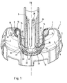
- the one out Plastic spring-loaded piston 1 has an inserted piston rod 2 on, the length of which can be adjusted depending on the required stroke and which consist of one suitable material, such as. B. aluminum or zinc or for example as an extruded Part can be made of aluminum.
- a ring-shaped, outwardly protruding web 4 recognizable on the outer circumference of the spring-loaded piston 1 .
- the web 4 can be used as a shoulder to support a not shown Sliding ring serve or function as a sliding ring itself. Further can against the web 4 if necessary seals not shown support.
- the radially outer, circumferential section of the spring-loaded piston wall can also be referred to as a guide section 5.
- a guide section 5 Within the annular cavity 6 radially delimited by the guide section 5 of the spring-loaded piston 1, which in turn is in the axial direction X by the so-called Piston plate section 7 is limited, which is not shown in Fig. 1 illustrated spring. The last turn is supported against the support area or the contact surface 8.
- Storage spring bumps or shoulders or shoulder sections 10 are provided, that protrude into the interior of the spring-loaded piston 1, that is, the cavity 6 are facing.
- the support surface 8 is further in this embodiment profiled.
- FIG. 1 an enlarged detailed view of FIG. 1 is the last turn of the storage spring 12 shown there in section radially inward on the curved contour 14 of the spring-loaded piston 1.
- the last turn of the storage spring 12 lies radially outward on the shoulder 10 on.
- the storage spring 12 lies in the axial direction X of the spring-loaded piston 1 form-fitting on the inner contour of the spring-loaded piston 1, the contact surface 8 is profiled in this area.
- the contact surface 8 has three annular grooves 16, 16 'and 16 "between which are webs 17 and 17 ', the contours of the adjacent Storage spring 12 protrude and are preferably deformable, which is an adjustment of the contact surface 8 to the contour of the storage spring when the spring brake cylinder comes in allowed.
- Fig. 1 is the one piston or the piston rod 2 receiving inner Section of the spring-loaded piston 1 is designated as region 18.
- region 18 This has one annular circumferential seat 20 which extends radially outwards into the storage spring surrounding piston wall merges, which is also referred to as a piston shirt becomes. Its radially inner section is provided with the reference number 21.
- the piston rod 2 is supported against the annular seat 20.
- the piston rod 2 held by an annular shoulder 22 from the outside.
- Another annular shoulder 24 supports the piston rod 2 from the inside.
- To the inner one Shoulder 24 are connected to integrally formed tongues or tabs 26 which extend in the axial direction X. In the embodiment shown here six such tabs 26 are provided.
- tabs 26 could also a tubular extension of the annular shoulder 24 may be provided.
- tabs 26 offer the advantage of saving material and can have a certain amount Generate spring preload.
- Within the by the piston rod 2 and the Tabs 26 defined cavity can be a release device, not shown to get integrated. This can then be against the recesses 28 of the tabs 26 support.
- the recesses 28 can also serve as abutments for clamping devices serve.
- an insert 34 is provided for reinforcing the piston skirt.
- the reinforcement 34 can be made of a material that is particularly resilient in tension, such as For example, steel or the like can be produced as a steel insert.
- the deposit follows here 34 the contour of the piston shirt.
- the steel insert 34 has at least one nose-like in the end region 40, in which it ends in the support 20 Protuberance or shoulder 42 on the centering with the piston rod 2 serves.
- the piston rod 2 is supported in the spring-loaded piston 1 against the end the end section 40 of the steel insert 34.
- One of the storage spring 12 in the support area 8 The force introduced is via the piston skirt and the integrated one Steel insert 34 transferred into the annular seat 20 and from this to the piston rod 2 forwarded.
- Tilting of the spring-loaded piston 1 relative to the piston rod 2 is by integrating the piston rod 2 within the annular shoulder 22 and the second annular shoulder 24 and the tabs 26 excluded.
- the outer contour or the guide section 5, the piston plate section 7 as well the piston shirt of the spring-loaded piston 1 are with the annular shoulder 22 and the annular shoulder 24 and the tabs 26 in one piece in Plastic made, which in both Fig. 1 and Fig. 2 through the use is symbolized by uniform hatching.
- the present invention thus creates for the first time a spring-loaded piston, which is made of plastic using injection molding technology, for example. Furthermore is the spring-loaded piston according to the invention in the area of the connection to the piston rod designed so that tilting of the spring-loaded piston against the piston rod is excluded and a firm connection between spring-loaded pistons and piston rod is ensured.
- the invention Spring piston still has a reinforcing insert, by means of significantly higher forces can be transmitted with smaller wall thicknesses than with conventional spring-loaded pistons.
- Last but not least is the seat or the contact surface formed in the spring-loaded piston to support the spring, that possible radial forces do not have a negative influence on the Have functionality of the spring-loaded piston.
Landscapes
- Engineering & Computer Science (AREA)
- Transportation (AREA)
- Mechanical Engineering (AREA)
- Pistons, Piston Rings, And Cylinders (AREA)
- Fluid-Damping Devices (AREA)
- Pipe Accessories (AREA)
- Steroid Compounds (AREA)
- Springs (AREA)
Abstract
Description
- Fig. 1
- eine dreidimensionale, aufgeschnittene Seitenansicht eines erfindungsgemäßen Federspeicherkolbens mit darin integrierter Kolbenstange, und
- Fig. 2
- den mittleren Bereich des in Fig. 1 gezeigten Federspeicherkolbens in einer geschnittenen, vergrößerten Darstellung.
Claims (4)
- Federspeicherkolben (1) für einen Federspeicherbremszylinder, insbesondere von Nutzfahrzeugen, dadurch gekennzeichnet, dass der Federspeicherkolben (1) aus Kunststoff hergestellt ist.
- Federspeicherkolben (1) nach Anspruch 1, dadurch gekennzeichnet, dass eine Einlage (34), insbesondere aus Stahl, mit in die Wandung des Federspeicherkolbens (1) eingeformt ist.
- Federspeicherkolben (1) nach Anspruch 2, dadurch gekennzeichnet, dass die Einlage (34) von einem Kolbentellerabschnitt (7), vorzugsweise von einem einer Anlagefläche (8) einer Speicherfeder (12) benachbarten Krafteinleitungsbereich in den Federspeicherkolben (1), bis zu einem in einem ringförmigen Kolbenzentrum (20) angeordneten Kraftüberleitungsbereich vom Federspeicherkolben (1) zu einem Kolben oder einer Kolbenstange (2) reicht.
- Federspeicherkolben (1) nach Anspruch 2 oder 3, dadurch gekennzeichnet, dass die Einlage (34) eine Schulter (42) aufweist, an der das federspeicherkolbenseitige, radial innere Ende des Kolbens oder der Kolbenstange (2) anliegt.
Applications Claiming Priority (2)
| Application Number | Priority Date | Filing Date | Title |
|---|---|---|---|
| DE10130542A DE10130542C5 (de) | 2001-06-25 | 2001-06-25 | Federspeicherkolben |
| DE10130542 | 2001-06-25 |
Publications (3)
| Publication Number | Publication Date |
|---|---|
| EP1270357A2 true EP1270357A2 (de) | 2003-01-02 |
| EP1270357A3 EP1270357A3 (de) | 2004-01-02 |
| EP1270357B1 EP1270357B1 (de) | 2006-05-10 |
Family
ID=7689341
Family Applications (1)
| Application Number | Title | Priority Date | Filing Date |
|---|---|---|---|
| EP02012425A Expired - Lifetime EP1270357B1 (de) | 2001-06-25 | 2002-06-10 | Federspeicherkolben |
Country Status (4)
| Country | Link |
|---|---|
| US (1) | US6629587B2 (de) |
| EP (1) | EP1270357B1 (de) |
| AT (1) | ATE325731T1 (de) |
| DE (2) | DE10130542C5 (de) |
Families Citing this family (5)
| Publication number | Priority date | Publication date | Assignee | Title |
|---|---|---|---|---|
| US8438967B2 (en) * | 2006-07-28 | 2013-05-14 | Norgren Gmbh | Piston portion for a piston assembly and a piston assembly |
| US8182023B2 (en) * | 2010-03-16 | 2012-05-22 | Sabic Innovative Plastics Ip B.V. | Plastically deformable spring energy management systems and methods for making and using the same |
| FR2969090A1 (fr) * | 2010-12-21 | 2012-06-22 | Bosch Gmbh Robert | Piston primaire plastique a insert fonctionnel en tole emboutie pour maitre-cylindre tandem a penetration et maitre-cylindre muni d'un tel piston |
| FR2969085B1 (fr) * | 2010-12-21 | 2013-04-12 | Bosch Gmbh Robert | Piston primaire plastique a insert pour maitre-cylindre tandem a penetration et maitre-cylindre muni d'un tel piston |
| US10184535B2 (en) * | 2016-10-05 | 2019-01-22 | Akebono Brake Industry Co., Ltd. | Polymeric brake piston with reinforcing core |
Citations (1)
| Publication number | Priority date | Publication date | Assignee | Title |
|---|---|---|---|---|
| DE19830154A1 (de) | 1997-07-22 | 1999-01-28 | Knorr Bremse Systeme | Kombinierter Betriebsbrems- und Federspeicherbremszylinder |
Family Cites Families (12)
| Publication number | Priority date | Publication date | Assignee | Title |
|---|---|---|---|---|
| US4056043A (en) * | 1975-10-28 | 1977-11-01 | Johnson Controls, Inc. | Fluid power piston actuators |
| DE2631023C2 (de) * | 1976-07-09 | 1979-08-16 | Knorr-Bremse Gmbh, 8000 Muenchen | Kombinierter Druckluft- und Federspeicherbremszylinder |
| JPS55148642A (en) * | 1979-05-10 | 1980-11-19 | Aisin Seiki Co Ltd | Reaction mechanism of toggle joint |
| DE2931360A1 (de) * | 1979-08-02 | 1981-02-19 | Knorr Bremse Gmbh | Relaisventil, insbesondere zweikreisig angesteuertes relaisventil fuer bremsanlagen von kraftfahrzeugen |
| US4831916A (en) * | 1987-06-01 | 1989-05-23 | Leigh Monstevens Keith V | Piston assembly |
| DE3727355A1 (de) * | 1987-08-17 | 1989-03-02 | Graubremse Gmbh | Membranzylinder fuer kraftfahrzeuge |
| DE4032211A1 (de) * | 1990-10-11 | 1992-04-16 | Wabco Westinghouse Fahrzeug | Bremszylinder fuer die betaetigung einer fahrzeugbremse |
| DE19534220A1 (de) * | 1995-09-15 | 1997-03-20 | Teves Gmbh Alfred | Bremskolben |
| JP2001510412A (ja) * | 1995-11-14 | 2001-07-31 | ニューウェイ アンカーロック インターナショナル,インク. | プラスチックの圧力板アッセンブリを有するスプリング式ブレーキアクチュエータ |
| DE19725240A1 (de) * | 1997-06-14 | 1998-12-17 | Itt Mfg Enterprises Inc | Druckmittelspeicher insbesondere für Hydraulikaggregate von elektronischen Bremssystemen für Kfz |
| US6382367B1 (en) * | 1999-01-28 | 2002-05-07 | Lucas Industries Plc | Actuating piston for a hydraulically and mechanically actuable, spot type disc brake |
| JP2001097206A (ja) * | 1999-09-30 | 2001-04-10 | Aisin Seiki Co Ltd | 負圧式倍力装置 |
-
2001
- 2001-06-25 DE DE10130542A patent/DE10130542C5/de not_active Expired - Fee Related
-
2002
- 2002-06-10 DE DE50206724T patent/DE50206724D1/de not_active Expired - Lifetime
- 2002-06-10 AT AT02012425T patent/ATE325731T1/de not_active IP Right Cessation
- 2002-06-10 EP EP02012425A patent/EP1270357B1/de not_active Expired - Lifetime
- 2002-06-25 US US10/178,777 patent/US6629587B2/en not_active Expired - Lifetime
Patent Citations (1)
| Publication number | Priority date | Publication date | Assignee | Title |
|---|---|---|---|---|
| DE19830154A1 (de) | 1997-07-22 | 1999-01-28 | Knorr Bremse Systeme | Kombinierter Betriebsbrems- und Federspeicherbremszylinder |
Also Published As
| Publication number | Publication date |
|---|---|
| US20030075397A1 (en) | 2003-04-24 |
| ATE325731T1 (de) | 2006-06-15 |
| DE10130542C1 (de) | 2002-08-08 |
| US6629587B2 (en) | 2003-10-07 |
| DE10130542C5 (de) | 2006-12-07 |
| DE50206724D1 (de) | 2006-06-14 |
| EP1270357B1 (de) | 2006-05-10 |
| EP1270357A3 (de) | 2004-01-02 |
Similar Documents
| Publication | Publication Date | Title |
|---|---|---|
| EP0625108B1 (de) | Kolben mit über ein halteglied einrastbarer kolbenstange | |
| EP0932774B1 (de) | Scheibenbremssattel | |
| EP2619466B1 (de) | Verfahren zum herstellen eines kugelhülsengelenks | |
| EP1611367B1 (de) | Hydraulisch dämpfendes gummibuchsenlager für vertikale montage | |
| DE102008047633A1 (de) | Kombinierter Betriebsbrems- und Federspeicherbremszylinder mit aus einem Führungsring und wenigstens einem Dichtungselement bestehenden Dichtungsanordnungen | |
| DE19960335A1 (de) | Hydraulikzylinder | |
| EP1706302B1 (de) | Hauptzylinder insbesondere für ein geregeltes bremssystem | |
| DE102013223962A1 (de) | Kolbenanordnung für eine Scheibenbremse | |
| DE19520682A1 (de) | Geberzylinder | |
| DE102007010835A1 (de) | Hydraulikzylinder, insbesondere Geberzylinder für eine hydraulische KFZ-Kupplungs- oder Bremsbetätigung, und Verfahren zur Herstellung eines Kolbens hierfür | |
| EP0607370B1 (de) | Kolben mit zentralventil für hydraulische bremsanlagen | |
| WO2019101881A2 (de) | Verbindungseinrichtung für die anbindung einer dämpfungseinheit eines fahrzeugs innerhalb einer radaufhängung des fahrzeugs | |
| EP1414613B1 (de) | Hydraulikkolben aus walzblech und verfahren zu dessen herstellung | |
| EP1270357B1 (de) | Federspeicherkolben | |
| EP0279930B1 (de) | Beatmungsvorrichtung für einen Federspeicherbremszylinder | |
| DE102020115045A1 (de) | Verriegelungseinheit | |
| EP0496044B1 (de) | Elastisches Lager, insbesondere zur Lagerung eines Federauges an einem Fahrzeugaufbau | |
| EP1270355B1 (de) | Federspeicherkolben für Federspeicherbremszylinder | |
| EP0807042A1 (de) | Geberzylinder | |
| DE102009052568A1 (de) | Dichtanordnung für einen Bremszylinder einer Fahrzeugbremsanlage | |
| DE19536610A1 (de) | Kolben | |
| EP0924442B1 (de) | Lagerbuchse und Verfahren zu ihrer Herstellung | |
| DE3323361A1 (de) | Kolben-zylinder-anordnung fuer bremsen | |
| WO2018166547A1 (de) | Spindelmutter für einen kugelgewindetrieb und verfahren zur herstellung einer spindelmutter | |
| DE2042961A1 (de) | Kugelgelenk |
Legal Events
| Date | Code | Title | Description |
|---|---|---|---|
| PUAI | Public reference made under article 153(3) epc to a published international application that has entered the european phase |
Free format text: ORIGINAL CODE: 0009012 |
|
| AK | Designated contracting states |
Kind code of ref document: A2 Designated state(s): AT BE CH CY DE DK ES FI FR GB GR IE IT LI LU MC NL PT SE TR |
|
| AX | Request for extension of the european patent |
Free format text: AL;LT;LV;MK;RO;SI |
|
| PUAL | Search report despatched |
Free format text: ORIGINAL CODE: 0009013 |
|
| AK | Designated contracting states |
Kind code of ref document: A3 Designated state(s): AT BE CH CY DE DK ES FI FR GB GR IE IT LI LU MC NL PT SE TR |
|
| AX | Request for extension of the european patent |
Extension state: AL LT LV MK RO SI |
|
| RIC1 | Information provided on ipc code assigned before grant |
Ipc: 7B 60T 13/26 B Ipc: 7B 60T 17/08 A Ipc: 7B 60T 13/38 B Ipc: 7B 60T 13/28 B Ipc: 7B 60T 13/22 B |
|
| 17P | Request for examination filed |
Effective date: 20040702 |
|
| AKX | Designation fees paid |
Designated state(s): AT BE CH CY DE DK ES FI FR GB GR IE IT LI LU MC NL PT SE TR |
|
| 17Q | First examination report despatched |
Effective date: 20041013 |
|
| GRAP | Despatch of communication of intention to grant a patent |
Free format text: ORIGINAL CODE: EPIDOSNIGR1 |
|
| RIN1 | Information on inventor provided before grant (corrected) |
Inventor name: GRAVIER, DAMIEN |
|
| RIC1 | Information provided on ipc code assigned before grant |
Ipc: B60T 13/22 19680901ALI20051201BHEP Ipc: B60T 13/38 19680901ALI20051201BHEP Ipc: F16D 65/14 19680901ALI20051201BHEP Ipc: B60T 17/08 19680901AFI20051201BHEP |
|
| GRAS | Grant fee paid |
Free format text: ORIGINAL CODE: EPIDOSNIGR3 |
|
| GRAA | (expected) grant |
Free format text: ORIGINAL CODE: 0009210 |
|
| AK | Designated contracting states |
Kind code of ref document: B1 Designated state(s): AT BE CH CY DE DK ES FI FR GB GR IE IT LI LU MC NL PT SE TR |
|
| PG25 | Lapsed in a contracting state [announced via postgrant information from national office to epo] |
Ref country code: IE Free format text: LAPSE BECAUSE OF FAILURE TO SUBMIT A TRANSLATION OF THE DESCRIPTION OR TO PAY THE FEE WITHIN THE PRESCRIBED TIME-LIMIT Effective date: 20060510 Ref country code: FI Free format text: LAPSE BECAUSE OF FAILURE TO SUBMIT A TRANSLATION OF THE DESCRIPTION OR TO PAY THE FEE WITHIN THE PRESCRIBED TIME-LIMIT Effective date: 20060510 Ref country code: NL Free format text: LAPSE BECAUSE OF FAILURE TO SUBMIT A TRANSLATION OF THE DESCRIPTION OR TO PAY THE FEE WITHIN THE PRESCRIBED TIME-LIMIT Effective date: 20060510 |
|
| REG | Reference to a national code |
Ref country code: GB Ref legal event code: FG4D Free format text: NOT ENGLISH |
|
| REG | Reference to a national code |
Ref country code: CH Ref legal event code: EP |
|
| REF | Corresponds to: |
Ref document number: 50206724 Country of ref document: DE Date of ref document: 20060614 Kind code of ref document: P |
|
| REG | Reference to a national code |
Ref country code: IE Ref legal event code: FG4D Free format text: LANGUAGE OF EP DOCUMENT: GERMAN |
|
| GBT | Gb: translation of ep patent filed (gb section 77(6)(a)/1977) |
Effective date: 20060601 |
|
| PG25 | Lapsed in a contracting state [announced via postgrant information from national office to epo] |
Ref country code: MC Free format text: LAPSE BECAUSE OF NON-PAYMENT OF DUE FEES Effective date: 20060630 Ref country code: LI Free format text: LAPSE BECAUSE OF NON-PAYMENT OF DUE FEES Effective date: 20060630 Ref country code: CH Free format text: LAPSE BECAUSE OF NON-PAYMENT OF DUE FEES Effective date: 20060630 Ref country code: BE Free format text: LAPSE BECAUSE OF NON-PAYMENT OF DUE FEES Effective date: 20060630 |
|
| REG | Reference to a national code |
Ref country code: SE Ref legal event code: TRGR |
|
| PG25 | Lapsed in a contracting state [announced via postgrant information from national office to epo] |
Ref country code: DK Free format text: LAPSE BECAUSE OF FAILURE TO SUBMIT A TRANSLATION OF THE DESCRIPTION OR TO PAY THE FEE WITHIN THE PRESCRIBED TIME-LIMIT Effective date: 20060810 |
|
| PG25 | Lapsed in a contracting state [announced via postgrant information from national office to epo] |
Ref country code: ES Free format text: LAPSE BECAUSE OF FAILURE TO SUBMIT A TRANSLATION OF THE DESCRIPTION OR TO PAY THE FEE WITHIN THE PRESCRIBED TIME-LIMIT Effective date: 20060821 |
|
| PG25 | Lapsed in a contracting state [announced via postgrant information from national office to epo] |
Ref country code: PT Free format text: LAPSE BECAUSE OF FAILURE TO SUBMIT A TRANSLATION OF THE DESCRIPTION OR TO PAY THE FEE WITHIN THE PRESCRIBED TIME-LIMIT Effective date: 20061010 |
|
| NLV1 | Nl: lapsed or annulled due to failure to fulfill the requirements of art. 29p and 29m of the patents act | ||
| ET | Fr: translation filed | ||
| REG | Reference to a national code |
Ref country code: IE Ref legal event code: FD4D |
|
| REG | Reference to a national code |
Ref country code: CH Ref legal event code: PL |
|
| PLBE | No opposition filed within time limit |
Free format text: ORIGINAL CODE: 0009261 |
|
| STAA | Information on the status of an ep patent application or granted ep patent |
Free format text: STATUS: NO OPPOSITION FILED WITHIN TIME LIMIT |
|
| 26N | No opposition filed |
Effective date: 20070213 |
|
| PG25 | Lapsed in a contracting state [announced via postgrant information from national office to epo] |
Ref country code: AT Free format text: LAPSE BECAUSE OF NON-PAYMENT OF DUE FEES Effective date: 20060610 |
|
| BERE | Be: lapsed |
Owner name: KNORR-BREMSE SYSTEME FUR NUTZFAHRZEUGE G.M.B.H. Effective date: 20060630 |
|
| PG25 | Lapsed in a contracting state [announced via postgrant information from national office to epo] |
Ref country code: GR Free format text: LAPSE BECAUSE OF FAILURE TO SUBMIT A TRANSLATION OF THE DESCRIPTION OR TO PAY THE FEE WITHIN THE PRESCRIBED TIME-LIMIT Effective date: 20060811 |
|
| PG25 | Lapsed in a contracting state [announced via postgrant information from national office to epo] |
Ref country code: LU Free format text: LAPSE BECAUSE OF NON-PAYMENT OF DUE FEES Effective date: 20060610 Ref country code: TR Free format text: LAPSE BECAUSE OF FAILURE TO SUBMIT A TRANSLATION OF THE DESCRIPTION OR TO PAY THE FEE WITHIN THE PRESCRIBED TIME-LIMIT Effective date: 20060510 |
|
| PG25 | Lapsed in a contracting state [announced via postgrant information from national office to epo] |
Ref country code: CY Free format text: LAPSE BECAUSE OF FAILURE TO SUBMIT A TRANSLATION OF THE DESCRIPTION OR TO PAY THE FEE WITHIN THE PRESCRIBED TIME-LIMIT Effective date: 20060510 |
|
| PGFP | Annual fee paid to national office [announced via postgrant information from national office to epo] |
Ref country code: SE Payment date: 20090623 Year of fee payment: 8 |
|
| PGFP | Annual fee paid to national office [announced via postgrant information from national office to epo] |
Ref country code: GB Payment date: 20090623 Year of fee payment: 8 |
|
| PGFP | Annual fee paid to national office [announced via postgrant information from national office to epo] |
Ref country code: IT Payment date: 20090627 Year of fee payment: 8 |
|
| EUG | Se: european patent has lapsed | ||
| GBPC | Gb: european patent ceased through non-payment of renewal fee |
Effective date: 20100610 |
|
| PG25 | Lapsed in a contracting state [announced via postgrant information from national office to epo] |
Ref country code: IT Free format text: LAPSE BECAUSE OF NON-PAYMENT OF DUE FEES Effective date: 20100610 |
|
| PG25 | Lapsed in a contracting state [announced via postgrant information from national office to epo] |
Ref country code: GB Free format text: LAPSE BECAUSE OF NON-PAYMENT OF DUE FEES Effective date: 20100610 |
|
| PGFP | Annual fee paid to national office [announced via postgrant information from national office to epo] |
Ref country code: FR Payment date: 20110630 Year of fee payment: 10 |
|
| PG25 | Lapsed in a contracting state [announced via postgrant information from national office to epo] |
Ref country code: SE Free format text: LAPSE BECAUSE OF NON-PAYMENT OF DUE FEES Effective date: 20100611 |
|
| REG | Reference to a national code |
Ref country code: FR Ref legal event code: ST Effective date: 20130228 |
|
| PG25 | Lapsed in a contracting state [announced via postgrant information from national office to epo] |
Ref country code: FR Free format text: LAPSE BECAUSE OF NON-PAYMENT OF DUE FEES Effective date: 20120702 |
|
| PGFP | Annual fee paid to national office [announced via postgrant information from national office to epo] |
Ref country code: DE Payment date: 20150623 Year of fee payment: 14 |
|
| REG | Reference to a national code |
Ref country code: DE Ref legal event code: R119 Ref document number: 50206724 Country of ref document: DE |
|
| PG25 | Lapsed in a contracting state [announced via postgrant information from national office to epo] |
Ref country code: DE Free format text: LAPSE BECAUSE OF NON-PAYMENT OF DUE FEES Effective date: 20170103 |