EP1269085B1 - Combination oven with three-stage water atomizer - Google Patents
Combination oven with three-stage water atomizer Download PDFInfo
- Publication number
- EP1269085B1 EP1269085B1 EP00970806A EP00970806A EP1269085B1 EP 1269085 B1 EP1269085 B1 EP 1269085B1 EP 00970806 A EP00970806 A EP 00970806A EP 00970806 A EP00970806 A EP 00970806A EP 1269085 B1 EP1269085 B1 EP 1269085B1
- Authority
- EP
- European Patent Office
- Prior art keywords
- cup
- water
- fan
- walls
- atomizer
- Prior art date
- Legal status (The legal status is an assumption and is not a legal conclusion. Google has not performed a legal analysis and makes no representation as to the accuracy of the status listed.)
- Expired - Lifetime
Links
- XLYOFNOQVPJJNP-UHFFFAOYSA-N water Substances O XLYOFNOQVPJJNP-UHFFFAOYSA-N 0.000 title claims abstract description 90
- 238000010438 heat treatment Methods 0.000 claims description 25
- 235000013305 food Nutrition 0.000 claims description 5
- 238000010008 shearing Methods 0.000 claims description 4
- 238000002360 preparation method Methods 0.000 claims description 2
- 239000008400 supply water Substances 0.000 abstract description 4
- 230000008016 vaporization Effects 0.000 abstract 2
- 238000009834 vaporization Methods 0.000 abstract 2
- 238000010411 cooking Methods 0.000 description 14
- 238000000889 atomisation Methods 0.000 description 5
- 238000005192 partition Methods 0.000 description 4
- 230000001154 acute effect Effects 0.000 description 2
- 230000006870 function Effects 0.000 description 2
- 208000004434 Calcinosis Diseases 0.000 description 1
- 241000555745 Sciuridae Species 0.000 description 1
- 238000005260 corrosion Methods 0.000 description 1
- 230000007797 corrosion Effects 0.000 description 1
- 230000002452 interceptive effect Effects 0.000 description 1
- 239000000463 material Substances 0.000 description 1
- 239000007769 metal material Substances 0.000 description 1
- 238000000034 method Methods 0.000 description 1
- 239000003595 mist Substances 0.000 description 1
- 239000007787 solid Substances 0.000 description 1
- 229910001220 stainless steel Inorganic materials 0.000 description 1
- 239000010935 stainless steel Substances 0.000 description 1
- 238000010025 steaming Methods 0.000 description 1
Images



Classifications
-
- F—MECHANICAL ENGINEERING; LIGHTING; HEATING; WEAPONS; BLASTING
- F24—HEATING; RANGES; VENTILATING
- F24C—DOMESTIC STOVES OR RANGES ; DETAILS OF DOMESTIC STOVES OR RANGES, OF GENERAL APPLICATION
- F24C15/00—Details
- F24C15/32—Arrangements of ducts for hot gases, e.g. in or around baking ovens
- F24C15/322—Arrangements of ducts for hot gases, e.g. in or around baking ovens with forced circulation
- F24C15/327—Arrangements of ducts for hot gases, e.g. in or around baking ovens with forced circulation with air moisturising
-
- F—MECHANICAL ENGINEERING; LIGHTING; HEATING; WEAPONS; BLASTING
- F22—STEAM GENERATION
- F22B—METHODS OF STEAM GENERATION; STEAM BOILERS
- F22B27/00—Instantaneous or flash steam boilers
- F22B27/16—Instantaneous or flash steam boilers involving spray nozzles for sprinkling or injecting water particles on to or into hot heat-exchange elements, e.g. into tubes
Definitions
- the present invention relates to cooking ovens, and in particular, to combination ovens and steamers.
- Combination ovens provide the ability to cook foods using steam, hot air or a combination of both.
- a motor driven fan is used to circulate air within a cooking chamber past electrical hearing elements or gas fired heat exchange tubes.
- Combination ovens can be designed with or without a boiler.
- a water line feeds water into the cooking chamber near the heating elements to vaporize the water.
- combination ovens typically feed the water within the inner diameter of the fan so that the water is drawn through the fan. Contact of the water with the fan blades separates the water into small droplets having an effective large surface area which can be vaporized more efficiently.
- some prior art combination ovens include an atomization element at the hub of the fan which is rotated by the motor. The atomization element which acts to break up the water before it is further reduced by the fan blades. This two stage atomization process produces a fine mist of water surrounding the heating elements.
- U.S. patent no. 5,014,679 One type of two stage atomizer is disclosed in U.S. patent no. 5,014,679, wherein the atomizer element is a cylindrical drum forming a trough with an open end into which the water is fed. As the drum is rotated, centrifugal force directs the water to pass through the open end where it is broken up by shear forces at the circular edge. The broken up water is then directed radially outward to a fan.
- a variation on this design includes a perforated cylindrical drum with centrifugal force directing the water out of the perforations. The water is broken up more finely in this design due to increased shearing of the water by the perforations.
- This patent discloses a combination oven in which the water is directed at an outer surface of a pre-atomizer as it is rotated.
- the pre-atomizer is a sphere, a hemisphere or a plate having no openings.
- the contact of the water with the outer surface of the rotating atomizer element preliminarily breaks up the water before it is drawn into the fan.
- a combination steam and convection oven is desired that provides improved atomization of water.
- EP-A-0 530 477 discloses an apparatus in accordance with the pre-characterising section of claim 1.
- an atomizer for use in a combination steam and convection oven for the preparation of food, the oven having a heating element and a water line for delivering water, the atomizer comprising:
- atomizer enable the provision of a combination steam and convection oven for preparing food having a three stage atomizer providing highly energy efficient steaming operation.
- An atomizer cup preliminarily breaks up impinging water at inner surfaces before it is sheared through opening in the walls and drawn into and through a fan.
- the atomizer includes a fan rotating about an axis to dispel air radially outward.
- the fan has an open face providing access to a fan interior. Heating elements surround the fan in the path of the dispelled air.
- a cup is attached to the fan along the axis within the fan interior to rotate with the fan.
- the cup has an open face providing access to a cup interior defined by axially extending cup walls, which receives water from a water line.
- the cup walls vary in distance from the axis as a function of an angle about the axis.
- At least one cup wall includes an opening through which the water in the cup interior passes. In this way, the cup walls provide impact surfaces striking and atomizing water introduced through the open face of the cup to the cup interior. The edges of the opening causes shearing of the water so as to further break up the water passing through the opening before contacting blades of the fan.
- the cup can include a plurality of openings.
- the openings can be perforations, preferably however, the openings are slots disposed along the union of adjacent walls.
- the atomizer cup has rectilinear walls defining a rectangular cross-sections.
- the walls may, however, have an N-sided cross-section where N is between 3 and 10.
- the walls can be configured to extend radially outward so that adjacent walls define water receiving pockets.
- the walls can also be curved to define concave inward pockets for receiving water. In either case, water feed into the cup interior is impacted and agitated by the cup walls, particularly at their edges, before the water exits the openings.
- the present invention provides a convection food oven having improved steam generating capabilities.
- the oven includes an oven enclosure containing a water line and at least one heating element.
- a motor-driven radial fan positioned near the heating element, rotates about a rotation axis.
- An atomizer cup is attached to a hub of the fan and has a plurality of rectilinear walls with slotted edges.
- water from the water line is atomized in three stages. In the first stage, impinging water is broken up by contact with the inside surfaces of the of walls. In the second stage, the water is sheared by passing through the slots. And, in the third stage, the water is further atomized by contacting the fan blades.
- a combination convention and steam cooking oven 10 includes an enclosure 12 defining a cooking chamber 14 for containing foodstuffs.
- the cooking chamber also includes heating elements 16 as well as an atomizer 18 comprising a motor-operated fan 20 and an atomizer cup 22 at one side of the cooking chamber 14.
- the heating elements 16 are conduits of a metallic material through which gas heated by the oven burners (not shown) circulates.
- the heating elements 16 include two sets of three conduits extending in close proximity to the outer diameter of the fan 20, preferably at each side, in front of and behind the fan 20.
- the heating elements 16 may be suitable solid resistive heating elements.
- the heating elements 16, fan 20 and atomizer cup 22 are located adjacent to a partition 24 separating the cooking chamber 14 from an electronics area 26.
- the fan 20 is a squirrel cage design having a plurality of inwardly cupped blades 28 attached at a fixed end 30 to parallel circular rims 32.
- the blades 28 are oriented to draw air in through an open side 34 and expel air radially outward toward the heating elements 16 when rotated clockwise.
- the fan 20 includes a wall 36 having a concentric opening 38 for suitably mounting the fan 20 to a motor shaft 40 positioned along a rotation axis 42.
- the motor shaft 40 also extends through an opening 44 in the partition 24 back to the electronics area 26 in which a suitable electric motor 46 is disposed.
- the motor 46 is mounted by suitable bracketry (not shown) to the partition 24.
- the motor 46 is coupled to a control module (not shown) having a suitable keypad user interface (not shown) viewable from the front exterior of the enclosure 12 for setting cooking time and temperature.
- the motor shaft 40 also mounts the atomizer cup 22 at the center of the fan 20.
- the atomizer cup 22 includes a plurality of rectilinear walls 48 joined at edges 50 defining a cup volume 52 having an open side 54 and an opposite walled side 56.
- the walled side 56 includes an opening 58 through which the motor shaft 40 is inserted.
- the atomizer cup 22 can be mounted to the motor shaft 40 by any suitable connection, such as a press-fit, threaded fastener or slot pin and connection.
- the atomizer cup 22 includes four walls 48 joined at right angles.
- the walls 48 have lengthwise slots 60 at the edges and an inwardly tapered lip 62 at the opening sides 54 to provide a trough for presenting water at the inner surfaces of the walls 48 from exiting out the open side 54 of the atomizer cup 22.
- the slots 60 are preferably sized large enough so as not be easily clogged by buildup of calcium deposits from the water.
- the walls 48 are preferably made of a material resistant to the affects of heat and corrosion, such as stainless steel.
- a water line 64 of suitable tubing extends from a fitting 66 within the electronics area 26 of the enclosure 12 at which a water supply line (not shown) is attached to a flow control valve 68, such as a solenoid, coupled to the electronic control module (not shown). From the control valve 68, the water line 64 continues through an opening 69 (see Fig. 1) in the partition 24 into the cooking chamber 14 in a suitable path to avoid interfering with the fan 20. The water line 64 terminates at an open end 70 within the cup volume 52 of the atomizer cup 22.
- the combination oven 10 can be used solely for convection cooking.
- the flow control valve 68 remains closed so that no water is fed to the atomizer 18.
- the motor 46 rotates the fan 20 to pick up and circulate heat radiating from the energized heating elements 16.
- the flow control valve 68 is operated to allow supply water to flow through the water line 64 to the atomizer 18.
- the flow control valve 68 can be controlled to provide intermittent or steady stream flow of water through the water line 64. In either case, the flow rate is controlled to provide only the volume of water that can be immediately vaporized by the heating elements 16 so that overflowing water does not accumulate at the bottom of the cooking chamber 14.
- the impinging water is broken up and directed past the heating elements 16.
- the atomizer cup 22 and fan 20 act to break up the water in three stages.
- the rotating rectilinear walls 48 disrupt and agitate the impinging water to a greater extent than smooth curvilinear surfaces.
- Second, the centrifugal force generated by rotation directs the water within the cup volume 52 radially outward to the edge slots 60. As the water passes through the slots 60 it is sheared by its edges.
- the fan 20 draws this water into contact with the revolving blades 28, which further shears the water.
- the water is broken up to increase its surface area as it passes by the heating elements 16. According to known heat transfer principles, increasing surface area of a body increases the rate at which heat is transferred to that body. Here, the water flowing from the water line 64 will be more efficiently vaporized to steam by the heating elements 16 due to the atomization of the water. Thus, the heating elements will consume less energy while generating a given amount of steam.
- Figure 5 shows an alternate embodiment of the oven 10A with an atomizer cup 22A having six rectilinear walls 48A joined at their edges 50A at alternating obtuse and acute included angles.
- the walls separated by the acute included angles define pockets 80 in which the impinging water can be captured and agitated before it is directed out edgewise slots 60A to the fan 20.
- This embodiment provides additional edges and surfaces for contacting and breaking up the impinging water prior to exiting through the slots 60.
- Figure 6 shows another embodiment of an atomizer cup 22B having four arcuate walls 48B joined at their edges 50B.
- the arcuate walls 48B define in concave interior pockets 80B, which capture and agitate water fed into the atomizer cup 22B before it is directed out slots 60B.
- This embodiment as well as that shown in Fig. 5, preferably includes an inwardly directed rim (not shown) at the open side of the atomizer cup for retaining water.
Landscapes
- Engineering & Computer Science (AREA)
- Mechanical Engineering (AREA)
- General Engineering & Computer Science (AREA)
- Chemical & Material Sciences (AREA)
- Combustion & Propulsion (AREA)
- Physics & Mathematics (AREA)
- Thermal Sciences (AREA)
- Commercial Cooking Devices (AREA)
- Cookers (AREA)
- Air Humidification (AREA)
- Electric Ovens (AREA)
Abstract
Description
- The present invention relates to cooking ovens, and in particular, to combination ovens and steamers.
- Combination ovens provide the ability to cook foods using steam, hot air or a combination of both. A motor driven fan is used to circulate air within a cooking chamber past electrical hearing elements or gas fired heat exchange tubes. Combination ovens can be designed with or without a boiler. To produce steam within the cooking chamber, a water line feeds water into the cooking chamber near the heating elements to vaporize the water.
- It is well known that the rate of thermal heat transfer increases in proportion to the surface over which the heating occurs. Thus, combination ovens typically feed the water within the inner diameter of the fan so that the water is drawn through the fan. Contact of the water with the fan blades separates the water into small droplets having an effective large surface area which can be vaporized more efficiently. To further improve thermal efficiency, some prior art combination ovens include an atomization element at the hub of the fan which is rotated by the motor. The atomization element which acts to break up the water before it is further reduced by the fan blades. This two stage atomization process produces a fine mist of water surrounding the heating elements.
- One type of two stage atomizer is disclosed in U.S. patent no. 5,014,679, wherein the atomizer element is a cylindrical drum forming a trough with an open end into which the water is fed. As the drum is rotated, centrifugal force directs the water to pass through the open end where it is broken up by shear forces at the circular edge. The broken up water is then directed radially outward to a fan. A variation on this design includes a perforated cylindrical drum with centrifugal force directing the water out of the perforations. The water is broken up more finely in this design due to increased shearing of the water by the perforations.
- An alternative design is disclosed in U.S. patent no. 5,530,223. This patent discloses a combination oven in which the water is directed at an outer surface of a pre-atomizer as it is rotated. The pre-atomizer is a sphere, a hemisphere or a plate having no openings. The contact of the water with the outer surface of the rotating atomizer element preliminarily breaks up the water before it is drawn into the fan. However, in this design, there is relatively little shear forces acting on the impinging water, compared to the perforated drum, such that the water is not as finely broken up.
- Accordingly, a combination steam and convection oven is desired that provides improved atomization of water.
- EP-A-0 530 477 discloses an apparatus in accordance with the pre-characterising section of claim 1.
- According to the present invention there is provided an atomizer for use in a combination steam and convection oven for the preparation of food, the oven having a heating element and a water line for delivering water, the atomizer comprising:
- a fan rotatable about an axis to dispel air radially therefrom and positioned to be surrounded by the heating element in a path of the dispelled air, the fan having an open face providing access to a fan interior; and
- a cup attached at the axis to the fan within the fan interior to rotate therewith, the cup having an open face providing access to a cup interior defined by axially extending cup walls arranged to receive the water from the water line, wherein at least one cup wall includes an opening through which the water in the cup interior may pass; characterised in that:
- the cup walls vary in distance from the axis as a function of an angle about the axis; and
- the cup walls provide impact surfaces for striking and atomizing water introduced through the open face of the cup to cup interior and whereby edges of the opening cause shearing of the water so as to further break up the water passing through the opening before contacting blades of the fan.
-
- The hereinafter described and illustrated preferred embodiments of atomizer enable the provision of a combination steam and convection oven for preparing food having a three stage atomizer providing highly energy efficient steaming operation. An atomizer cup preliminarily breaks up impinging water at inner surfaces before it is sheared through opening in the walls and drawn into and through a fan.
- Specifically, the atomizer includes a fan rotating about an axis to dispel air radially outward. The fan has an open face providing access to a fan interior. Heating elements surround the fan in the path of the dispelled air. A cup is attached to the fan along the axis within the fan interior to rotate with the fan. The cup has an open face providing access to a cup interior defined by axially extending cup walls, which receives water from a water line. The cup walls vary in distance from the axis as a function of an angle about the axis. At least one cup wall includes an opening through which the water in the cup interior passes. In this way, the cup walls provide impact surfaces striking and atomizing water introduced through the open face of the cup to the cup interior. The edges of the opening causes shearing of the water so as to further break up the water passing through the opening before contacting blades of the fan.
- In one aspect of the invention, the cup can include a plurality of openings. The openings can be perforations, preferably however, the openings are slots disposed along the union of adjacent walls.
- In another aspect of the invention, the atomizer cup has rectilinear walls defining a rectangular cross-sections. The walls may, however, have an N-sided cross-section where N is between 3 and 10. In this way, the walls can be configured to extend radially outward so that adjacent walls define water receiving pockets. The walls can also be curved to define concave inward pockets for receiving water. In either case, water feed into the cup interior is impacted and agitated by the cup walls, particularly at their edges, before the water exits the openings.
- In one preferred form, the present invention provides a convection food oven having improved steam generating capabilities. The oven includes an oven enclosure containing a water line and at least one heating element. A motor-driven radial fan, positioned near the heating element, rotates about a rotation axis. An atomizer cup is attached to a hub of the fan and has a plurality of rectilinear walls with slotted edges. As such, water from the water line is atomized in three stages. In the first stage, impinging water is broken up by contact with the inside surfaces of the of walls. In the second stage, the water is sheared by passing through the slots. And, in the third stage, the water is further atomized by contacting the fan blades.
- These and still other advantages of the present invention will be apparent from the description of the preferred embodiments which follow.
-
- Fig. 1 is a side view of an atomizer of the present invention and a drive unit and water feed within a combination convection and steam oven, the drive unit and water feed shown schematically;
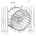
- Fig. 2 is an enlarged perspective view of an atomizer cup, fan, a water line and heating elements of the atomizer of Fig. 1;
- Fig. 3 is a side view of the atomizer of Fig. 2, shown with one set of heating elements removed;
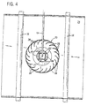
- Fig. 4 is front view of the atomizer;
- Fig. 5 is an enlarged front view of an alternate embodiment of the atomizer cup; and
- Fig. 6 is an enlarged front view of another embodiment of the atomizer cup.
-
- Referring to Fig. 1, a combination convention and
steam cooking oven 10 includes anenclosure 12 defining acooking chamber 14 for containing foodstuffs. The cooking chamber also includesheating elements 16 as well as anatomizer 18 comprising a motor-operatedfan 20 and anatomizer cup 22 at one side of thecooking chamber 14. Theheating elements 16 are conduits of a metallic material through which gas heated by the oven burners (not shown) circulates. Preferably, theheating elements 16 include two sets of three conduits extending in close proximity to the outer diameter of thefan 20, preferably at each side, in front of and behind thefan 20. Alternatively, theheating elements 16 may be suitable solid resistive heating elements. Theheating elements 16,fan 20 andatomizer cup 22 are located adjacent to apartition 24 separating thecooking chamber 14 from anelectronics area 26. - The
fan 20 is a squirrel cage design having a plurality of inwardlycupped blades 28 attached at afixed end 30 to parallelcircular rims 32. Theblades 28 are oriented to draw air in through an open side 34 and expel air radially outward toward theheating elements 16 when rotated clockwise. Opposite the open side 34, thefan 20 includes a wall 36 having a concentric opening 38 for suitably mounting thefan 20 to amotor shaft 40 positioned along arotation axis 42. - The
motor shaft 40 also extends through anopening 44 in thepartition 24 back to theelectronics area 26 in which a suitableelectric motor 46 is disposed. Preferably, themotor 46 is mounted by suitable bracketry (not shown) to thepartition 24. Themotor 46 is coupled to a control module (not shown) having a suitable keypad user interface (not shown) viewable from the front exterior of theenclosure 12 for setting cooking time and temperature. - The
motor shaft 40 also mounts theatomizer cup 22 at the center of thefan 20. In a preferred embodiment, theatomizer cup 22 includes a plurality ofrectilinear walls 48 joined atedges 50 defining acup volume 52 having anopen side 54 and an oppositewalled side 56. Thewalled side 56 includes an opening 58 through which themotor shaft 40 is inserted. Theatomizer cup 22 can be mounted to themotor shaft 40 by any suitable connection, such as a press-fit, threaded fastener or slot pin and connection. In one preferred embodiment, theatomizer cup 22 includes fourwalls 48 joined at right angles. Preferably, thewalls 48 havelengthwise slots 60 at the edges and an inwardly taperedlip 62 at the openingsides 54 to provide a trough for presenting water at the inner surfaces of thewalls 48 from exiting out theopen side 54 of theatomizer cup 22. Theslots 60 are preferably sized large enough so as not be easily clogged by buildup of calcium deposits from the water. Thewalls 48 are preferably made of a material resistant to the affects of heat and corrosion, such as stainless steel. - A
water line 64 of suitable tubing extends from a fitting 66 within theelectronics area 26 of theenclosure 12 at which a water supply line (not shown) is attached to aflow control valve 68, such as a solenoid, coupled to the electronic control module (not shown). From thecontrol valve 68, thewater line 64 continues through an opening 69 (see Fig. 1) in thepartition 24 into thecooking chamber 14 in a suitable path to avoid interfering with thefan 20. Thewater line 64 terminates at anopen end 70 within thecup volume 52 of theatomizer cup 22. - The
combination oven 10 can be used solely for convection cooking. In this case, theflow control valve 68 remains closed so that no water is fed to theatomizer 18. Themotor 46 rotates thefan 20 to pick up and circulate heat radiating from the energizedheating elements 16. When steam cooking is desired, theflow control valve 68 is operated to allow supply water to flow through thewater line 64 to theatomizer 18. Theflow control valve 68 can be controlled to provide intermittent or steady stream flow of water through thewater line 64. In either case, the flow rate is controlled to provide only the volume of water that can be immediately vaporized by theheating elements 16 so that overflowing water does not accumulate at the bottom of thecooking chamber 14. - As the
atomizer cup 22 andfan 20 are rotated, the impinging water is broken up and directed past theheating elements 16. Theatomizer cup 22 andfan 20 act to break up the water in three stages. First, water leaving thewater line 64 impinges on the inside surface of theatomizer cup walls 48. The rotatingrectilinear walls 48 disrupt and agitate the impinging water to a greater extent than smooth curvilinear surfaces. Second, the centrifugal force generated by rotation directs the water within thecup volume 52 radially outward to theedge slots 60. As the water passes through theslots 60 it is sheared by its edges. Third, thefan 20 draws this water into contact with the revolvingblades 28, which further shears the water. The water is broken up to increase its surface area as it passes by theheating elements 16. According to known heat transfer principles, increasing surface area of a body increases the rate at which heat is transferred to that body. Here, the water flowing from thewater line 64 will be more efficiently vaporized to steam by theheating elements 16 due to the atomization of the water. Thus, the heating elements will consume less energy while generating a given amount of steam. - Figure 5 shows an alternate embodiment of the oven 10A with an
atomizer cup 22A having sixrectilinear walls 48A joined at theiredges 50A at alternating obtuse and acute included angles. The walls separated by the acute included angles definepockets 80 in which the impinging water can be captured and agitated before it is directed outedgewise slots 60A to thefan 20. This embodiment provides additional edges and surfaces for contacting and breaking up the impinging water prior to exiting through theslots 60. - Figure 6 shows another embodiment of an atomizer cup 22B having four
arcuate walls 48B joined at theiredges 50B. Thearcuate walls 48B define in concaveinterior pockets 80B, which capture and agitate water fed into the atomizer cup 22B before it is directed outslots 60B. This embodiment, as well as that shown in Fig. 5, preferably includes an inwardly directed rim (not shown) at the open side of the atomizer cup for retaining water.
Claims (10)
- An atomizer (18) for use in a combination steam and convection oven (10) for the preparation of food, the oven having a heating element (16) and a water line (64) for delivering water, the atomizer comprising:characterised in that:a fan (20) rotatable about an axis (42) to dispel air radially therefrom and positioned to be surrounded by the heating element (16) in a path of the dispelled air, the fan having an open face providing access to a fan interior; anda cup (22, 22A, 22B) attached at the axis to the fan (20) within the fan interior to rotate therewith, the cup having an open face (54) providing access to a cup interior defined by axially extending cup walls (48, 48A, 48B) arranged to receive the water from the water line, wherein at least one cup wall (48) includes an opening (60) through which the water in the cup interior may pass;the cup walls vary in distance from the axis (42) as a function of an angle about the axis; andthe cup walls (48, 48A, 48B) provide impact surfaces for striking and atomizing water introduced through the open face (54) of the cup (22, 22A, 22B) to the cup interior and whereby edges of the opening (60) cause shearing of the water so as to further break up the water passing through the opening before contacting blades (28) of the fan (20).
- The device of claim 1, wherein the cup walls (48) are rectilinear.
- The device of claim 2, wherein there are four cup walls (48) forming essentially right angles therebetween..
- The device of claim 2, wherein the cup walls (48) have an N-sided cross-section transverse to the axis, wherein N is between 3 and 10.
- The device of any one of the preceding claims, wherein the opening (60) is a slot.
- The device of claim 5, wherein the opening (60) is disposed along the union of adjacent cup walls (48).
- The device of claim 6, having a slot (60) at the union of each set of adjacent cup walls (48).
- The device of claim 2, wherein the cup walls extend radially outward so that adjacent walls define water receiving pockets.
- The device of claim 1, wherein the cup walls (48B) are concave inward joined at axial edges to define concave water receiving pockets (80B).
- The device of any one of the preceding claims, wherein the cup walls (48, 48A, 48B) define an inwardly projecting rim at the open face.
Applications Claiming Priority (3)
| Application Number | Priority Date | Filing Date | Title |
|---|---|---|---|
| US541167 | 1984-03-02 | ||
| US09/541,167 US6188045B1 (en) | 2000-04-03 | 2000-04-03 | Combination oven with three-stage water atomizer |
| PCT/US2000/028140 WO2001075368A1 (en) | 2000-04-03 | 2000-10-11 | Combination oven with three-stage water atomizer |
Publications (2)
| Publication Number | Publication Date |
|---|---|
| EP1269085A1 EP1269085A1 (en) | 2003-01-02 |
| EP1269085B1 true EP1269085B1 (en) | 2005-02-09 |
Family
ID=24158449
Family Applications (1)
| Application Number | Title | Priority Date | Filing Date |
|---|---|---|---|
| EP00970806A Expired - Lifetime EP1269085B1 (en) | 2000-04-03 | 2000-10-11 | Combination oven with three-stage water atomizer |
Country Status (8)
| Country | Link |
|---|---|
| US (1) | US6188045B1 (en) |
| EP (1) | EP1269085B1 (en) |
| JP (1) | JP2003529739A (en) |
| AU (1) | AU2000280131A1 (en) |
| CA (1) | CA2403237C (en) |
| DE (1) | DE60018118T2 (en) |
| ES (1) | ES2233464T3 (en) |
| WO (1) | WO2001075368A1 (en) |
Cited By (2)
| Publication number | Priority date | Publication date | Assignee | Title |
|---|---|---|---|---|
| CN105078223A (en) * | 2014-05-15 | 2015-11-25 | 余姚市沃森电器有限公司 | Novel electric kettle |
| EP3879174B1 (en) * | 2020-03-10 | 2025-04-23 | Koninklijke Fabriek Inventum B.V. | Water drip collector for steam generation |
Families Citing this family (89)
| Publication number | Priority date | Publication date | Assignee | Title |
|---|---|---|---|---|
| EP1423013A2 (en) * | 2001-09-07 | 2004-06-02 | Alto-Shaam, Inc. | Humidity control system for combination oven |
| US7192272B2 (en) * | 2002-03-27 | 2007-03-20 | The Garland Group | Convection oven with laminar airflow and method |
| US7258881B2 (en) * | 2002-03-27 | 2007-08-21 | Enodis Corporation | Conveyorized oven with moisture laden air impingement and method |
| FR2839546B1 (en) * | 2002-05-07 | 2006-09-22 | Premark Feg Llc | OVEN FOR COOKING FOOD |
| US6841824B2 (en) * | 2002-09-04 | 2005-01-11 | Infineon Technologies Ag | Flash memory cell and the method of making separate sidewall oxidation |
| PT2857036T (en) | 2003-01-31 | 2017-03-13 | Mount Sinai School Of Medicine Of N Y Univ | Combination therapy for treating protein deficiency disorders |
| WO2005012795A1 (en) * | 2003-08-04 | 2005-02-10 | Fujimak Corporation | Steam oven |
| DE602004017192D1 (en) * | 2003-08-08 | 2008-11-27 | Alto Shaam Inc | OVEN WITH SMOKING ARRANGEMENT IN COMBINATION WITH ONE OR MORE ADDITIONAL FOOD PREPARATION ARRANGEMENTS |
| US6933472B1 (en) * | 2003-11-14 | 2005-08-23 | Blodgett Holdings, Inc. | Electric convection oven |
| US7451691B2 (en) * | 2004-03-16 | 2008-11-18 | Robertson Michael L | No waste cooking oven with multiple cooking functions |
| KR100634803B1 (en) | 2004-11-05 | 2006-10-16 | 엘지전자 주식회사 | Steam oven |
| US20060112947A1 (en) * | 2004-11-29 | 2006-06-01 | Atul Saksena | Steam cooker with moving steam delivery member |
| US20060251784A1 (en) * | 2005-05-03 | 2006-11-09 | Sells Joel M | Method for cooking meat using steam |
| US20060251785A1 (en) | 2005-05-06 | 2006-11-09 | Stefania Fraccon | Method for cooking food using steam |
| AU2006247065B8 (en) | 2005-05-17 | 2012-07-12 | Amicus Therapeutics, Inc. | A method for the treatment of Pompe disease using 1-deoxynojirimycin derivatives |
| FR2891702B1 (en) * | 2005-10-07 | 2007-12-21 | Bourgeois Prod Coop | DEVICE FOR HEATING AND PRODUCTION OF STEAM FOR OVEN |
| US7140195B1 (en) * | 2005-10-14 | 2006-11-28 | Shields Fair | Heat transfer apparatus |
| US20070175884A1 (en) * | 2006-01-31 | 2007-08-02 | Atul Saksena | Steam cooker with steam delivery device |
| JP5129167B2 (en) * | 2006-03-08 | 2013-01-23 | プレマーク エフイージー リミティド ライアビリティー カンパニー | Cooking ovens and related methods using multiple cooking techniques |
| ITMO20060306A1 (en) * | 2006-09-28 | 2008-03-29 | Angelo Po Grandi Cucine Spa | OVEN SPRAYER FOR OVENS |
| US7371999B1 (en) * | 2006-10-03 | 2008-05-13 | Alto-Shaam, Inc. | Temperature changing apparatus having a rotating air deflector |
| US7867534B2 (en) * | 2006-10-18 | 2011-01-11 | Whirlpool Corporation | Cooking appliance with steam generator |
| US7389652B1 (en) * | 2006-10-21 | 2008-06-24 | Shields Fair | Heat transfer apparatus |
| EP1978309A1 (en) | 2007-03-08 | 2008-10-08 | Alto-Shaam, Inc. | Self-cleaning cooking appliance |
| GB0709186D0 (en) * | 2007-05-12 | 2007-06-20 | Cogger Clifford F | Feeding horses |
| US8207477B2 (en) * | 2007-11-26 | 2012-06-26 | Whirlpool Corporation | Method for cooking vegetables using steam |
| CA2709459A1 (en) * | 2008-01-09 | 2009-07-16 | Unified Brands, Inc. | Boilerless combination convection steamer oven |
| AU2009209178B2 (en) * | 2008-01-28 | 2014-05-15 | Duke Manufacturing Co. | Convection oven |
| JP5313720B2 (en) * | 2009-02-17 | 2013-10-09 | 中部電力株式会社 | Cooker |
| US8666367B2 (en) * | 2009-05-01 | 2014-03-04 | Apple Inc. | Remotely locating and commanding a mobile device |
| US9050276B2 (en) | 2009-06-16 | 2015-06-09 | The Trustees Of Columbia University In The City Of New York | Autism-associated biomarkers and uses thereof |
| US20110186029A1 (en) * | 2010-02-04 | 2011-08-04 | Swayze Daniel J | Sealing System For Combination Oven |
| JP6155187B2 (en) | 2010-03-30 | 2017-06-28 | ヴァーセオン コーポレイション | Polysubstituted aromatic compounds as inhibitors of thrombin |
| WO2012051567A2 (en) | 2010-10-15 | 2012-04-19 | The Trustees Of Columbia University In The City Of New York | Obesity-related genes and their proteins and uses thereof |
| KR101024934B1 (en) | 2010-10-26 | 2011-03-31 | 주식회사 효신테크 | Water Supply Direction Keeper of Combi Steam Oven |
| SI2635299T1 (en) | 2010-11-02 | 2020-02-28 | The Trustees Of Columbia University In The City Of New York | Methods for treating hair loss disorders |
| EP2783610A1 (en) * | 2011-02-15 | 2014-10-01 | Duke Manufacturing Co. | Holding oven |
| US8997730B2 (en) * | 2011-11-29 | 2015-04-07 | Alto-Shaam, Inc. | Grease handling apparatus for closed system oven |
| US20130156906A1 (en) | 2011-12-14 | 2013-06-20 | J.K. Raghavan | Salamander Element for Closed System Oven |
| US9683747B2 (en) * | 2011-12-16 | 2017-06-20 | Alto-Shaam, Inc. | Combination oven with catalytic converter |
| US10039777B2 (en) | 2012-03-20 | 2018-08-07 | Neuro-Lm Sas | Methods and pharmaceutical compositions of the treatment of autistic syndrome disorders |
| ES2694681T3 (en) | 2012-03-29 | 2018-12-26 | The Trustees Of Columbia University In The City Of New York | Methods to treat hair loss disorders |
| US9372005B2 (en) | 2012-11-30 | 2016-06-21 | Alto-Shaam, Inc. | Heat exchanger for oven |
| US10119708B2 (en) | 2013-04-23 | 2018-11-06 | Alto-Shaam, Inc. | Oven with automatic open/closed system mode control |
| US10281156B2 (en) | 2013-04-23 | 2019-05-07 | Alto-Shaam, Inc. | Zero clearance combination oven |
| US9841261B2 (en) | 2013-04-29 | 2017-12-12 | Alto-Shaam, Inc. | Combination oven with peak power control |
| US9199262B2 (en) | 2013-05-20 | 2015-12-01 | Alto-Shaam, Inc. | Retractable spray hose with automatic shutoff |
| US9375021B2 (en) | 2013-07-29 | 2016-06-28 | Alto-Shaam, Inc. | Combination oven with reduced smoke flavor transfer |
| DE102014217476B4 (en) | 2013-09-05 | 2024-11-07 | Alto-Shaam, Inc. | Oven with controlled ventilation for quick access |
| US9682123B2 (en) | 2013-12-20 | 2017-06-20 | The Trustees Of Columbia University In The City Of New York | Methods of treating metabolic disease |
| CN104296170B (en) * | 2014-09-28 | 2017-10-27 | 长沙雨杨新能源科技有限公司 | A kind of air energy oil gas kitchen range combustor |
| US9677774B2 (en) | 2015-06-08 | 2017-06-13 | Alto-Shaam, Inc. | Multi-zone oven with variable cavity sizes |
| EP3347486A4 (en) | 2015-09-09 | 2019-06-19 | The Trustees of Columbia University in the City of New York | REDUCTION OF C99 FRAGMENT OF APP LOCALIZED ON ER-MAM MEMBRANE AND METHODS OF TREATING ALZHEIMER'S DISEASE |
| USD787041S1 (en) | 2015-09-17 | 2017-05-16 | Whirlpool Corporation | Gas burner |
| US10837651B2 (en) | 2015-09-24 | 2020-11-17 | Whirlpool Corporation | Oven cavity connector for operating power accessory trays for cooking appliance |
| ITUB201586604U1 (en) * | 2015-10-21 | 2017-04-21 | Unox Spa | Cooking oven for food use with smoking and / or flavoring device |
| ITUB201586528U1 (en) * | 2015-10-21 | 2017-04-21 | Unox Spa | Cooking oven for food use with smoking and / or flavoring device |
| EP3165830A1 (en) * | 2015-11-03 | 2017-05-10 | Arçelik Anonim Sirketi | An oven with improved hot air circulation |
| AU2016351373A1 (en) * | 2015-11-13 | 2018-06-28 | IceColdNow, Inc. | Coldwave appliance |
| US11777190B2 (en) | 2015-12-29 | 2023-10-03 | Whirlpool Corporation | Appliance including an antenna using a portion of appliance as a ground plane |
| US10145568B2 (en) | 2016-06-27 | 2018-12-04 | Whirlpool Corporation | High efficiency high power inner flame burner |
| NL2017294B1 (en) | 2016-08-05 | 2018-02-14 | Univ Erasmus Med Ct Rotterdam | Natural cryptic exon removal by pairs of antisense oligonucleotides. |
| DE102016215650A1 (en) * | 2016-08-19 | 2018-02-22 | BSH Hausgeräte GmbH | Haushaltsgargerät |
| WO2018071814A1 (en) | 2016-10-14 | 2018-04-19 | The Trustees Of Columbia University In The City Of New York | Methods of treating alcohol abuse disorder |
| US10551056B2 (en) | 2017-02-23 | 2020-02-04 | Whirlpool Corporation | Burner base |
| US10451290B2 (en) | 2017-03-07 | 2019-10-22 | Whirlpool Corporation | Forced convection steam assembly |
| US10660162B2 (en) | 2017-03-16 | 2020-05-19 | Whirlpool Corporation | Power delivery system for an induction cooktop with multi-output inverters |
| US10986843B2 (en) * | 2018-02-05 | 2021-04-27 | Alto-Shaam, Inc. | Combination drain system for multizone oven |
| US12253264B2 (en) * | 2018-02-05 | 2025-03-18 | Alto-Shaam, Inc. | Steam generation and drain system for modular oven |
| US10684022B2 (en) | 2018-02-05 | 2020-06-16 | Alto-Shaam, Inc. | Multizone oven with variable volume steam-assisted cooking zones |
| US10962230B2 (en) | 2018-02-05 | 2021-03-30 | Alto-Shaam, Inc. | Cleaning system for multizone oven |
| US10729144B2 (en) | 2018-02-05 | 2020-08-04 | Alto-Shaam, Inc. | Steam control system for multizone oven |
| CN110274281B (en) * | 2018-03-16 | 2024-01-16 | 宁波方太厨具有限公司 | Range hood with self-cleaning function and cleaning method thereof |
| US11835239B2 (en) * | 2018-03-29 | 2023-12-05 | Aha, Llc | Process and apparatus for cooking utilizing nebulized water particles and air |
| US10966432B2 (en) * | 2018-03-29 | 2021-04-06 | Aha, Llc | Process and apparatus for cooking utilizing nebulized water particles and air |
| US10627116B2 (en) | 2018-06-26 | 2020-04-21 | Whirlpool Corporation | Ventilation system for cooking appliance |
| US10619862B2 (en) | 2018-06-28 | 2020-04-14 | Whirlpool Corporation | Frontal cooling towers for a ventilation system of a cooking appliance |
| US10837652B2 (en) | 2018-07-18 | 2020-11-17 | Whirlpool Corporation | Appliance secondary door |
| CN212346260U (en) | 2019-02-26 | 2021-01-15 | 沙克忍者运营有限责任公司 | Cooking system capable of being positioned on a support surface and mountable cooking system |
| JP7771045B2 (en) | 2019-07-09 | 2025-11-17 | ジェネトン | Treatment of glycogen storage disease (GSD) |
| WO2021081331A1 (en) | 2019-10-23 | 2021-04-29 | Alto-Shaam, Inc. | Multizone oven with improved cleaning distribution |
| KR102132838B1 (en) * | 2020-01-07 | 2020-07-10 | 정년가 | Vapor convection type oven |
| GB2592224B (en) * | 2020-02-19 | 2023-08-02 | Gozney Group Ltd | Oven |
| CN113491454B (en) | 2020-04-06 | 2026-04-14 | 尚科宁家运营有限公司 | Cooking system positionable on a support surface |
| DE102021105123B3 (en) | 2021-03-03 | 2022-03-03 | Rational Aktiengesellschaft | Method for operating a cooking device and cooking device |
| US11713885B2 (en) | 2021-03-18 | 2023-08-01 | Alto-Shaam, Inc. | Oven providing surge mode cleaning |
| EP4330602A4 (en) | 2021-04-26 | 2025-02-19 | Alto-Shaam, Inc. | STEAM GENERATION AND DRAINAGE SYSTEM FOR MODULAR OVEN |
| WO2022271487A1 (en) | 2021-06-21 | 2022-12-29 | Alto-Shaam, Inc. | Combination oven with independent steam generation element |
| USD1104595S1 (en) | 2023-06-09 | 2025-12-09 | Duke Manufacturing Co. | Food holding cabinet |
Family Cites Families (25)
| Publication number | Priority date | Publication date | Assignee | Title |
|---|---|---|---|---|
| US3192167A (en) * | 1962-09-20 | 1965-06-29 | Ogawa Abiko | Low pressure liquid vaporizer which is electrically heated |
| DE8604451U1 (en) * | 1986-02-19 | 1986-04-30 | Eloma GmbH Bedarfsartikel zur Gemeinschaftsverpflegung, 8031 Gernlinden | Device for cooking food |
| US4700685A (en) * | 1986-05-09 | 1987-10-20 | Lincoln Foodservice Products, Inc. | Combination convection and steamer oven |
| DE3722282A1 (en) | 1986-11-24 | 1988-06-01 | Convotherm Elektrogeraete | DEVICE FOR HEAT TREATMENT OF FOOD |
| US5039535A (en) | 1988-01-14 | 1991-08-13 | Lang Manufacturing Company | Method of cooking food products |
| US5014679A (en) | 1989-09-18 | 1991-05-14 | Tecogen, Inc. | Gas fired combination convection-steam oven |
| DE4114352C2 (en) | 1991-05-02 | 1993-12-16 | Convotherm Elektrogeraete | Grid for holding dishes |
| DE4120251C2 (en) | 1991-06-19 | 1993-12-02 | Rational Groskuechentechnik Se | Water pipe heat exchanger with inclined pipes |
| DE4120250C1 (en) | 1991-06-19 | 1992-12-24 | Rational Grosskuechentechnik Service Gmbh, 8910 Landsberg, De | |
| IT1253692B (en) * | 1991-07-17 | 1995-08-22 | Zanussi Grandi Impianti Spa | STEAM GENERATION DEVICE FOR FOOD COOKING EQUIPMENT, SUCH AS COOKING OVENS OR SIMILAR. |
| DE4124896C1 (en) * | 1991-07-26 | 1993-01-21 | Eloma Gmbh Bedarfsartikel Zur Gemeinschaftsverpflegung, 8031 Maisach, De | |
| DE4131748C2 (en) * | 1991-09-24 | 1997-12-18 | Kueppersbusch | Hot convection oven for cooking food |
| US5370498A (en) | 1992-03-04 | 1994-12-06 | Rational Gmbh | Apparatus for elimination of gas constituents |
| DE4312825C1 (en) | 1993-04-20 | 1994-02-03 | Rational Gmbh | Air-feed system to radial fan - has opposite converging guide fins with adjacent edges inside fan opening |
| US5530223A (en) | 1993-08-05 | 1996-06-25 | Angelo Po Grandi Cucine S.P.A. | Convection and steam oven with a pre-atomizer |
| DE4435932C2 (en) | 1994-10-07 | 1997-08-21 | Convotherm Elektrogeraete | Cooking appliance with a door closing a front opening |
| DE4435931C2 (en) | 1994-10-07 | 1998-06-04 | Convotherm Elektrogeraete | Operating device for a cooking appliance |
| FR2728656B1 (en) | 1994-12-21 | 2000-02-18 | Fagor S Coop Ltda | COMMERCIAL GAS COOKING OVEN |
| US5619983A (en) * | 1995-05-05 | 1997-04-15 | Middleby Marshall, Inc. | Combination convection steamer oven |
| AUPN772496A0 (en) | 1996-01-24 | 1996-02-15 | Amalgamated Food & Poultry Pty Ltd | Support assembly for holding fowl for cooking |
| US5676046A (en) | 1996-09-13 | 1997-10-14 | Lang Manufacturing Company | Conversion broiler assembly |
| FR2754334B1 (en) | 1996-10-07 | 1998-12-18 | Bourgeois Prod Coop | STEAM OVEN AND FORCED CONVEXION |
| USD401167S (en) | 1996-12-11 | 1998-11-17 | Rational Gmbh | Display for a cooking device |
| EP0856705B1 (en) | 1997-01-30 | 2002-02-20 | Rational AG | Arrangement of heat exchanger |
| FR2775760B1 (en) * | 1998-03-09 | 2000-05-05 | Bourgeois Prod Coop | STEAM OVEN WITH FIXED SPRAY OF SPRAY WATER |
-
2000
- 2000-04-03 US US09/541,167 patent/US6188045B1/en not_active Expired - Lifetime
- 2000-10-11 ES ES00970806T patent/ES2233464T3/en not_active Expired - Lifetime
- 2000-10-11 EP EP00970806A patent/EP1269085B1/en not_active Expired - Lifetime
- 2000-10-11 DE DE60018118T patent/DE60018118T2/en not_active Expired - Lifetime
- 2000-10-11 WO PCT/US2000/028140 patent/WO2001075368A1/en not_active Ceased
- 2000-10-11 JP JP2001572806A patent/JP2003529739A/en active Pending
- 2000-10-11 AU AU2000280131A patent/AU2000280131A1/en not_active Abandoned
- 2000-10-11 CA CA002403237A patent/CA2403237C/en not_active Expired - Lifetime
Cited By (2)
| Publication number | Priority date | Publication date | Assignee | Title |
|---|---|---|---|---|
| CN105078223A (en) * | 2014-05-15 | 2015-11-25 | 余姚市沃森电器有限公司 | Novel electric kettle |
| EP3879174B1 (en) * | 2020-03-10 | 2025-04-23 | Koninklijke Fabriek Inventum B.V. | Water drip collector for steam generation |
Also Published As
| Publication number | Publication date |
|---|---|
| US6188045B1 (en) | 2001-02-13 |
| DE60018118T2 (en) | 2006-01-12 |
| EP1269085A1 (en) | 2003-01-02 |
| AU2000280131A1 (en) | 2001-10-15 |
| DE60018118D1 (en) | 2005-03-17 |
| ES2233464T3 (en) | 2005-06-16 |
| WO2001075368A1 (en) | 2001-10-11 |
| CA2403237A1 (en) | 2001-10-11 |
| JP2003529739A (en) | 2003-10-07 |
| CA2403237C (en) | 2007-12-18 |
Similar Documents
| Publication | Publication Date | Title |
|---|---|---|
| CA2403237C (en) | Combination oven with three-stage water atomizer | |
| EP0523489B1 (en) | Steam generation arrangement for food cooking equipment, in particular ovens and similar appliances | |
| KR900007850B1 (en) | Oven for cooking foods | |
| EP1655542B1 (en) | Steam cooker | |
| US5568803A (en) | Relating to gaseous fuel burner assemblies and to appliances incorporating such burner assemblies | |
| US5517980A (en) | Steam control arrangement of a cooking oven | |
| US7325480B2 (en) | Apparatus for treating and preparing food by gas-fired heating and a heat exchange device for such an apparatus | |
| EP1662205A1 (en) | Steam cooker | |
| KR101157926B1 (en) | Convection oven and related air flow system | |
| EP2005831A2 (en) | Cooking and smoking apparatus | |
| EP1909039A2 (en) | Nebulizing device for ovens | |
| CN106662339A (en) | Domestic cooking appliance comprising a steam inlet | |
| CA1193902A (en) | Fan-plenum configuration | |
| US7044122B2 (en) | Direct convection oven | |
| EP3770511B1 (en) | Electric convection cooking oven | |
| CN112515493A (en) | Cooking utensil | |
| CN217408549U (en) | Steam air fryer | |
| US5503061A (en) | Food cooking hot air dispensing apparatus | |
| JP3550171B2 (en) | Heat treatment device using impact heat transfer | |
| WO2023126099A1 (en) | Cooking appliance having an evaporator, and method for operation thereof | |
| DE19731544A1 (en) | Steam oven with a steam generator unit | |
| US20050103322A1 (en) | Dual flow convection oven | |
| TWM623479U (en) | Heat treatment device | |
| JPH10255963A (en) | Cooking device | |
| CN217408558U (en) | Steam air fryer |
Legal Events
| Date | Code | Title | Description |
|---|---|---|---|
| PUAI | Public reference made under article 153(3) epc to a published international application that has entered the european phase |
Free format text: ORIGINAL CODE: 0009012 |
|
| 17P | Request for examination filed |
Effective date: 20021015 |
|
| AK | Designated contracting states |
Kind code of ref document: A1 Designated state(s): AT BE CH CY DE DK ES FI FR GB GR IE IT LI LU MC NL PT SE |
|
| AX | Request for extension of the european patent |
Free format text: AL;LT;LV;MK;RO;SI |
|
| 17Q | First examination report despatched |
Effective date: 20040126 |
|
| RBV | Designated contracting states (corrected) |
Designated state(s): DE ES FR |
|
| GRAP | Despatch of communication of intention to grant a patent |
Free format text: ORIGINAL CODE: EPIDOSNIGR1 |
|
| GRAS | Grant fee paid |
Free format text: ORIGINAL CODE: EPIDOSNIGR3 |
|
| GRAA | (expected) grant |
Free format text: ORIGINAL CODE: 0009210 |
|
| AK | Designated contracting states |
Kind code of ref document: B1 Designated state(s): DE ES FR |
|
| REG | Reference to a national code |
Ref country code: IE Ref legal event code: FG4D |
|
| REF | Corresponds to: |
Ref document number: 60018118 Country of ref document: DE Date of ref document: 20050317 Kind code of ref document: P |
|
| REG | Reference to a national code |
Ref country code: ES Ref legal event code: FG2A Ref document number: 2233464 Country of ref document: ES Kind code of ref document: T3 |
|
| PLBE | No opposition filed within time limit |
Free format text: ORIGINAL CODE: 0009261 |
|
| STAA | Information on the status of an ep patent application or granted ep patent |
Free format text: STATUS: NO OPPOSITION FILED WITHIN TIME LIMIT |
|
| ET | Fr: translation filed | ||
| 26N | No opposition filed |
Effective date: 20051110 |
|
| PGFP | Annual fee paid to national office [announced via postgrant information from national office to epo] |
Ref country code: DE Payment date: 20101006 Year of fee payment: 11 |
|
| PG25 | Lapsed in a contracting state [announced via postgrant information from national office to epo] |
Ref country code: DE Free format text: LAPSE BECAUSE OF NON-PAYMENT OF DUE FEES Effective date: 20120501 |
|
| REG | Reference to a national code |
Ref country code: DE Ref legal event code: R119 Ref document number: 60018118 Country of ref document: DE Effective date: 20120501 |
|
| REG | Reference to a national code |
Ref country code: FR Ref legal event code: PLFP Year of fee payment: 16 |
|
| REG | Reference to a national code |
Ref country code: FR Ref legal event code: PLFP Year of fee payment: 17 |
|
| REG | Reference to a national code |
Ref country code: FR Ref legal event code: PLFP Year of fee payment: 18 |
|
| REG | Reference to a national code |
Ref country code: FR Ref legal event code: PLFP Year of fee payment: 19 |
|
| PGFP | Annual fee paid to national office [announced via postgrant information from national office to epo] |
Ref country code: FR Payment date: 20191010 Year of fee payment: 20 Ref country code: ES Payment date: 20191113 Year of fee payment: 20 |
|
| REG | Reference to a national code |
Ref country code: ES Ref legal event code: FD2A Effective date: 20220104 |
|
| PG25 | Lapsed in a contracting state [announced via postgrant information from national office to epo] |
Ref country code: ES Free format text: LAPSE BECAUSE OF EXPIRATION OF PROTECTION Effective date: 20201012 |