EP1269032B1 - Befestigungselement - Google Patents
Befestigungselement Download PDFInfo
- Publication number
- EP1269032B1 EP1269032B1 EP01907559A EP01907559A EP1269032B1 EP 1269032 B1 EP1269032 B1 EP 1269032B1 EP 01907559 A EP01907559 A EP 01907559A EP 01907559 A EP01907559 A EP 01907559A EP 1269032 B1 EP1269032 B1 EP 1269032B1
- Authority
- EP
- European Patent Office
- Prior art keywords
- element according
- sleeve
- securement element
- gripping piece
- wall
- Prior art date
- Legal status (The legal status is an assumption and is not a legal conclusion. Google has not performed a legal analysis and makes no representation as to the accuracy of the status listed.)
- Expired - Lifetime
Links
Images

Classifications
-
- A—HUMAN NECESSITIES
- A47—FURNITURE; DOMESTIC ARTICLES OR APPLIANCES; COFFEE MILLS; SPICE MILLS; SUCTION CLEANERS IN GENERAL
- A47K—SANITARY EQUIPMENT; ACCESSORIES THEREFOR, e.g. TOILET ACCESSORIES
- A47K13/00—Seats or covers for all kinds of closets
- A47K13/24—Parts or details not covered in, or of interest apart from, groups A47K13/02 - A47K13/22
- A47K13/26—Mounting devices for seats or covers
-
- F—MECHANICAL ENGINEERING; LIGHTING; HEATING; WEAPONS; BLASTING
- F16—ENGINEERING ELEMENTS AND UNITS; GENERAL MEASURES FOR PRODUCING AND MAINTAINING EFFECTIVE FUNCTIONING OF MACHINES OR INSTALLATIONS; THERMAL INSULATION IN GENERAL
- F16B—DEVICES FOR FASTENING OR SECURING CONSTRUCTIONAL ELEMENTS OR MACHINE PARTS TOGETHER, e.g. NAILS, BOLTS, CIRCLIPS, CLAMPS, CLIPS OR WEDGES; JOINTS OR JOINTING
- F16B37/00—Nuts or like thread-engaging members
- F16B37/005—Nuts or like thread-engaging members into which threads are cut during screwing
-
- F—MECHANICAL ENGINEERING; LIGHTING; HEATING; WEAPONS; BLASTING
- F16—ENGINEERING ELEMENTS AND UNITS; GENERAL MEASURES FOR PRODUCING AND MAINTAINING EFFECTIVE FUNCTIONING OF MACHINES OR INSTALLATIONS; THERMAL INSULATION IN GENERAL
- F16B—DEVICES FOR FASTENING OR SECURING CONSTRUCTIONAL ELEMENTS OR MACHINE PARTS TOGETHER, e.g. NAILS, BOLTS, CIRCLIPS, CLAMPS, CLIPS OR WEDGES; JOINTS OR JOINTING
- F16B37/00—Nuts or like thread-engaging members
- F16B37/04—Devices for fastening nuts to surfaces, e.g. sheets, plates
- F16B37/041—Releasable devices
- F16B37/043—Releasable devices with snap action
Definitions
- the invention relates to a fastener for Screw on a thread with an internal thread, whereby the diameter of the internal thread changeable and a desired diameter can be determined.
- Objects or parts to be joined are usually removed Screws connected together or on others Objects, walls or the like.
- This step needs a lot of time, since the mother is always only a part of the Threaded shaft must drain until it hits the object or the joining part or the like. Only then does that happen actual tightening of the nut.
- the setting of a toilet lid is only an example or increase the seat on a toilet bowl.
- Two Threaded shafts attached to the toilet lid or one Booster seats are fixed by appropriate Drilled holes in the edge of the toilet bowl and from the attached on the other side by thumbscrews. This work is very time consuming and it also takes place on a very difficult to access place.
- GB 1 536 998 describes a fastening element for Screw on a thread with an internal thread, whereby in the area of the flexible thread for Screwing on a counter holder is required. adversely on such a counterholder is that it is complex is to be held and a diameter of the thread which the fastening element can be screwed on, is limited.
- the present invention is based on the object Fastening element of the above Way of creating with which a screw connection is made very quickly and easily can be.
- the internal thread in an inner bore of a sleeve is inserted and the Sleeve has a shaft with at least one Longitudinal slot is provided, with an axial on the sleeve slidable handle and placed axially on it Is kept movable, which is a width of the Longitudinal slot and thus the diameter of the internal thread reduced.
- the basic idea of the present invention is that in enlarged or reduced diameter of the respective Thread an axial movement of the two to be connected Parts can take place relative to each other while the Threads only at the end of this relative movement Come intervention and only then by an additional one Rotational movement a setting takes place.
- Such a fastener is for Sanitary area has been developed, but is said to be basic assembly aids are used. It can are used wherever two parts with each an external and an internal thread should be. It doesn't matter whether that actual fastening element according to the invention is fixed and the other part, e.g. a bolt opposite the fastener is moved, or vice versa. in the The scope of the invention is both that Fastening element has an internal thread, which on an external thread is screwed on as that Fastening element has an external thread, which in an internal thread is used. All are conceivable Possibilities and should be encompassed by the invention. in the In the case of an external thread on the fastening element this be expandable so that it has an internal thread Intervention can come.
- a Internal thread inserted into an inner bore of a sleeve.
- This sleeve has a shaft that with at least one Longitudinal slot is provided. This longitudinal slot ensures that when enlarging it or Reduction of the diameter of the thread is changed.
- Determining the diameter and thus pressing the Internal thread in an external thread is effected by a handle, which is pushed onto the sleeve, with pressure elements in the Grip are present, which put pressure on the sleeve exercise so that the slot width is reduced.
- the sleeve can do it be pushed onto the threaded shaft without one Rotation of the sleeve must take place. Only when the sleeve is on strikes an object, the wedges will go deeper into the Grooves retracted into the handle, creating a pressure on the jaws are made. This pressure is still going through increases that between the wedges on the sleeve, i.e. in the Grooves are provided between the wedge risers slide the corresponding webs, which in turn form the grooves between them in the handle.
- the present invention makes it universal Mounting element created, the scope of application so is comprehensive that it is within the scope of the present Registration would blow up.
- the fastener is not only the actual fastener itself but at the same time his own tool to his own Setting. For this reason, the outside of the handle is like this shaped that considerable force from a human hand can be applied. It goes without saying conceivable that the handle outside with additional Corrugations or the like is provided.
- the fastening element can be made of any material, preferably made of plastic or metal.
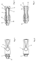
- a fastening element according to the invention is in accordance with Figures 1 to 4 from a trained as a closer Handle 1 and a sleeve 2.
- the sleeve 2 is in Use position in an inner bore 3 of the handle 1 used.
- the handle 1 is according to FIGS. 5 to 8 formed sleeve-shaped and has on its outer surface Recessed grips 4.
- annular collar 11 which leads to the area of the grooves 5 / webs 6 towards an inclined wall 12 and towards the other side wall 13 running approximately perpendicular to the longitudinal axis A. has.
- This wall 13 is also part of an annular groove 14, which is also inserted into the inner bore 3 is. With the perpendicular wall 13 forms again an oblique wall 15 from this annular groove 14.
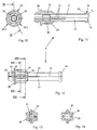
- the sleeve 2 has a shaft 17, at one end of which a collar 18 is provided. At the end, this collar 18 preferably has a spherical shape trained phase 19, at the other end approximately perpendicular to Sleeve axis B extending ring wall 20.
- slots 21 in the sleeve molded, preferably three slots, which in this case form three jaws 22.1, 22.2 and 22.3.
- the slots 21 has each jaw 22.1 to 22.3 from At the end a rising cone 23, followed by it a puncture 24 and then a collar 25.
- An the federal government 25 in turn connects an area consisting of approximately Wedges 26 and grooves running parallel to the sleeve axis B. 27 exists.
- Each wedge has 25 ends at the other end a flat 28 towards the shaft 17, while by a Rising surface 29 between two wedges 26 in the bottom of the groove Cylinder surface 30 is formed with an increased diameter. This can be seen in particular in FIGS. 13 and 14.
- the operation of the present invention is as follows: in a pre-assembly step, the sleeve 2 is in the Handle 1 used, as shown in Figures 1 and 3 is.
- the collar 18 When inserting the collar 18 first meets the sloping wall 12 in the inner bore 3, the Outer phase 19 of the federal government 18 slides on the slope, so that the expanding jaws 10.1 to 10.4 open.
- the wedges 26 engage in the preassembled state the grooves 5 so that the handle can rotate freely compared to the sleeve 2 is no longer possible. Indeed can the jaws 22.1 to 22.3 in the radial direction be moved.
- the jaws are 22.1 to 22.3 free again and can swing radially outwards.
- the thread flanks of the internal thread 32 of the sleeve 2 on the thread flanks of the screw thread of the screw slide.
- the fastener can be without Rotational movement of the screw can be removed.
- the screw penetrates a hole in an object, the hole having a larger diameter than the screw shaft with the external thread.
- the cone 23 engages in the bore when the fastening element is placed on the screw shaft and thus centers the screw and the fastening element.
- compression of the clamping jaws 22.1 to 22.3 is also supported, since the cone 23 moves into the bore until the fastening element with the annular collar 25 lies against the object to be fixed.
- a preload is applied to the object to be fixed via this ring collar 25.
Landscapes
- Engineering & Computer Science (AREA)
- General Engineering & Computer Science (AREA)
- Mechanical Engineering (AREA)
- Health & Medical Sciences (AREA)
- Public Health (AREA)
- Dowels (AREA)
- Connection Of Plates (AREA)
- Clamps And Clips (AREA)
- Motor Or Generator Frames (AREA)
- Fluid-Damping Devices (AREA)
- Rear-View Mirror Devices That Are Mounted On The Exterior Of The Vehicle (AREA)
- Flanged Joints, Insulating Joints, And Other Joints (AREA)
- Finger-Pressure Massage (AREA)
Description
| Positionszahlenliste | |||||
| 1 | Griffstück | 34 | 67 | ||
| 2 | Hülse | 35 | 68 | ||
| 3 | Innenbohrung | 36 | 69 | ||
| 4 | Griffmulde | 37 | 70 | ||
| 5 | Nut | 38 | 71 | ||
| 6 | Stege | 39 | 72 | ||
| 7 | Innenfläche | 40 | 73 | ||
| 8 | Schräge | 41 | 74 | ||
| 9 | Schlitz | 42 | 75 | ||
| 10 | Spreizbacken | 43 | 76 | ||
| 11 | Ringkragen | 44 | 77 | ||
| 12 | Wand | 45 | 78 | ||
| 13 | Wand | 46 | 79 | ||
| 14 | Ringnut | 47 | |||
| 15 | Wand | 48 | A | Längsachse | |
| 16 | Fase | 49 | B | Hülsenachse | |
| 17 | Schaft | 50 | |||
| 18 | Bund | 51 | |||
| 19 | Fase | 52 | |||
| 20 | Ringwand | 53 | |||
| 21 | Schlitz | 54 | |||
| 22 | Spannbacken | 55 | |||
| 23 | Konus | 56 | |||
| 24 | Einstich | 57 | |||
| 25 | Ringbund | 58 | |||
| 26 | Keil | 59 | |||
| 27 | Nut | 60 | |||
| 28 | Abflachung | 61 | |||
| 29 | Steigfläche | 62 | |||
| 30 | Zylinderfläche | 63 | |||
| 31 | Innenbohrung | 64 | |||
| 32 | Innengewinde | 65 | |||
| 33 | 66 |
Claims (16)
- Befestigungselement zum Aufschrauben auf ein Gewinde mit einem Innengewinde (32), wobei der Durchmesser des Innengewindes (32) veränderbar und ein gewünschter Durchmesser festlegbar ist,
dadurch gekennzeichnet, dass das Innengewinde (32) in eine Innenbohrung (31) einer Hülse (2) eingestochen ist und die Hülse (2) einen Schaft (17) aufweist, der mit zumindest einem Längsschlitz (21) versehen ist, wobei auf die Hülse (2) ein axial verschiebbares Griffstück (1) aufgesetzt und darauf axial bewegbar gehalten ist, welches eine Breite des Längsschlitzes (21) und damit den Durchmesser des Innengewindes (32) verringert. - Befestigungselement nach Anspruch 1, dadurch gekennzeichnet, dass auf den Schaft (17) der Hülse (2) zumindest ein teilweise parallel zu dem Längsschlitz (21) und axial verlaufender Keil (26) aufgesetzt ist, der in eine entsprechend geformte Nut (5) in eine Innenfläche (7) des Griffstückes (1) einfährt oder umgekehrt.
- Befestigungselement nach Anspruch 2, dadurch gekennzeichnet, dass in der Nut (5) bzw. zwischen zwei Keilen (26) nach einer Steigfläche (29) eine Zylinderfläche (30) ausgebildet ist.
- Befestigungselement nach Anspruch 2 oder 3, dadurch gekennzeichnet, dass der Keil (26) einerseits nahe einem Ende des Schaftes (17) an einem Ringbund (25) anschliesst und anderenends eine Abflachung (28) zum Schaft (17) hin aufweist.
- Befestigungselement nach einem der Ansprüche 2 bis 4, dadurch gekennzeichnet, dass die Nut (5) im Innern des Griffstückes eine Schräge (8) zur Innenfläche (7) aufweist.
- Befestigungselement nach Anspruch 4 oder 5, dadurch gekennzeichnet, dass an den Ringbund (25) ein Einstich (24) und dadurch ein sich verjüngender Konus (23) anschliesst.
- Befestigungselement nach Anspruch 6, dadurch gekennzeichnet, dass dem Schaft (17) zumindest zwei, besser drei Schlitze (21) eingeformt sind, sodass der jeweilige Konus (23), Einstich (24) sowie die entsprechenden Keile (26) und Schafteile jeweils einen Spannbacken (22.1, 22.2, 22.3) ausbilden.
- Befestigungselement nach Anspruch 7, dadruch gekennzeichnet, dass das Griffstück (1) hülsenförmig ausgebildet ist, mit einer Innenbohrung (3), in welche einends die Nuten (5) zur Aufnahme der Keile (26) eingeformt sind.
- Befestigungselement nach Anspruch 8, dadurch gekennzeichnet, dass das Griffstück (1) nach den Nuten (5) zumindest einen sich zum anderen Ende hin erstreckenden Schlitz (9) aufweist, der in seiner Öffnungsweite veränderbar ist.
- Befestigungselement nach Anspruch 9, dadurch gekennzeichnet, dass dieses andere Ende des Griffstückes (1) eine in die Innenbohrung (3) gerichtete Fase (16) aufweist.
- Befestigungselement nach einem der Ansprüche 8 bis 10, dadurch gekennzeichnet, dass in die Innenbohrung (3) eine Ringnut (14) eingestochen ist.
- Befestigungselement nach Anspruch 11, dadurch gekennzeichnet, dass die dem anderen Ende ferne Wand (13) der Ringnut (14) etwa senkrecht zur Innenbohrung (3) bzw. Achse (A) des Griffstückes (1) ausgebildet ist, während die gegenüberliegende dem anderen Ende nahe Wand (15) schräg in Richtung des anderen Endes hin verläuft.
- Befestigungselement nach Anspruch 11 oder 12, dadurch gekennzeichnet, dass an die senkrecht zur Achse (A) des Griffstückes (1) verlaufende Wand (13) der Ringnut (14) ein Ringkragen (11) anschliesst, dessen andere Wand (12) wiederum in Richtung der Nuten (5) hin abgeschrägt ist.
- Befestigungselement nach wenigstens einem der Ansprüche 9 bis 13, dadurch gekennzeichnet, dass der Hülse (2) ein Bund (18) angeformt ist.
- Befestigungselement nach Anspruch 14, dadurch gekennzeichnet, dass der Bund (18) einerseits eine etwa senkrecht zur Hülsenachse (B) verlaufende Wand (20) und andererseits eine Aussenfase (19) besitzt.
- Befestigungselement nach wenigstens einem der Ansprüche 9 bis 15, dadurch gekennzeichnet, dass das Griffstück (1) mindestens zwei, insbesondere vier Schlitze (9) aufweist.
Applications Claiming Priority (3)
| Application Number | Priority Date | Filing Date | Title |
|---|---|---|---|
| DE10014180A DE10014180A1 (de) | 2000-03-23 | 2000-03-23 | Befestigungselement |
| DE10014180 | 2000-03-23 | ||
| PCT/EP2001/002108 WO2001071203A1 (de) | 2000-03-23 | 2001-02-24 | Befestigungselement |
Publications (2)
| Publication Number | Publication Date |
|---|---|
| EP1269032A1 EP1269032A1 (de) | 2003-01-02 |
| EP1269032B1 true EP1269032B1 (de) | 2004-09-22 |
Family
ID=7635881
Family Applications (1)
| Application Number | Title | Priority Date | Filing Date |
|---|---|---|---|
| EP01907559A Expired - Lifetime EP1269032B1 (de) | 2000-03-23 | 2001-02-24 | Befestigungselement |
Country Status (5)
| Country | Link |
|---|---|
| EP (1) | EP1269032B1 (de) |
| AT (1) | ATE277298T1 (de) |
| AU (1) | AU2001235493A1 (de) |
| DE (2) | DE10014180A1 (de) |
| WO (1) | WO2001071203A1 (de) |
Cited By (1)
| Publication number | Priority date | Publication date | Assignee | Title |
|---|---|---|---|---|
| DE102004026361A1 (de) * | 2004-05-29 | 2005-12-15 | Peter Endres Gmbh & Co. Kg | Toilettenteil mit Schnellspannmutter |
Families Citing this family (1)
| Publication number | Priority date | Publication date | Assignee | Title |
|---|---|---|---|---|
| CN112983958B (zh) * | 2021-03-19 | 2022-04-29 | 南京航空航天大学 | 一种带螺纹套的多开缝衬套直径可变装置及其使用方法 |
Family Cites Families (4)
| Publication number | Priority date | Publication date | Assignee | Title |
|---|---|---|---|---|
| US3739684A (en) * | 1971-11-12 | 1973-06-19 | J Vitkevich | Expansion hanger device |
| FR2353746A1 (fr) * | 1976-05-31 | 1977-12-30 | Allibert Exploitation | Systeme pour la fixation d'organes quelconques, tel qu'un abattant sur une cuvette de w.c. |
| DE3927529C1 (de) * | 1989-08-21 | 1991-03-07 | A. Raymond Kg, 7850 Loerrach, De | |
| KR100496945B1 (ko) * | 1996-09-25 | 2005-09-30 | 에요트 페르빈둥스테크닉크 게엠베하 운트 콤파니 카게 | 패널형부품연결용플라스틱너트 |
-
2000
- 2000-03-23 DE DE10014180A patent/DE10014180A1/de not_active Withdrawn
-
2001
- 2001-02-24 WO PCT/EP2001/002108 patent/WO2001071203A1/de not_active Ceased
- 2001-02-24 AT AT01907559T patent/ATE277298T1/de not_active IP Right Cessation
- 2001-02-24 AU AU2001235493A patent/AU2001235493A1/en not_active Abandoned
- 2001-02-24 EP EP01907559A patent/EP1269032B1/de not_active Expired - Lifetime
- 2001-02-24 DE DE50103763T patent/DE50103763D1/de not_active Expired - Fee Related
Cited By (1)
| Publication number | Priority date | Publication date | Assignee | Title |
|---|---|---|---|---|
| DE102004026361A1 (de) * | 2004-05-29 | 2005-12-15 | Peter Endres Gmbh & Co. Kg | Toilettenteil mit Schnellspannmutter |
Also Published As
| Publication number | Publication date |
|---|---|
| AU2001235493A1 (en) | 2001-10-03 |
| EP1269032A1 (de) | 2003-01-02 |
| DE50103763D1 (de) | 2004-10-28 |
| WO2001071203A1 (de) | 2001-09-27 |
| ATE277298T1 (de) | 2004-10-15 |
| DE10014180A1 (de) | 2001-09-27 |
Similar Documents
| Publication | Publication Date | Title |
|---|---|---|
| EP1510701B1 (de) | Vorrichtung zum Verbinden von Bauteilen mit Blindnietbefestigung | |
| DE10126747C2 (de) | Blindnietmutter und Befestigungseinheit | |
| DE19505311C2 (de) | Befestigungsanordnung von Beschlägen, insbesondere Möbelbeschlägen an Möbelstücken | |
| DE19749219B4 (de) | Nicht-wiederabnehmbare Befestigungsvorrichtung | |
| EP1918596B1 (de) | Blindnietelement sowie Verwendung hierfür | |
| DE602004002611T2 (de) | Wanddübel für eine Schraube und die Anordnung, die durch solch einen Wanddübel und eine Schraube festgesetzt wird. | |
| WO1994007040A1 (de) | Vorrichtung zum verbinden von wenigstens zwei elementen | |
| DE10261748A1 (de) | Stanzwerkzeug | |
| DE1475014A1 (de) | Befestigungsteil | |
| DE1400889B2 (de) | Dübel und Verfahren zum Einbau desselben in eine Bohrung einer Schichtverbundplatte | |
| DE2610200A1 (de) | Beschlag zum loesbaren verbinden von bauteilen, insbesondere zum wieder loesbaren verbinden von plattenfoermigen bauteilen | |
| EP0942806A1 (de) | Nuss zur aufnahme eines oder zum einsetzen in einen befestigerkopf(es) | |
| DE1500848A1 (de) | Verbindungselement fuer die Montage von Moebelteilen,insbesondere fuer die Verbindung von Beinen mit dem Rahmen eines Moebels | |
| DD299202A5 (de) | Vorrichtung zur befestigung eines insbesondere rohrfoermigen bauteils an einer wand oder dgl. | |
| DE1085721B (de) | Klemmverbindung | |
| DE19723425A1 (de) | Spannbolzen | |
| DE2909749A1 (de) | Duebel und werkzeug zum befestigen des duebels | |
| DE1500893B1 (de) | Verankerungsduebel fuer Leichtbau-Schichtverbundplatten | |
| DE19652318C1 (de) | Schraube zur gegenseitigen Befestigung von wenigstens zwei Bauteilen | |
| EP3599385B1 (de) | Kugelsperrbolzen mit kopfnaher arretierung | |
| EP0864767B1 (de) | Verbindungsmuffe und Vorrichtung zur Befestigung von Gegenständen an Wänden oder dgl. | |
| DE19531016C2 (de) | Verbindungselement, nach Art eines Niets | |
| DE10014180A1 (de) | Befestigungselement | |
| DE10245235B4 (de) | Spannsatz | |
| DE20302306U1 (de) | Verbindungselement für den Möbelbau und Verbindungsanordnung |
Legal Events
| Date | Code | Title | Description |
|---|---|---|---|
| PUAI | Public reference made under article 153(3) epc to a published international application that has entered the european phase |
Free format text: ORIGINAL CODE: 0009012 |
|
| 17P | Request for examination filed |
Effective date: 20020905 |
|
| AK | Designated contracting states |
Kind code of ref document: A1 Designated state(s): AT BE CH CY DE DK ES FI FR GB GR IE IT LI LU MC NL PT SE TR |
|
| AX | Request for extension of the european patent |
Free format text: AL;LT;LV;MK;RO;SI |
|
| 17Q | First examination report despatched |
Effective date: 20030618 |
|
| GRAP | Despatch of communication of intention to grant a patent |
Free format text: ORIGINAL CODE: EPIDOSNIGR1 |
|
| GRAS | Grant fee paid |
Free format text: ORIGINAL CODE: EPIDOSNIGR3 |
|
| GRAA | (expected) grant |
Free format text: ORIGINAL CODE: 0009210 |
|
| AK | Designated contracting states |
Kind code of ref document: B1 Designated state(s): AT BE CH CY DE DK ES FI FR GB GR IE IT LI LU MC NL PT SE TR |
|
| PG25 | Lapsed in a contracting state [announced via postgrant information from national office to epo] |
Ref country code: FI Free format text: LAPSE BECAUSE OF FAILURE TO SUBMIT A TRANSLATION OF THE DESCRIPTION OR TO PAY THE FEE WITHIN THE PRESCRIBED TIME-LIMIT Effective date: 20040922 Ref country code: IE Free format text: LAPSE BECAUSE OF FAILURE TO SUBMIT A TRANSLATION OF THE DESCRIPTION OR TO PAY THE FEE WITHIN THE PRESCRIBED TIME-LIMIT Effective date: 20040922 Ref country code: FR Free format text: LAPSE BECAUSE OF FAILURE TO SUBMIT A TRANSLATION OF THE DESCRIPTION OR TO PAY THE FEE WITHIN THE PRESCRIBED TIME-LIMIT Effective date: 20040922 Ref country code: ES Free format text: LAPSE BECAUSE OF FAILURE TO SUBMIT A TRANSLATION OF THE DESCRIPTION OR TO PAY THE FEE WITHIN THE PRESCRIBED TIME-LIMIT Effective date: 20040922 Ref country code: TR Free format text: LAPSE BECAUSE OF FAILURE TO SUBMIT A TRANSLATION OF THE DESCRIPTION OR TO PAY THE FEE WITHIN THE PRESCRIBED TIME-LIMIT Effective date: 20040922 Ref country code: NL Free format text: LAPSE BECAUSE OF FAILURE TO SUBMIT A TRANSLATION OF THE DESCRIPTION OR TO PAY THE FEE WITHIN THE PRESCRIBED TIME-LIMIT Effective date: 20040922 Ref country code: IT Free format text: LAPSE BECAUSE OF FAILURE TO SUBMIT A TRANSLATION OF THE DESCRIPTION OR TO PAY THE FEE WITHIN THE PRESCRIBED TIME-LIMIT;WARNING: LAPSES OF ITALIAN PATENTS WITH EFFECTIVE DATE BEFORE 2007 MAY HAVE OCCURRED AT ANY TIME BEFORE 2007. THE CORRECT EFFECTIVE DATE MAY BE DIFFERENT FROM THE ONE RECORDED. Effective date: 20040922 |
|
| REG | Reference to a national code |
Ref country code: GB Ref legal event code: FG4D Free format text: NOT ENGLISH |
|
| REG | Reference to a national code |
Ref country code: CH Ref legal event code: EP |
|
| REG | Reference to a national code |
Ref country code: IE Ref legal event code: FG4D Free format text: GERMAN |
|
| REF | Corresponds to: |
Ref document number: 50103763 Country of ref document: DE Date of ref document: 20041028 Kind code of ref document: P |
|
| PG25 | Lapsed in a contracting state [announced via postgrant information from national office to epo] |
Ref country code: GR Free format text: LAPSE BECAUSE OF FAILURE TO SUBMIT A TRANSLATION OF THE DESCRIPTION OR TO PAY THE FEE WITHIN THE PRESCRIBED TIME-LIMIT Effective date: 20041222 Ref country code: DK Free format text: LAPSE BECAUSE OF FAILURE TO SUBMIT A TRANSLATION OF THE DESCRIPTION OR TO PAY THE FEE WITHIN THE PRESCRIBED TIME-LIMIT Effective date: 20041222 |
|
| REG | Reference to a national code |
Ref country code: SE Ref legal event code: TRGR |
|
| GBT | Gb: translation of ep patent filed (gb section 77(6)(a)/1977) |
Effective date: 20050117 |
|
| PG25 | Lapsed in a contracting state [announced via postgrant information from national office to epo] |
Ref country code: LU Free format text: LAPSE BECAUSE OF NON-PAYMENT OF DUE FEES Effective date: 20050224 Ref country code: AT Free format text: LAPSE BECAUSE OF NON-PAYMENT OF DUE FEES Effective date: 20050224 Ref country code: CY Free format text: LAPSE BECAUSE OF FAILURE TO SUBMIT A TRANSLATION OF THE DESCRIPTION OR TO PAY THE FEE WITHIN THE PRESCRIBED TIME-LIMIT Effective date: 20050224 |
|
| LTIE | Lt: invalidation of european patent or patent extension |
Effective date: 20040922 |
|
| PG25 | Lapsed in a contracting state [announced via postgrant information from national office to epo] |
Ref country code: BE Free format text: LAPSE BECAUSE OF NON-PAYMENT OF DUE FEES Effective date: 20050228 Ref country code: MC Free format text: LAPSE BECAUSE OF NON-PAYMENT OF DUE FEES Effective date: 20050228 Ref country code: LI Free format text: LAPSE BECAUSE OF NON-PAYMENT OF DUE FEES Effective date: 20050228 Ref country code: CH Free format text: LAPSE BECAUSE OF NON-PAYMENT OF DUE FEES Effective date: 20050228 |
|
| NLV1 | Nl: lapsed or annulled due to failure to fulfill the requirements of art. 29p and 29m of the patents act | ||
| REG | Reference to a national code |
Ref country code: IE Ref legal event code: FD4D |
|
| PLBE | No opposition filed within time limit |
Free format text: ORIGINAL CODE: 0009261 |
|
| STAA | Information on the status of an ep patent application or granted ep patent |
Free format text: STATUS: NO OPPOSITION FILED WITHIN TIME LIMIT |
|
| BERE | Be: lapsed |
Owner name: EUREHA G.M.B.H. Effective date: 20050228 |
|
| 26N | No opposition filed |
Effective date: 20050623 |
|
| EN | Fr: translation not filed | ||
| REG | Reference to a national code |
Ref country code: CH Ref legal event code: PL |
|
| BERE | Be: lapsed |
Owner name: *EUREHA G.M.B.H. Effective date: 20050228 |
|
| PG25 | Lapsed in a contracting state [announced via postgrant information from national office to epo] |
Ref country code: PT Free format text: LAPSE BECAUSE OF NON-PAYMENT OF DUE FEES Effective date: 20050222 |
|
| PGFP | Annual fee paid to national office [announced via postgrant information from national office to epo] |
Ref country code: GB Payment date: 20090227 Year of fee payment: 9 |
|
| PGFP | Annual fee paid to national office [announced via postgrant information from national office to epo] |
Ref country code: DE Payment date: 20090428 Year of fee payment: 9 Ref country code: SE Payment date: 20090226 Year of fee payment: 9 |
|
| EUG | Se: european patent has lapsed | ||
| GBPC | Gb: european patent ceased through non-payment of renewal fee |
Effective date: 20100224 |
|
| PG25 | Lapsed in a contracting state [announced via postgrant information from national office to epo] |
Ref country code: DE Free format text: LAPSE BECAUSE OF NON-PAYMENT OF DUE FEES Effective date: 20100901 |
|
| PG25 | Lapsed in a contracting state [announced via postgrant information from national office to epo] |
Ref country code: GB Free format text: LAPSE BECAUSE OF NON-PAYMENT OF DUE FEES Effective date: 20100224 |
|
| PG25 | Lapsed in a contracting state [announced via postgrant information from national office to epo] |
Ref country code: SE Free format text: LAPSE BECAUSE OF NON-PAYMENT OF DUE FEES Effective date: 20100225 |