EP1267432A2 - Fuel cell refueling station and system - Google Patents
Fuel cell refueling station and system Download PDFInfo
- Publication number
- EP1267432A2 EP1267432A2 EP02254177A EP02254177A EP1267432A2 EP 1267432 A2 EP1267432 A2 EP 1267432A2 EP 02254177 A EP02254177 A EP 02254177A EP 02254177 A EP02254177 A EP 02254177A EP 1267432 A2 EP1267432 A2 EP 1267432A2
- Authority
- EP
- European Patent Office
- Prior art keywords
- hydrogen
- heat exchanger
- natural gas
- reformer
- liquid natural
- Prior art date
- Legal status (The legal status is an assumption and is not a legal conclusion. Google has not performed a legal analysis and makes no representation as to the accuracy of the status listed.)
- Ceased
Links
Images


Classifications
-
- H—ELECTRICITY
- H01—ELECTRIC ELEMENTS
- H01M—PROCESSES OR MEANS, e.g. BATTERIES, FOR THE DIRECT CONVERSION OF CHEMICAL ENERGY INTO ELECTRICAL ENERGY
- H01M8/00—Fuel cells; Manufacture thereof
- H01M8/06—Combination of fuel cells with means for production of reactants or for treatment of residues
- H01M8/0606—Combination of fuel cells with means for production of reactants or for treatment of residues with means for production of gaseous reactants
- H01M8/0612—Combination of fuel cells with means for production of reactants or for treatment of residues with means for production of gaseous reactants from carbon-containing material
-
- B—PERFORMING OPERATIONS; TRANSPORTING
- B60—VEHICLES IN GENERAL
- B60L—PROPULSION OF ELECTRICALLY-PROPELLED VEHICLES; SUPPLYING ELECTRIC POWER FOR AUXILIARY EQUIPMENT OF ELECTRICALLY-PROPELLED VEHICLES; ELECTRODYNAMIC BRAKE SYSTEMS FOR VEHICLES IN GENERAL; MAGNETIC SUSPENSION OR LEVITATION FOR VEHICLES; MONITORING OPERATING VARIABLES OF ELECTRICALLY-PROPELLED VEHICLES; ELECTRIC SAFETY DEVICES FOR ELECTRICALLY-PROPELLED VEHICLES
- B60L58/00—Methods or circuit arrangements for monitoring or controlling batteries or fuel cells, specially adapted for electric vehicles
- B60L58/30—Methods or circuit arrangements for monitoring or controlling batteries or fuel cells, specially adapted for electric vehicles for monitoring or controlling fuel cells
- B60L58/32—Methods or circuit arrangements for monitoring or controlling batteries or fuel cells, specially adapted for electric vehicles for monitoring or controlling fuel cells for controlling the temperature of fuel cells, e.g. by controlling the electric load
- B60L58/33—Methods or circuit arrangements for monitoring or controlling batteries or fuel cells, specially adapted for electric vehicles for monitoring or controlling fuel cells for controlling the temperature of fuel cells, e.g. by controlling the electric load by cooling
-
- B—PERFORMING OPERATIONS; TRANSPORTING
- B60—VEHICLES IN GENERAL
- B60L—PROPULSION OF ELECTRICALLY-PROPELLED VEHICLES; SUPPLYING ELECTRIC POWER FOR AUXILIARY EQUIPMENT OF ELECTRICALLY-PROPELLED VEHICLES; ELECTRODYNAMIC BRAKE SYSTEMS FOR VEHICLES IN GENERAL; MAGNETIC SUSPENSION OR LEVITATION FOR VEHICLES; MONITORING OPERATING VARIABLES OF ELECTRICALLY-PROPELLED VEHICLES; ELECTRIC SAFETY DEVICES FOR ELECTRICALLY-PROPELLED VEHICLES
- B60L58/00—Methods or circuit arrangements for monitoring or controlling batteries or fuel cells, specially adapted for electric vehicles
- B60L58/30—Methods or circuit arrangements for monitoring or controlling batteries or fuel cells, specially adapted for electric vehicles for monitoring or controlling fuel cells
- B60L58/32—Methods or circuit arrangements for monitoring or controlling batteries or fuel cells, specially adapted for electric vehicles for monitoring or controlling fuel cells for controlling the temperature of fuel cells, e.g. by controlling the electric load
- B60L58/34—Methods or circuit arrangements for monitoring or controlling batteries or fuel cells, specially adapted for electric vehicles for monitoring or controlling fuel cells for controlling the temperature of fuel cells, e.g. by controlling the electric load by heating
-
- C—CHEMISTRY; METALLURGY
- C01—INORGANIC CHEMISTRY
- C01B—NON-METALLIC ELEMENTS; COMPOUNDS THEREOF; METALLOIDS OR COMPOUNDS THEREOF NOT COVERED BY SUBCLASS C01C
- C01B3/00—Hydrogen; Gaseous mixtures containing hydrogen; Separation of hydrogen from mixtures containing it; Purification of hydrogen
- C01B3/02—Production of hydrogen or of gaseous mixtures containing a substantial proportion of hydrogen
- C01B3/32—Production of hydrogen or of gaseous mixtures containing a substantial proportion of hydrogen by reaction of gaseous or liquid organic compounds with gasifying agents, e.g. water, carbon dioxide, air
- C01B3/34—Production of hydrogen or of gaseous mixtures containing a substantial proportion of hydrogen by reaction of gaseous or liquid organic compounds with gasifying agents, e.g. water, carbon dioxide, air by reaction of hydrocarbons with gasifying agents
-
- F—MECHANICAL ENGINEERING; LIGHTING; HEATING; WEAPONS; BLASTING
- F17—STORING OR DISTRIBUTING GASES OR LIQUIDS
- F17C—VESSELS FOR CONTAINING OR STORING COMPRESSED, LIQUEFIED OR SOLIDIFIED GASES; FIXED-CAPACITY GAS-HOLDERS; FILLING VESSELS WITH, OR DISCHARGING FROM VESSELS, COMPRESSED, LIQUEFIED, OR SOLIDIFIED GASES
- F17C5/00—Methods or apparatus for filling containers with liquefied, solidified, or compressed gases under pressures
- F17C5/002—Automated filling apparatus
- F17C5/007—Automated filling apparatus for individual gas tanks or containers, e.g. in vehicles
-
- F—MECHANICAL ENGINEERING; LIGHTING; HEATING; WEAPONS; BLASTING
- F17—STORING OR DISTRIBUTING GASES OR LIQUIDS
- F17C—VESSELS FOR CONTAINING OR STORING COMPRESSED, LIQUEFIED OR SOLIDIFIED GASES; FIXED-CAPACITY GAS-HOLDERS; FILLING VESSELS WITH, OR DISCHARGING FROM VESSELS, COMPRESSED, LIQUEFIED, OR SOLIDIFIED GASES
- F17C5/00—Methods or apparatus for filling containers with liquefied, solidified, or compressed gases under pressures
- F17C5/02—Methods or apparatus for filling containers with liquefied, solidified, or compressed gases under pressures for filling with liquefied gases
- F17C5/04—Methods or apparatus for filling containers with liquefied, solidified, or compressed gases under pressures for filling with liquefied gases requiring the use of refrigeration, e.g. filling with helium or hydrogen
-
- F—MECHANICAL ENGINEERING; LIGHTING; HEATING; WEAPONS; BLASTING
- F17—STORING OR DISTRIBUTING GASES OR LIQUIDS
- F17C—VESSELS FOR CONTAINING OR STORING COMPRESSED, LIQUEFIED OR SOLIDIFIED GASES; FIXED-CAPACITY GAS-HOLDERS; FILLING VESSELS WITH, OR DISCHARGING FROM VESSELS, COMPRESSED, LIQUEFIED, OR SOLIDIFIED GASES
- F17C5/00—Methods or apparatus for filling containers with liquefied, solidified, or compressed gases under pressures
- F17C5/06—Methods or apparatus for filling containers with liquefied, solidified, or compressed gases under pressures for filling with compressed gases
-
- F—MECHANICAL ENGINEERING; LIGHTING; HEATING; WEAPONS; BLASTING
- F17—STORING OR DISTRIBUTING GASES OR LIQUIDS
- F17C—VESSELS FOR CONTAINING OR STORING COMPRESSED, LIQUEFIED OR SOLIDIFIED GASES; FIXED-CAPACITY GAS-HOLDERS; FILLING VESSELS WITH, OR DISCHARGING FROM VESSELS, COMPRESSED, LIQUEFIED, OR SOLIDIFIED GASES
- F17C9/00—Methods or apparatus for discharging liquefied or solidified gases from vessels not under pressure
- F17C9/02—Methods or apparatus for discharging liquefied or solidified gases from vessels not under pressure with change of state, e.g. vaporisation
-
- C—CHEMISTRY; METALLURGY
- C01—INORGANIC CHEMISTRY
- C01B—NON-METALLIC ELEMENTS; COMPOUNDS THEREOF; METALLOIDS OR COMPOUNDS THEREOF NOT COVERED BY SUBCLASS C01C
- C01B2203/00—Integrated processes for the production of hydrogen or synthesis gas
- C01B2203/02—Processes for making hydrogen or synthesis gas
- C01B2203/0205—Processes for making hydrogen or synthesis gas containing a reforming step
- C01B2203/0227—Processes for making hydrogen or synthesis gas containing a reforming step containing a catalytic reforming step
-
- C—CHEMISTRY; METALLURGY
- C01—INORGANIC CHEMISTRY
- C01B—NON-METALLIC ELEMENTS; COMPOUNDS THEREOF; METALLOIDS OR COMPOUNDS THEREOF NOT COVERED BY SUBCLASS C01C
- C01B2203/00—Integrated processes for the production of hydrogen or synthesis gas
- C01B2203/04—Integrated processes for the production of hydrogen or synthesis gas containing a purification step for the hydrogen or the synthesis gas
- C01B2203/0465—Composition of the impurity
- C01B2203/0475—Composition of the impurity the impurity being carbon dioxide
-
- C—CHEMISTRY; METALLURGY
- C01—INORGANIC CHEMISTRY
- C01B—NON-METALLIC ELEMENTS; COMPOUNDS THEREOF; METALLOIDS OR COMPOUNDS THEREOF NOT COVERED BY SUBCLASS C01C
- C01B2203/00—Integrated processes for the production of hydrogen or synthesis gas
- C01B2203/06—Integration with other chemical processes
- C01B2203/066—Integration with other chemical processes with fuel cells
-
- C—CHEMISTRY; METALLURGY
- C01—INORGANIC CHEMISTRY
- C01B—NON-METALLIC ELEMENTS; COMPOUNDS THEREOF; METALLOIDS OR COMPOUNDS THEREOF NOT COVERED BY SUBCLASS C01C
- C01B2203/00—Integrated processes for the production of hydrogen or synthesis gas
- C01B2203/12—Feeding the process for making hydrogen or synthesis gas
- C01B2203/1205—Composition of the feed
- C01B2203/1211—Organic compounds or organic mixtures used in the process for making hydrogen or synthesis gas
- C01B2203/1235—Hydrocarbons
- C01B2203/1241—Natural gas or methane
-
- F—MECHANICAL ENGINEERING; LIGHTING; HEATING; WEAPONS; BLASTING
- F17—STORING OR DISTRIBUTING GASES OR LIQUIDS
- F17C—VESSELS FOR CONTAINING OR STORING COMPRESSED, LIQUEFIED OR SOLIDIFIED GASES; FIXED-CAPACITY GAS-HOLDERS; FILLING VESSELS WITH, OR DISCHARGING FROM VESSELS, COMPRESSED, LIQUEFIED, OR SOLIDIFIED GASES
- F17C2201/00—Vessel construction, in particular geometry, arrangement or size
- F17C2201/01—Shape
- F17C2201/0104—Shape cylindrical
-
- F—MECHANICAL ENGINEERING; LIGHTING; HEATING; WEAPONS; BLASTING
- F17—STORING OR DISTRIBUTING GASES OR LIQUIDS
- F17C—VESSELS FOR CONTAINING OR STORING COMPRESSED, LIQUEFIED OR SOLIDIFIED GASES; FIXED-CAPACITY GAS-HOLDERS; FILLING VESSELS WITH, OR DISCHARGING FROM VESSELS, COMPRESSED, LIQUEFIED, OR SOLIDIFIED GASES
- F17C2201/00—Vessel construction, in particular geometry, arrangement or size
- F17C2201/05—Size
- F17C2201/052—Size large (>1000 m3)
-
- F—MECHANICAL ENGINEERING; LIGHTING; HEATING; WEAPONS; BLASTING
- F17—STORING OR DISTRIBUTING GASES OR LIQUIDS
- F17C—VESSELS FOR CONTAINING OR STORING COMPRESSED, LIQUEFIED OR SOLIDIFIED GASES; FIXED-CAPACITY GAS-HOLDERS; FILLING VESSELS WITH, OR DISCHARGING FROM VESSELS, COMPRESSED, LIQUEFIED, OR SOLIDIFIED GASES
- F17C2201/00—Vessel construction, in particular geometry, arrangement or size
- F17C2201/05—Size
- F17C2201/054—Size medium (>1 m3)
-
- F—MECHANICAL ENGINEERING; LIGHTING; HEATING; WEAPONS; BLASTING
- F17—STORING OR DISTRIBUTING GASES OR LIQUIDS
- F17C—VESSELS FOR CONTAINING OR STORING COMPRESSED, LIQUEFIED OR SOLIDIFIED GASES; FIXED-CAPACITY GAS-HOLDERS; FILLING VESSELS WITH, OR DISCHARGING FROM VESSELS, COMPRESSED, LIQUEFIED, OR SOLIDIFIED GASES
- F17C2221/00—Handled fluid, in particular type of fluid
- F17C2221/01—Pure fluids
- F17C2221/012—Hydrogen
-
- F—MECHANICAL ENGINEERING; LIGHTING; HEATING; WEAPONS; BLASTING
- F17—STORING OR DISTRIBUTING GASES OR LIQUIDS
- F17C—VESSELS FOR CONTAINING OR STORING COMPRESSED, LIQUEFIED OR SOLIDIFIED GASES; FIXED-CAPACITY GAS-HOLDERS; FILLING VESSELS WITH, OR DISCHARGING FROM VESSELS, COMPRESSED, LIQUEFIED, OR SOLIDIFIED GASES
- F17C2221/00—Handled fluid, in particular type of fluid
- F17C2221/01—Pure fluids
- F17C2221/013—Carbone dioxide
-
- F—MECHANICAL ENGINEERING; LIGHTING; HEATING; WEAPONS; BLASTING
- F17—STORING OR DISTRIBUTING GASES OR LIQUIDS
- F17C—VESSELS FOR CONTAINING OR STORING COMPRESSED, LIQUEFIED OR SOLIDIFIED GASES; FIXED-CAPACITY GAS-HOLDERS; FILLING VESSELS WITH, OR DISCHARGING FROM VESSELS, COMPRESSED, LIQUEFIED, OR SOLIDIFIED GASES
- F17C2221/00—Handled fluid, in particular type of fluid
- F17C2221/03—Mixtures
- F17C2221/032—Hydrocarbons
- F17C2221/033—Methane, e.g. natural gas, CNG, LNG, GNL, GNC, PLNG
-
- F—MECHANICAL ENGINEERING; LIGHTING; HEATING; WEAPONS; BLASTING
- F17—STORING OR DISTRIBUTING GASES OR LIQUIDS
- F17C—VESSELS FOR CONTAINING OR STORING COMPRESSED, LIQUEFIED OR SOLIDIFIED GASES; FIXED-CAPACITY GAS-HOLDERS; FILLING VESSELS WITH, OR DISCHARGING FROM VESSELS, COMPRESSED, LIQUEFIED, OR SOLIDIFIED GASES
- F17C2223/00—Handled fluid before transfer, i.e. state of fluid when stored in the vessel or before transfer from the vessel
- F17C2223/01—Handled fluid before transfer, i.e. state of fluid when stored in the vessel or before transfer from the vessel characterised by the phase
- F17C2223/0146—Two-phase
- F17C2223/0153—Liquefied gas, e.g. LPG, GPL
- F17C2223/0161—Liquefied gas, e.g. LPG, GPL cryogenic, e.g. LNG, GNL, PLNG
-
- F—MECHANICAL ENGINEERING; LIGHTING; HEATING; WEAPONS; BLASTING
- F17—STORING OR DISTRIBUTING GASES OR LIQUIDS
- F17C—VESSELS FOR CONTAINING OR STORING COMPRESSED, LIQUEFIED OR SOLIDIFIED GASES; FIXED-CAPACITY GAS-HOLDERS; FILLING VESSELS WITH, OR DISCHARGING FROM VESSELS, COMPRESSED, LIQUEFIED, OR SOLIDIFIED GASES
- F17C2223/00—Handled fluid before transfer, i.e. state of fluid when stored in the vessel or before transfer from the vessel
- F17C2223/04—Handled fluid before transfer, i.e. state of fluid when stored in the vessel or before transfer from the vessel characterised by other properties of handled fluid before transfer
- F17C2223/042—Localisation of the removal point
- F17C2223/046—Localisation of the removal point in the liquid
-
- F—MECHANICAL ENGINEERING; LIGHTING; HEATING; WEAPONS; BLASTING
- F17—STORING OR DISTRIBUTING GASES OR LIQUIDS
- F17C—VESSELS FOR CONTAINING OR STORING COMPRESSED, LIQUEFIED OR SOLIDIFIED GASES; FIXED-CAPACITY GAS-HOLDERS; FILLING VESSELS WITH, OR DISCHARGING FROM VESSELS, COMPRESSED, LIQUEFIED, OR SOLIDIFIED GASES
- F17C2225/00—Handled fluid after transfer, i.e. state of fluid after transfer from the vessel
- F17C2225/01—Handled fluid after transfer, i.e. state of fluid after transfer from the vessel characterised by the phase
- F17C2225/0107—Single phase
- F17C2225/0123—Single phase gaseous, e.g. CNG, GNC
-
- F—MECHANICAL ENGINEERING; LIGHTING; HEATING; WEAPONS; BLASTING
- F17—STORING OR DISTRIBUTING GASES OR LIQUIDS
- F17C—VESSELS FOR CONTAINING OR STORING COMPRESSED, LIQUEFIED OR SOLIDIFIED GASES; FIXED-CAPACITY GAS-HOLDERS; FILLING VESSELS WITH, OR DISCHARGING FROM VESSELS, COMPRESSED, LIQUEFIED, OR SOLIDIFIED GASES
- F17C2225/00—Handled fluid after transfer, i.e. state of fluid after transfer from the vessel
- F17C2225/01—Handled fluid after transfer, i.e. state of fluid after transfer from the vessel characterised by the phase
- F17C2225/0107—Single phase
- F17C2225/013—Single phase liquid
-
- F—MECHANICAL ENGINEERING; LIGHTING; HEATING; WEAPONS; BLASTING
- F17—STORING OR DISTRIBUTING GASES OR LIQUIDS
- F17C—VESSELS FOR CONTAINING OR STORING COMPRESSED, LIQUEFIED OR SOLIDIFIED GASES; FIXED-CAPACITY GAS-HOLDERS; FILLING VESSELS WITH, OR DISCHARGING FROM VESSELS, COMPRESSED, LIQUEFIED, OR SOLIDIFIED GASES
- F17C2225/00—Handled fluid after transfer, i.e. state of fluid after transfer from the vessel
- F17C2225/01—Handled fluid after transfer, i.e. state of fluid after transfer from the vessel characterised by the phase
- F17C2225/0146—Two-phase
- F17C2225/0153—Liquefied gas, e.g. LPG, GPL
- F17C2225/0161—Liquefied gas, e.g. LPG, GPL cryogenic, e.g. LNG, GNL, PLNG
-
- F—MECHANICAL ENGINEERING; LIGHTING; HEATING; WEAPONS; BLASTING
- F17—STORING OR DISTRIBUTING GASES OR LIQUIDS
- F17C—VESSELS FOR CONTAINING OR STORING COMPRESSED, LIQUEFIED OR SOLIDIFIED GASES; FIXED-CAPACITY GAS-HOLDERS; FILLING VESSELS WITH, OR DISCHARGING FROM VESSELS, COMPRESSED, LIQUEFIED, OR SOLIDIFIED GASES
- F17C2225/00—Handled fluid after transfer, i.e. state of fluid after transfer from the vessel
- F17C2225/03—Handled fluid after transfer, i.e. state of fluid after transfer from the vessel characterised by the pressure level
- F17C2225/033—Small pressure, e.g. for liquefied gas
-
- F—MECHANICAL ENGINEERING; LIGHTING; HEATING; WEAPONS; BLASTING
- F17—STORING OR DISTRIBUTING GASES OR LIQUIDS
- F17C—VESSELS FOR CONTAINING OR STORING COMPRESSED, LIQUEFIED OR SOLIDIFIED GASES; FIXED-CAPACITY GAS-HOLDERS; FILLING VESSELS WITH, OR DISCHARGING FROM VESSELS, COMPRESSED, LIQUEFIED, OR SOLIDIFIED GASES
- F17C2225/00—Handled fluid after transfer, i.e. state of fluid after transfer from the vessel
- F17C2225/03—Handled fluid after transfer, i.e. state of fluid after transfer from the vessel characterised by the pressure level
- F17C2225/035—High pressure, i.e. between 10 and 80 bars
-
- F—MECHANICAL ENGINEERING; LIGHTING; HEATING; WEAPONS; BLASTING
- F17—STORING OR DISTRIBUTING GASES OR LIQUIDS
- F17C—VESSELS FOR CONTAINING OR STORING COMPRESSED, LIQUEFIED OR SOLIDIFIED GASES; FIXED-CAPACITY GAS-HOLDERS; FILLING VESSELS WITH, OR DISCHARGING FROM VESSELS, COMPRESSED, LIQUEFIED, OR SOLIDIFIED GASES
- F17C2225/00—Handled fluid after transfer, i.e. state of fluid after transfer from the vessel
- F17C2225/03—Handled fluid after transfer, i.e. state of fluid after transfer from the vessel characterised by the pressure level
- F17C2225/036—Very high pressure, i.e. above 80 bars
-
- F—MECHANICAL ENGINEERING; LIGHTING; HEATING; WEAPONS; BLASTING
- F17—STORING OR DISTRIBUTING GASES OR LIQUIDS
- F17C—VESSELS FOR CONTAINING OR STORING COMPRESSED, LIQUEFIED OR SOLIDIFIED GASES; FIXED-CAPACITY GAS-HOLDERS; FILLING VESSELS WITH, OR DISCHARGING FROM VESSELS, COMPRESSED, LIQUEFIED, OR SOLIDIFIED GASES
- F17C2227/00—Transfer of fluids, i.e. method or means for transferring the fluid; Heat exchange with the fluid
- F17C2227/01—Propulsion of the fluid
- F17C2227/0128—Propulsion of the fluid with pumps or compressors
- F17C2227/0135—Pumps
-
- F—MECHANICAL ENGINEERING; LIGHTING; HEATING; WEAPONS; BLASTING
- F17—STORING OR DISTRIBUTING GASES OR LIQUIDS
- F17C—VESSELS FOR CONTAINING OR STORING COMPRESSED, LIQUEFIED OR SOLIDIFIED GASES; FIXED-CAPACITY GAS-HOLDERS; FILLING VESSELS WITH, OR DISCHARGING FROM VESSELS, COMPRESSED, LIQUEFIED, OR SOLIDIFIED GASES
- F17C2227/00—Transfer of fluids, i.e. method or means for transferring the fluid; Heat exchange with the fluid
- F17C2227/01—Propulsion of the fluid
- F17C2227/0128—Propulsion of the fluid with pumps or compressors
- F17C2227/0157—Compressors
- F17C2227/0164—Compressors with specified compressor type, e.g. piston or impulsive type
-
- F—MECHANICAL ENGINEERING; LIGHTING; HEATING; WEAPONS; BLASTING
- F17—STORING OR DISTRIBUTING GASES OR LIQUIDS
- F17C—VESSELS FOR CONTAINING OR STORING COMPRESSED, LIQUEFIED OR SOLIDIFIED GASES; FIXED-CAPACITY GAS-HOLDERS; FILLING VESSELS WITH, OR DISCHARGING FROM VESSELS, COMPRESSED, LIQUEFIED, OR SOLIDIFIED GASES
- F17C2227/00—Transfer of fluids, i.e. method or means for transferring the fluid; Heat exchange with the fluid
- F17C2227/03—Heat exchange with the fluid
- F17C2227/0302—Heat exchange with the fluid by heating
- F17C2227/0309—Heat exchange with the fluid by heating using another fluid
- F17C2227/0311—Air heating
-
- F—MECHANICAL ENGINEERING; LIGHTING; HEATING; WEAPONS; BLASTING
- F17—STORING OR DISTRIBUTING GASES OR LIQUIDS
- F17C—VESSELS FOR CONTAINING OR STORING COMPRESSED, LIQUEFIED OR SOLIDIFIED GASES; FIXED-CAPACITY GAS-HOLDERS; FILLING VESSELS WITH, OR DISCHARGING FROM VESSELS, COMPRESSED, LIQUEFIED, OR SOLIDIFIED GASES
- F17C2227/00—Transfer of fluids, i.e. method or means for transferring the fluid; Heat exchange with the fluid
- F17C2227/03—Heat exchange with the fluid
- F17C2227/0337—Heat exchange with the fluid by cooling
-
- F—MECHANICAL ENGINEERING; LIGHTING; HEATING; WEAPONS; BLASTING
- F17—STORING OR DISTRIBUTING GASES OR LIQUIDS
- F17C—VESSELS FOR CONTAINING OR STORING COMPRESSED, LIQUEFIED OR SOLIDIFIED GASES; FIXED-CAPACITY GAS-HOLDERS; FILLING VESSELS WITH, OR DISCHARGING FROM VESSELS, COMPRESSED, LIQUEFIED, OR SOLIDIFIED GASES
- F17C2250/00—Accessories; Control means; Indicating, measuring or monitoring of parameters
- F17C2250/03—Control means
- F17C2250/034—Control means using wireless transmissions
-
- F—MECHANICAL ENGINEERING; LIGHTING; HEATING; WEAPONS; BLASTING
- F17—STORING OR DISTRIBUTING GASES OR LIQUIDS
- F17C—VESSELS FOR CONTAINING OR STORING COMPRESSED, LIQUEFIED OR SOLIDIFIED GASES; FIXED-CAPACITY GAS-HOLDERS; FILLING VESSELS WITH, OR DISCHARGING FROM VESSELS, COMPRESSED, LIQUEFIED, OR SOLIDIFIED GASES
- F17C2265/00—Effects achieved by gas storage or gas handling
- F17C2265/01—Purifying the fluid
- F17C2265/015—Purifying the fluid by separating
-
- F—MECHANICAL ENGINEERING; LIGHTING; HEATING; WEAPONS; BLASTING
- F17—STORING OR DISTRIBUTING GASES OR LIQUIDS
- F17C—VESSELS FOR CONTAINING OR STORING COMPRESSED, LIQUEFIED OR SOLIDIFIED GASES; FIXED-CAPACITY GAS-HOLDERS; FILLING VESSELS WITH, OR DISCHARGING FROM VESSELS, COMPRESSED, LIQUEFIED, OR SOLIDIFIED GASES
- F17C2265/00—Effects achieved by gas storage or gas handling
- F17C2265/06—Fluid distribution
- F17C2265/063—Fluid distribution for supply of refueling stations
-
- F—MECHANICAL ENGINEERING; LIGHTING; HEATING; WEAPONS; BLASTING
- F17—STORING OR DISTRIBUTING GASES OR LIQUIDS
- F17C—VESSELS FOR CONTAINING OR STORING COMPRESSED, LIQUEFIED OR SOLIDIFIED GASES; FIXED-CAPACITY GAS-HOLDERS; FILLING VESSELS WITH, OR DISCHARGING FROM VESSELS, COMPRESSED, LIQUEFIED, OR SOLIDIFIED GASES
- F17C2265/00—Effects achieved by gas storage or gas handling
- F17C2265/06—Fluid distribution
- F17C2265/065—Fluid distribution for refueling vehicle fuel tanks
-
- F—MECHANICAL ENGINEERING; LIGHTING; HEATING; WEAPONS; BLASTING
- F17—STORING OR DISTRIBUTING GASES OR LIQUIDS
- F17C—VESSELS FOR CONTAINING OR STORING COMPRESSED, LIQUEFIED OR SOLIDIFIED GASES; FIXED-CAPACITY GAS-HOLDERS; FILLING VESSELS WITH, OR DISCHARGING FROM VESSELS, COMPRESSED, LIQUEFIED, OR SOLIDIFIED GASES
- F17C2270/00—Applications
- F17C2270/01—Applications for fluid transport or storage
- F17C2270/0134—Applications for fluid transport or storage placed above the ground
- F17C2270/0139—Fuel stations
-
- F—MECHANICAL ENGINEERING; LIGHTING; HEATING; WEAPONS; BLASTING
- F17—STORING OR DISTRIBUTING GASES OR LIQUIDS
- F17C—VESSELS FOR CONTAINING OR STORING COMPRESSED, LIQUEFIED OR SOLIDIFIED GASES; FIXED-CAPACITY GAS-HOLDERS; FILLING VESSELS WITH, OR DISCHARGING FROM VESSELS, COMPRESSED, LIQUEFIED, OR SOLIDIFIED GASES
- F17C2270/00—Applications
- F17C2270/01—Applications for fluid transport or storage
- F17C2270/0165—Applications for fluid transport or storage on the road
- F17C2270/0168—Applications for fluid transport or storage on the road by vehicles
- F17C2270/0171—Trucks
-
- F—MECHANICAL ENGINEERING; LIGHTING; HEATING; WEAPONS; BLASTING
- F17—STORING OR DISTRIBUTING GASES OR LIQUIDS
- F17C—VESSELS FOR CONTAINING OR STORING COMPRESSED, LIQUEFIED OR SOLIDIFIED GASES; FIXED-CAPACITY GAS-HOLDERS; FILLING VESSELS WITH, OR DISCHARGING FROM VESSELS, COMPRESSED, LIQUEFIED, OR SOLIDIFIED GASES
- F17C2270/00—Applications
- F17C2270/01—Applications for fluid transport or storage
- F17C2270/0165—Applications for fluid transport or storage on the road
- F17C2270/0168—Applications for fluid transport or storage on the road by vehicles
- F17C2270/0178—Cars
-
- H—ELECTRICITY
- H01—ELECTRIC ELEMENTS
- H01M—PROCESSES OR MEANS, e.g. BATTERIES, FOR THE DIRECT CONVERSION OF CHEMICAL ENERGY INTO ELECTRICAL ENERGY
- H01M2250/00—Fuel cells for particular applications; Specific features of fuel cell system
- H01M2250/20—Fuel cells in motive systems, e.g. vehicle, ship, plane
-
- H—ELECTRICITY
- H01—ELECTRIC ELEMENTS
- H01M—PROCESSES OR MEANS, e.g. BATTERIES, FOR THE DIRECT CONVERSION OF CHEMICAL ENERGY INTO ELECTRICAL ENERGY
- H01M8/00—Fuel cells; Manufacture thereof
- H01M8/04—Auxiliary arrangements, e.g. for control of pressure or for circulation of fluids
- H01M8/04082—Arrangements for control of reactant parameters, e.g. pressure or concentration
- H01M8/04201—Reactant storage and supply, e.g. means for feeding, pipes
-
- H—ELECTRICITY
- H01—ELECTRIC ELEMENTS
- H01M—PROCESSES OR MEANS, e.g. BATTERIES, FOR THE DIRECT CONVERSION OF CHEMICAL ENERGY INTO ELECTRICAL ENERGY
- H01M8/00—Fuel cells; Manufacture thereof
- H01M8/06—Combination of fuel cells with means for production of reactants or for treatment of residues
- H01M8/0606—Combination of fuel cells with means for production of reactants or for treatment of residues with means for production of gaseous reactants
- H01M8/0612—Combination of fuel cells with means for production of reactants or for treatment of residues with means for production of gaseous reactants from carbon-containing material
- H01M8/0618—Reforming processes, e.g. autothermal, partial oxidation or steam reforming
-
- H—ELECTRICITY
- H01—ELECTRIC ELEMENTS
- H01M—PROCESSES OR MEANS, e.g. BATTERIES, FOR THE DIRECT CONVERSION OF CHEMICAL ENERGY INTO ELECTRICAL ENERGY
- H01M8/00—Fuel cells; Manufacture thereof
- H01M8/06—Combination of fuel cells with means for production of reactants or for treatment of residues
- H01M8/0662—Treatment of gaseous reactants or gaseous residues, e.g. cleaning
- H01M8/0668—Removal of carbon monoxide or carbon dioxide
-
- H—ELECTRICITY
- H01—ELECTRIC ELEMENTS
- H01M—PROCESSES OR MEANS, e.g. BATTERIES, FOR THE DIRECT CONVERSION OF CHEMICAL ENERGY INTO ELECTRICAL ENERGY
- H01M8/00—Fuel cells; Manufacture thereof
- H01M8/06—Combination of fuel cells with means for production of reactants or for treatment of residues
- H01M8/0662—Treatment of gaseous reactants or gaseous residues, e.g. cleaning
- H01M8/0687—Reactant purification by the use of membranes or filters
-
- Y—GENERAL TAGGING OF NEW TECHNOLOGICAL DEVELOPMENTS; GENERAL TAGGING OF CROSS-SECTIONAL TECHNOLOGIES SPANNING OVER SEVERAL SECTIONS OF THE IPC; TECHNICAL SUBJECTS COVERED BY FORMER USPC CROSS-REFERENCE ART COLLECTIONS [XRACs] AND DIGESTS
- Y02—TECHNOLOGIES OR APPLICATIONS FOR MITIGATION OR ADAPTATION AGAINST CLIMATE CHANGE
- Y02E—REDUCTION OF GREENHOUSE GAS [GHG] EMISSIONS, RELATED TO ENERGY GENERATION, TRANSMISSION OR DISTRIBUTION
- Y02E60/00—Enabling technologies; Technologies with a potential or indirect contribution to GHG emissions mitigation
- Y02E60/30—Hydrogen technology
- Y02E60/32—Hydrogen storage
-
- Y—GENERAL TAGGING OF NEW TECHNOLOGICAL DEVELOPMENTS; GENERAL TAGGING OF CROSS-SECTIONAL TECHNOLOGIES SPANNING OVER SEVERAL SECTIONS OF THE IPC; TECHNICAL SUBJECTS COVERED BY FORMER USPC CROSS-REFERENCE ART COLLECTIONS [XRACs] AND DIGESTS
- Y02—TECHNOLOGIES OR APPLICATIONS FOR MITIGATION OR ADAPTATION AGAINST CLIMATE CHANGE
- Y02E—REDUCTION OF GREENHOUSE GAS [GHG] EMISSIONS, RELATED TO ENERGY GENERATION, TRANSMISSION OR DISTRIBUTION
- Y02E60/00—Enabling technologies; Technologies with a potential or indirect contribution to GHG emissions mitigation
- Y02E60/30—Hydrogen technology
- Y02E60/50—Fuel cells
-
- Y—GENERAL TAGGING OF NEW TECHNOLOGICAL DEVELOPMENTS; GENERAL TAGGING OF CROSS-SECTIONAL TECHNOLOGIES SPANNING OVER SEVERAL SECTIONS OF THE IPC; TECHNICAL SUBJECTS COVERED BY FORMER USPC CROSS-REFERENCE ART COLLECTIONS [XRACs] AND DIGESTS
- Y02—TECHNOLOGIES OR APPLICATIONS FOR MITIGATION OR ADAPTATION AGAINST CLIMATE CHANGE
- Y02P—CLIMATE CHANGE MITIGATION TECHNOLOGIES IN THE PRODUCTION OR PROCESSING OF GOODS
- Y02P30/00—Technologies relating to oil refining and petrochemical industry
-
- Y—GENERAL TAGGING OF NEW TECHNOLOGICAL DEVELOPMENTS; GENERAL TAGGING OF CROSS-SECTIONAL TECHNOLOGIES SPANNING OVER SEVERAL SECTIONS OF THE IPC; TECHNICAL SUBJECTS COVERED BY FORMER USPC CROSS-REFERENCE ART COLLECTIONS [XRACs] AND DIGESTS
- Y02—TECHNOLOGIES OR APPLICATIONS FOR MITIGATION OR ADAPTATION AGAINST CLIMATE CHANGE
- Y02T—CLIMATE CHANGE MITIGATION TECHNOLOGIES RELATED TO TRANSPORTATION
- Y02T90/00—Enabling technologies or technologies with a potential or indirect contribution to GHG emissions mitigation
- Y02T90/40—Application of hydrogen technology to transportation, e.g. using fuel cells
Abstract
Description
- This application claims priority from U.S. Provisional Patent Application Serial No. 60/298,476, filed June 15, 2001.
- The present invention relates generally to fuel cell refueling stations, more particularly, to liquid natural gas dispensing stations that are modified to additionally provide hydrogen to fuel cell vehicles.
- In order to protect the environment and air from harmful chemicals, the government has set maximum allowable harmful fuel emissions for vehicles in the United States. These requirements are forcing vehicle manufacturers to design vehicles that run on fuels other than gasoline and diesel fuel or consider alternative types of engines, such as electric engines. This has led to the design of vehicles that use fuel cells that run on pure hydrogen. When pure hydrogen is mixed with oxygen in the vehicle, water, heat and electricity are produced, ideally without emitting other chemicals that are harmful to the air or the environment.
- Fuel cell technology is so promising that a public-private partnership between the U.S. Department of Energy (DOE) and the nation's major automakers was recently formed to promote the development of hydrogen as a primary fuel for cars and trucks. The new parnership/program, called FeedomCAR (CAR stands for Cooperative Automotive Research). includes Ford, General Motors and DaimlerChrysler and focuses on technologies to enable mass production of affordable, hydrogen-powered fuel cell vehicles and the hydrogen supply infrastructure to support them.
- While fuel cell vehicles are already being tested and used, a standard infrastructure that efficiently provides fuel for these vehicles throughout the country has not been developed yet. Hydrogen is not found naturally and must be separated or stripped from a source chemical to obtain pure hydrogen. However, no general agreement exists as to which,source chemical to use to obtain hydrogen. A number of different source chemicals are known, including natural gas (methane or CH4), methanol, ethanol and even diesel fuel and gasoline.
- The expense of building the infrastructure depends heavily on which source chemical is used. The easiest way to build an infrastructure would be to modify the substantial existing gasoline and diesel fuel infrastructure to provide hydrogen. Existing facilities could be fitted with devices for converting gasoline or diesel fuel to hydrogen. The fuel cell vehicles could then refuel at existing gas stations. Gasoline and diesel fuel, however, are very inefficient sources, providing merely 50% hydrogen for every pound of gasoline or diesel fuel. In addition, converting these fuels and purifying the hydrogen requires special low sulfuric chemicals, adding to the cost of the conversion.
- Additionally, no consensus exists as to when to convert the source chemical into hydrogen along the process of supplying the hydrogen fuel. Hydrogen can be converted and purified at a plant and then supplied to the refueling stations ("upstream" conversion). However, supplying hydrogen to the refueling station can result in very high shipping costs because pure hydrogen is less dense or takes up more volume than hydrogen still bonded within the source chemicals. In other words, a tanker truck full of a source chemical will typically provide substantially more hydrogen than a tanker truck full of liquid hydrogen by itself.
- The hydrogen could also be produced by supplying the source chemical to the vehicle and providing mini plants on the vehicles for converting the source chemical to hydrogen on the vehicles ("downstream" conversion). This configuration, however, requires a reformer that strips the hydrogen from the source chemical on each vehicle. The size restrictions on the reformer and the complexity of the design of the vehicle to implement this will drive the cost of the vehicle to unreasonable levels.
- Due to these considerations, the DOE has recently indicated that it would cast its investment on promoting a hydrogen infrastructure based on steam reformation at the service station as opposed to fuel cell vehicles powered by hydrogen reformed onboard the vehicle.
- The DOE has also indicated that the hydrogen infrastructure will likely be built around steam reformation of natural gas at fueling stations. Natural gas is attractive because it has the highest carbon-to-hydrogen ratio of any hydrocarbon. In other words, reformation of natural gas gives you more of what you want (hydrogen) with less of what you don't want (carbon). In addition, natural gas contains few contaminants and reforming it is a cost effective and established technology. Because of this, the majority of commercial hydrogen used in the U.S. today is produced by reforming natural gas and virtually every commercially operating fuel cell in the world is powered by hydrogen produced by natural gas.
- The U.S. has over 1.3 million miles of transmission and distribution lines carrying natural gas to almost every part of the country. As a result, the focus on natural gas reformation has been on stations that receive natural gas from pipelines. For example, The SunLine Transit Agency in Thousand Palms, California has constructed a fueling station for buses equipped with fuel cell engines. The station obtains natural gas from a preexisting natural gas pipeline network, reforms it into hydrogen gas, compresses the hydrogen gas and dispenses the compressed hydrogen gas into storage tanks onboard a bus.
- There are disadvantages, however, in relying on a pipeline to provide natural gas to the station. For example, a station that does not require access to a natural gas pipeline offers more flexibility with regard to location. In addition, there is significant additional cost and maintenance associated with the plumbing and equipment necessary to connect the station to the natural gas pipeline. Furthermore, a disruption in piping the natural gas to the station, such as due to a pipe leak or other problem, would interrupt the fueling capability of the station.
- Liquid natural gas (LNG) dispensing stations exist for supplying natural gas for dispensing a diesel/natural gas mixture or natural gas by itself that reduces harmful emissions from trucks with modified combustion engines. The conventional LNG dispensing station generally has a bulk storage tank that receives LNG from a tanker truck. The bulk storage tank is connected to a pump in a sump, which in turn is connected to a dispensing device as known in the art. These known systems, however, do not provide a way of supplying pure hydrogen or converting LNG to hydrogen.
- Accordingly, a main object of the present invention is to provide an infrastructure that converts a source chemical to pure hydrogen at a point, and with a source material, that reduces shipping costs and the cost to provide refueling stations in order to fuel vehicles.
- It is another object of the present invention to provide a relatively simple and inexpensive infrastructure with refueling stations that provide a source chemical that converts to pure hydrogen at an efficient high rate while substantially reducing waste material.
- The present invention is directed to a system for producing hydrogen and fueling vehicles which use hydrogen to produce power via fuel cells. The system includes a centralized liquid natural gas production facility from which a tanker truck receives LNG. The tanker truck delivers the LNG to a refueling station that includes a bulk tank containing a supply of the LNG. Means may exist for the refueling station to contact the centralized liquid natural gas production facility so that LNG may automatically be reordered and dispatched. The refueling station has the capability to condition and dispense the LNG from the bulk tank to a use device such as an LNG-powered vehicle.
- A heat exchanger is also in communication with the bulk tank and receives LNG from the bulk tank so as to warm it. The warmed LNG is directed to a steam reformer where hydrogen gas and carbon dioxide are produced. The hydrogen is then compressed in a compressor and either dispensed to the vehicle or stored. CO2 from the reformer may be filtered out and exhausted.
- In an alternative embodiment, CO2 from the reformer is directed to the heat exchanger of the refueling station and then a storage container so that the CO2 is cooled by the liquid natural gas flowing through the heat exchanger and liquid CO2 is formed in the heat exchanger and stored in the storage container for future use. A compressor is in circuit between the reformer and the heat exchanger so that the CO2 from the reformer is compressed prior to entering the heat exchanger.
- In another alternative embodiment, hydrogen gas from the refueling station reformer is routed to the refueling station heat exchanger and cooled by the LNG flowing therethrough prior to traveling to the dispenser. A compressor is in circuit between the heat exchanger and the dispenser so that the hydrogen is compressed after leaving the heat exchanger and before traveling to the dispenser. As an alternative to the compressor, a liquifier may be placed in circuit between the heat exchanger and the dispenser so that the hydrogen is liquified after leaving the heat exchanger and before traveling to the dispenser.
-
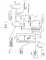
- FIG. 1 is an illustration primarily in block diagram form showing an embodiment of the fuel cell refueling station and system of the present invention;
- FIG. 2 is a schematic drawing of a first embodiment of the fuel cell refueling station of the present invention;
- FIG. 3 is a schematic drawing of a second embodiment of the fuel cell refueling station of the present invention;
- FIG. 4 is a schematic drawing of a third embodiment of the fuel cell refueling station of the present invention; and
- FIG. 5 is a schematic drawing of a fourth embodiment of the fuel cell refueling station of the present invention.
-
- As illustrated in FIG. 1, in accordance with the present invention,
tanker trucks 10a, 10b and 10c are filled with liquid natural gas (LNG) at a centralizedLNG production facility 20. The LNG tanker trucks are then dispatched to refueling stations 100a, 100b and 100c so that the LNG bulk tanks at the stations may be refilled. The refueling stations 100a, 100b and 100c may optionally include transmitters that communicate viarefueling station antennas LNG facility antenna 40 with a receiver at theLNG facility 20 so that the LNG tanker trucks may be automatically and timely dispatched so that the refueling stations may provide uninterrupted service. As an alternative to theantennas - Referring to FIG. 2, in an embodiment of the present invention, a
hydrogen refueling station 100 is built by retrofitting hydrogen processing components onto an already existing LNG dispensing station. The hydrogen refueling station has a bulkcryogenic storage tank 102 for storing liquid natural gas (LNG) typically at -260°F and approximately 100 psig as known in the art. As described with regard to FIG. 1, thebulk tank 102 is refilled by a tanker truck dispatched from a centralized LNG production facility. - The
bulk tank 102 is connected to a pump in asump 104, which in turn is connected to an LNG conditioning and dispensing portion of thestation 105. Examples of LNG conditioning and dispensing systems that are suitable for use as the LNG conditioning and dispensingportion 105 of thestation 100 are presented in commonly assigned U.S. Patent No. 6,354,088 to Emmer et al., U.S. Patent Nos. 5,421,160 and 5,537,824, both to Gustafson et al., U.S. Patent Nos. 5,121,609 and 5,231,838, both to Cieslukowski and U.S. Patent No. 5,228,295 to Gustafson. In addition, the dispensing portion may take the form of currently pending and commonly owned U.S. Patent Application No. 09/632,088. - To implement hydrogen dispensing, the
refueling station 100 has asupply line 106 connected to thebulk storage tank 102 that supplies LNG to an ambientair heat exchanger 108 where the temperature of the LNG is raised to 50°F. The warmed LNG is then routed to ahydrogen reformer 110 where the LNG is preferably mixed with steam. Whilehydrogen reformer 110 is discussed below in terms of a steam reformer, it is to be understood that alternative types of reformers that produce hydrogen from natural gas may be used without departing from the scope of the present invention. -
Reformer 110 produced hydrogen, and waste carbon dioxide, from the inputs of LNG and steam in the presence of a catalyst in accordance with the following endothermic reaction: - The
reformer 110 may be a tubular reformer or a plate-type reformer, both of which are well known in the art. Examples of tubular reformers are presented in U.S. Patent Nos. 4,810,485 to Marianowski et al., 4,838,897 to Amano et al. and 3,698,957 to Sanderson. Examples of plate-type reformers are presented in U.S. Patent Nos. 5,997,594 to Edlund et al. and 6,033,634 to Koga. In addition, reformers suitable for use in the station may be obtained from GTI/Mosaic Energy of Des Plaines, Illinois. - The
reformer 110 thus produces hydrogen gas at approximately 150°F in addition to waste carbon dioxide gas. The waste carbon dioxide is filtered out and exhausted. - Depending on the device selected for use as reformed 110, the hydrogen may require further filtration/purification as it could be contaminated with materials that would be detrimental to the electrical chemical reaction that occurs within the fuel cell onboard the vehicle being refueled. More specifically, some trace quantities of unreacted reactants and trace quantities of byproducts such as CO may result from steam reforming. Trace quantities of CO, certain concentrations of CO2 and, in some cases, unsaturated hydrocarbons and alcohols will poison a fuel cell.
- As a result, the
system 100 may optionally be provided with a purifier, indicated in phantom at 111. As is well known in the art,purifier 111 may include a pressure swing adsorption (PSA) stack arrangement. Alternatively, the purifier may use metallic foils or thin films, also well known in the art. - The hydrogen gas flows to a
high pressure compressor 112 which raises the pressure of the hydrogen gas to 5000 psi. The pressurized hydrogen is either stored ingas storage tubes 114 or flows to adispenser 116. A vehicle (not shown) can be connected to thedispenser 116 for receiving a supply of high pressure hydrogen gas. - Referring to FIG. 3, an alternative
embodiment refueling station 200 is shown with features similar to the features ofrefueling station 100 numbered the same. In this alternative, instead of exhausting the carbon dioxide into the atmosphere or waste removal devices, liquid CO2 is produced which can be used for dry ice, beverage production or any other known CO2 application. To provide the liquid CO2, the carbon dioxide produced at areformer 110 is routed to acompressor 204 and is compressed from 100 psig to 300 psig. The pressurized CO2 is then routed back to a heat exchanger 206 that uses the heat from the CO2 to warm the LNG first flowing toward thereformer 110. The exchanger 206 also cools the CO2 to below its critical temperature, at approximately 90°F, which converts it into liquid before it is stored in a dewar 208 for later dispensing. - Referring to FIG. 4, in another alternative embodiment,
refueling station 300 is a high efficiency station that routes the purified hydrogen from thereformer 110 back to aheat exchanger 302. At theexchanger 302, the heat from the hydrogen is used to heat the natural gas before it enters thereformer 110. The cooled hydrogen then is routed to thehigh pressure compressor 112 as withrefueling station 100. - Referring to FIG. 5, a
refueling station 400 cools the hydrogen in aheat exchanger 302 as withrefueling station 300, except that the cooled hydrogen then proceeds to a smallscale hydrogen liquifier 402. Theliquifier 402 further cools the hydrogen to -420°F and lowers the pressure to 20 psi. Such liquifiers are well known in the art. A dewar 404 for the liquid hydrogen is then used to store the hydrogen and keep it cool. The hydrogen then flows to aliquid hydrogen dispenser 406 for filling a vehicle (not shown) as needed. - It will be appreciated that many other configurations of LNG dispensing stations can be retrofitted or built new with a reformer and dispensing mechanisms to provide pure hydrogen. It will also be appreciated that any reformer or conversion device that strips pure hydrogen by cracking natural gas or methane can be used by the refueling station of the present invention to provide the hydrogen.
- The present invention thus offers a number of advantages over the prior art. First, the cost to add on a hydrogen production and dispensing equipment to the existing and growing infrastructure supplying bulk LNG is relatively low. Besides cost, relatively few significant physical restrictions are placed on the reformer at a refueling station, especially compared to a reformer placed onboard a vehicle. Also, for the same size tanker truck, transportation of LNG to the refueling station provides substantially more hydrogen than transporting previously purified liquid hydrogen (approximately one truck of LNG carries the same amount of hydrogen as three trucks of pure liquid hydrogen). Additionally, natural gas is 98% efficient when stripping hydrogen from natural gas leaving very little CO2 waste compared to methanol that is only 85% efficient. LNG is also relatively safer than the other possible source chemicals because of its high ignition energy.
- While the preferred embodiments of the invention have been shown and described, it will be apparent to those skilled in the art that changes and modifications may be made therein without departing from the spirit of the invention, the scope of which is defined by the appended claims.
Claims (30)
- A system for producing hydrogen and fueling vehicles which use hydrogen to produce power comprising:a. a bulk tank containing a supply of liquid natural gas;b. a heat exchanger in communication with the bulk tank, said heat exchanger receiving liquid natural gas from said bulk tank and warming it;c. a reformer in communication with the heat exchanger, said reformer receiving the warmed liquid natural gas from said heat exchanger and producing hydrogen gas therefrom; andd. a dispenser in communication with said reformer and adapted to dispense hydrogen produced by said reformer to the vehicles.
- The system of claim 1 further comprising a compressor in circuit between said reformer and said dispenser so that hydrogen gas from the reformer may be pressurized.
- The system of claim 2 further comprising gas storage tubes in circuit between said compressor and said dispenser so that pressurized hydrogen gas from the compressor may be stored.
- The system of claim 2 further comprising a purifier in circuit between said reformer and said compressor.
- The system of claim 1 further comprising a pump in communication with the bulk tank so that liquid natural gas from the bulk tank may be pumped to a use device.
- The system of claim 5 further comprising a sump with said pump positioned therein, said sump in communication with the bulk tank and receiving liquid natural gas therefrom so that the pump is at least partially submerged in the liquid natural gas.
- The system of claim 1 further comprising a liquid natural gas dispensing and conditioning portion in communication with the bulk tank so that liquid natural gas from the bulk tank may be conditioned and dispensed to a use device.
- The system of claim 1 wherein said reformer is a steam reformer and carbon dioxide is produced along with the hydrogen.
- The system of claim 8 wherein carbon dioxide from the reformer is directed to the heat exchanger and then a storage container so that the carbon dioxide is cooled by the liquid natural gas flowing through the heat exchanger and liquid carbon dioxide is formed in the heat exchanger and stored in the storage container for future use.
- The system of claim 9 further comprising a compressor in circuit between the reformer and the heat exchanger so that the carbon dioxide from the reformer is compressed prior to entering said heat exchanger.
- The system of claim 1 wherein hydrogen gas from the reformer is routed to the heat exchanger and cooled by the liquid natural gas flowing therethrough prior to traveling to the dispenser.
- The system of claim 11 further comprising a compressor in circuit between the heat exchanger and the dispenser so that the hydrogen is compressed after leaving the heat exchanger and before traveling to the dispenser.
- The system of claim 12 further comprising gas storage tubes in circuit between said compressor and said dispenser so that pressurized gas from the compressor may be stored.
- The system of claim 11 further comprising a liquifier in circuit between the heat exchanger and the dispenser so that the hydrogen is liquified after leaving the heat exchanger and before traveling to the dispenser.
- The system of claim 14 further comprising a liquid hydrogen dewar in circuit between the liquifier and the dispenser so that liquid hydrogen from the liquifier may be stored.
- A system for producing and fueling vehicles which use hydrogen to produce power comprising:a. a centralized liquid natural gas production facility;b. a tanker truck receiving liquid natural gas from said production facility; andc. a refueling station including:i) a bulk tank adapted to communicate with said tanker truck and containing a supply of liquid natural gas from said tanker truck;ii) a heat exchanger in communication with the bulk tank, said heat exchanger receiving liquid natural gas from said bulk tank and warming it;iii) a reformer in communication with the heat exchanger, said reformer receiving the warmed liquid natural gas from said heat exchanger and producing hydrogen therefrom; andiv) a dispenser in communication with said reformer and adapted to dispense hydrogen produced by said reformer to the vehicles.
- The system of claim 16 wherein the refueling station further includes a liquid natural gas dispensing and conditioning portion in communication with the bulk tank so that liquid natural gas from the bulk tank may be conditioned and dispensed to a use device.
- The system of claim 16 wherein the reformer of said refueling station is a steam reformer and carbon dioxide is produced along with the hydrogen.
- The system of claim 18 wherein carbon dioxide from the reformer is directed to the heat exchanger of the refueling station and then a storage container so that the carbon dioxide is cooled by the liquid natural gas flowing through the heat exchanger and liquid carbon dioxide is formed in the heat exchanger and stored in the storage container for future use.
- The system of claim 19 further comprising a compressor in circuit between the reformer and the heat exchanger so that the carbon dioxide from the reformer is compressed prior to entering said heat exchanger.
- The system of claim 16 wherein hydrogen gas from the refueling station reformer is routed to the refueling station heat exchanger and cooled by the liquid natural gas flowing therethrough prior to traveling to the dispenser.
- The system of claim 21 further comprising a compressor in circuit between the heat exchanger and the dispenser so that the hydrogen is compressed after leaving the heat exchanger and before traveling to the dispenser.
- The system of claim 21 further comprising a liquifier in circuit between the heat exchanger and the dispenser so that the hydrogen is liquified after leaving the heat exchanger and before traveling to the dispenser.
- The system of claim 16 further comprising means for the refueling station to contact the centralized liquid natural gas production facility so that liquid natural gas may automatically be reordered and dispatched.
- A method for fueling vehicles which use hydrogen to produce power comprising the steps of:a. storing liquid natural gas;b. warming the liquid natural gas;c. converting the warmed liquid natural gas to hydrogen gas; andd. dispensing the hydrogen to the vehicles.
- The method of claim 25 further comprising the step of transporting the liquid natural gas before storing it.
- The method of claim 25 further comprising the step of compressing the hydrogen gas prior to dispensing it to the vehicles.
- The method of claim 25 further comprising the step of storing the hydrogen gas before dispensing it to the vehicles.
- The method of claim 25 further comprising the step of liquifying the hydrogen before dispensing it to the vehicles.
- The method of claim 29 further comprising the step of storing the liquid hydrogen before dispensing it to the vehicles.
Applications Claiming Priority (2)
| Application Number | Priority Date | Filing Date | Title |
|---|---|---|---|
| US29847601P | 2001-06-15 | 2001-06-15 | |
| US298476P | 2001-06-15 |
Publications (2)
| Publication Number | Publication Date |
|---|---|
| EP1267432A2 true EP1267432A2 (en) | 2002-12-18 |
| EP1267432A3 EP1267432A3 (en) | 2005-03-30 |
Family
ID=23150680
Family Applications (1)
| Application Number | Title | Priority Date | Filing Date |
|---|---|---|---|
| EP02254177A Ceased EP1267432A3 (en) | 2001-06-15 | 2002-06-17 | Fuel cell refueling station and system |
Country Status (3)
| Country | Link |
|---|---|
| US (2) | US20030021743A1 (en) |
| EP (1) | EP1267432A3 (en) |
| JP (1) | JP2003118548A (en) |
Cited By (14)
| Publication number | Priority date | Publication date | Assignee | Title |
|---|---|---|---|---|
| WO2004113223A1 (en) * | 2003-06-26 | 2004-12-29 | Powergen International Pty Ltd | Reformate assisted combustion |
| WO2005019721A2 (en) * | 2003-07-03 | 2005-03-03 | Pinnacle West Capital Corporation | Hydrogen handling or dispensing system |
| EP1691127A1 (en) * | 2005-01-20 | 2006-08-16 | Air Products and Chemicals, Inc. | Method for delivering cryogenic fluid, in liquid or in gas phase, to a network of receiving fuel stations |
| WO2007114276A1 (en) * | 2006-03-30 | 2007-10-11 | Nippon Steel Engineering Co., Ltd. | Method for start-up of liquid fuel synthesis system, and liquid fuel synthesis system |
| WO2009046933A1 (en) * | 2007-10-02 | 2009-04-16 | Diehl Aerospace Gmbh | Mobile generator for supplying power to the on-board power supply system from ground, especially the on-board power supply system of a parked aircraft |
| CN101876398A (en) * | 2009-05-01 | 2010-11-03 | 丛洋 | Decompression and gas storage device, gas ejecting system and vehicle |
| WO2010124658A1 (en) * | 2009-05-01 | 2010-11-04 | Cong Yang | Pressure-reducing gas storage devic, gas injection system and automobile |
| CN101875300B (en) * | 2009-05-01 | 2014-01-29 | 丛洋 | Compressed gas supply system and compressed gas motor vehicle refrigerating system |
| US9444109B2 (en) | 2010-09-25 | 2016-09-13 | Huawei Technologies Co., Ltd. | System and method for supplying hydrogen gas, and hydrogen fuel cell system |
| CN106382458A (en) * | 2016-10-11 | 2017-02-08 | 诺威尔(天津)能源装备股份有限公司 | Closed-loop control based LNG immersed pump control system and control method thereof |
| US9617490B2 (en) | 2013-12-13 | 2017-04-11 | Exxonmobil Research And Engineering Company | Vehicle powertrain with onboard catalytic reformer |
| CN110736026A (en) * | 2019-10-24 | 2020-01-31 | 邳州亚联环保科技有限公司 | residual liquid recycling system |
| CN114909599A (en) * | 2022-05-09 | 2022-08-16 | 重庆大学 | Hydrogen storage tank for new energy automobile and use method thereof |
| CN116072921A (en) * | 2023-01-28 | 2023-05-05 | 深圳市氢蓝时代动力科技有限公司 | Hydrogen supply system and fuel cell |
Families Citing this family (25)
| Publication number | Priority date | Publication date | Assignee | Title |
|---|---|---|---|---|
| JP4619575B2 (en) * | 2001-06-15 | 2011-01-26 | 日本エア・リキード株式会社 | Hydrogen gas production method and hydrogen gas production facility |
| JP2004079262A (en) * | 2002-08-13 | 2004-03-11 | Mitsubishi Heavy Ind Ltd | Hydrogen-supply system and mobile hydrogen production equipment |
| FR2846958B1 (en) * | 2002-11-13 | 2005-08-26 | N Ghy | OXYGEN VALORIZATION FOR THE PRODUCTION OF HYDROGEN FROM HYDROCARBONS WITH CO2 SEQUESTRATION |
| JP4272922B2 (en) * | 2003-05-26 | 2009-06-03 | 本田技研工業株式会社 | Pure hydrogen production equipment |
| DE102005004665A1 (en) | 2005-02-02 | 2006-08-10 | Messer Group Gmbh | Method and device for filling pressure vessels with non-liquefied gases or gas mixtures |
| US20060236608A1 (en) * | 2005-04-22 | 2006-10-26 | Amjad Khan | System for dispensing hydrogen to a vehicle |
| US20060260330A1 (en) * | 2005-05-19 | 2006-11-23 | Rosetta Martin J | Air vaporizor |
| TWI296599B (en) * | 2005-06-13 | 2008-05-11 | Wisepoint Technology Co Ltd | Beam jet propellor |
| US20070084523A1 (en) * | 2005-09-23 | 2007-04-19 | Angstrom Power Incorporated | Systems and methods for replenishing fuel-cell-powered portable devices |
| FR2891347B1 (en) | 2005-09-28 | 2007-11-02 | Air Liquide | METHOD AND DEVICE FOR FILLING A PRESSURIZED GAS IN A RESERVOIR |
| AT502901B1 (en) * | 2005-10-31 | 2009-08-15 | Electrovac Ag | DEVICE FOR HYDROGEN MANUFACTURE |
| CA2539232C (en) * | 2006-03-22 | 2008-01-08 | Westport Research Inc. | Multi-fuel storage system and method of storing fuel in a multi-fuel storage system |
| US7849691B2 (en) * | 2006-10-03 | 2010-12-14 | Air Liquide Process & Construction, Inc. | Steam methane reforming with LNG regasification terminal for LNG vaporization |
| KR100818310B1 (en) | 2007-04-09 | 2008-04-02 | (주)덕양에너젠 | Alternating system for reformer of hydrogen station |
| CN100451438C (en) * | 2007-05-16 | 2009-01-14 | 马磊 | Automatic gasifying and gas adding device for energy saving type gasifying natural gas |
| FR2928716B1 (en) * | 2008-03-11 | 2012-12-28 | Air Liquide | DEVICE AND METHOD FOR FILLING A PRESSURIZED GAS IN A RESERVOIR |
| KR101402381B1 (en) * | 2013-04-11 | 2014-06-03 | 한국가스공사 | Remote place natural gas supply station using lng tank container and natural gas supply method using the same |
| DE102013020511A1 (en) | 2013-12-11 | 2015-06-11 | Karl Werner Dietrich | Storage power plant fuel cell |
| KR102306468B1 (en) * | 2016-07-06 | 2021-10-06 | 주식회사 싸이트로닉 | System using cold energy |
| FR3088415B1 (en) * | 2018-11-12 | 2020-10-23 | Air Liquide | PROCESS AND INSTALLATION FOR STORAGE AND DISTRIBUTION OF LIQUEFIED HYDROGEN |
| CN112028016A (en) * | 2020-09-16 | 2020-12-04 | 中国海洋石油集团有限公司 | Method for preparing hydrogen and food-grade dry ice for fuel cell by LNG |
| US20220349525A1 (en) * | 2021-04-30 | 2022-11-03 | The Claire Technologies Corporation | Fueling station for supply of liquid organic hydrogen carriers and method of operation |
| JP2022077296A (en) * | 2020-11-11 | 2022-05-23 | トヨタ自動車株式会社 | Navigation device |
| CA3227147A1 (en) | 2021-07-20 | 2023-01-26 | FirstElement Fuel, Inc. | Liquid hydrogen offloading |
| KR102379650B1 (en) * | 2021-11-16 | 2022-03-29 | 성우인스트루먼츠 주식회사 | Ambient type high-pressure hydrogen vaporizer and hydrogen charging apparatus using the same |
Citations (1)
| Publication number | Priority date | Publication date | Assignee | Title |
|---|---|---|---|---|
| EP0566151A1 (en) * | 1992-04-17 | 1993-10-20 | Praxair Technology, Inc. | Pumping of liquified gas |
Family Cites Families (21)
| Publication number | Priority date | Publication date | Assignee | Title |
|---|---|---|---|---|
| US3091593A (en) * | 1959-01-29 | 1963-05-28 | Azote & Prod Chim | Method for producing mixtures of hydrogen and carbon monoxide |
| US3698957A (en) * | 1970-12-16 | 1972-10-17 | United Aircraft Corp | Fuel cell system having a natural circulation boiler |
| US3798918A (en) * | 1971-04-15 | 1974-03-26 | Chicago Bridge & Iron Co | Method and apparatus for purifying natural gas to be liquefied and stored |
| JPS59141405A (en) * | 1983-02-02 | 1984-08-14 | Mitsubishi Heavy Ind Ltd | Production of liquid hydrogen |
| JPS61236601A (en) * | 1985-04-10 | 1986-10-21 | Hitachi Ltd | Steam reforming apparatus |
| US4810485A (en) * | 1986-08-25 | 1989-03-07 | Institute Of Gas Technology | Hydrogen forming reaction process |
| DE3809680A1 (en) * | 1988-03-17 | 1989-09-28 | Mannesmann Ag | PLANT FOR COMPRESSING HYDROGEN GAS |
| US5121609A (en) * | 1991-05-17 | 1992-06-16 | Minnesota Valley Engineering | No loss fueling station for liquid natural gas vehicles |
| US5228295A (en) * | 1991-12-05 | 1993-07-20 | Minnesota Valley Engineering | No loss fueling station for liquid natural gas vehicles |
| JPH05287284A (en) * | 1992-04-06 | 1993-11-02 | Mitsubishi Heavy Ind Ltd | Process for reforming liquefied natural gas |
| JPH05295374A (en) * | 1992-04-16 | 1993-11-09 | Mitsubishi Heavy Ind Ltd | Reforming of liquefied natural gas |
| US5360139A (en) * | 1993-01-22 | 1994-11-01 | Hydra Rig, Inc. | Liquified natural gas fueling facility |
| US5421160A (en) * | 1993-03-23 | 1995-06-06 | Minnesota Valley Engineering, Inc. | No loss fueling system for natural gas powered vehicles |
| JPH0892577A (en) * | 1994-09-26 | 1996-04-09 | Mitsubishi Heavy Ind Ltd | Method for reforming liquefied natural gas |
| US5516967A (en) * | 1995-01-30 | 1996-05-14 | Chemisar Laboratories Inc. | Direct conversion of methane to hythane |
| US5682750A (en) * | 1996-03-29 | 1997-11-04 | Mve Inc. | Self-contained liquid natural gas filling station |
| US5997594A (en) * | 1996-10-30 | 1999-12-07 | Northwest Power Systems, Llc | Steam reformer with internal hydrogen purification |
| JPH10265202A (en) * | 1997-03-25 | 1998-10-06 | Ishikawajima Harima Heavy Ind Co Ltd | Hydrogen producing device |
| TW359736B (en) * | 1997-06-20 | 1999-06-01 | Exxon Production Research Co | Systems for vehicular, land-based distribution of liquefied natural gas |
| CA2271448A1 (en) * | 1999-05-12 | 2000-11-12 | Stuart Energy Systems Inc. | Energy distribution network |
| US6354088B1 (en) * | 2000-10-13 | 2002-03-12 | Chart Inc. | System and method for dispensing cryogenic liquids |
-
2002
- 2002-06-14 US US10/172,367 patent/US20030021743A1/en not_active Abandoned
- 2002-06-17 EP EP02254177A patent/EP1267432A3/en not_active Ceased
- 2002-06-17 JP JP2002175395A patent/JP2003118548A/en active Pending
-
2005
- 2005-12-16 US US11/303,692 patent/US20060090399A1/en not_active Abandoned
Patent Citations (1)
| Publication number | Priority date | Publication date | Assignee | Title |
|---|---|---|---|---|
| EP0566151A1 (en) * | 1992-04-17 | 1993-10-20 | Praxair Technology, Inc. | Pumping of liquified gas |
Non-Patent Citations (6)
| Title |
|---|
| MOORE R B ET AL: "Hydrogen infrastructure for fuel cell transportation" INTERNATIONAL JOURNAL OF HYDROGEN ENERGY, ELSEVIER SCIENCE PUBLISHERS B.V., BARKING, GB, vol. 23, no. 7, July 1998 (1998-07), pages 617-620, XP004117690 ISSN: 0360-3199 * |
| OGDEN J M: "Developing an infrastructure for hydrogen vehicles: a Southern California case study" INTERNATIONAL JOURNAL OF HYDROGEN ENERGY, ELSEVIER SCIENCE PUBLISHERS B.V., BARKING, GB, vol. 24, no. 8, August 1999 (1999-08), pages 709-730, XP004173555 ISSN: 0360-3199 * |
| PATENT ABSTRACTS OF JAPAN vol. 008, no. 266 (C-255), 6 December 1984 (1984-12-06) -& JP 59 141405 A (MITSUBISHI JUKOGYO KK), 14 August 1984 (1984-08-14) * |
| PATENT ABSTRACTS OF JAPAN vol. 018, no. 082 (C-1164), 10 February 1994 (1994-02-10) -& JP 05 287284 A (MITSUBISHI HEAVY IND LTD), 2 November 1993 (1993-11-02) * |
| PATENT ABSTRACTS OF JAPAN vol. 018, no. 097 (C-1167), 17 February 1994 (1994-02-17) -& JP 05 295374 A (MITSUBISHI HEAVY IND LTD), 9 November 1993 (1993-11-09) * |
| PATENT ABSTRACTS OF JAPAN vol. 1996, no. 08, 30 August 1996 (1996-08-30) -& JP 08 092577 A (MITSUBISHI HEAVY IND LTD), 9 April 1996 (1996-04-09) * |
Cited By (23)
| Publication number | Priority date | Publication date | Assignee | Title |
|---|---|---|---|---|
| WO2004113223A1 (en) * | 2003-06-26 | 2004-12-29 | Powergen International Pty Ltd | Reformate assisted combustion |
| US7536981B2 (en) | 2003-06-26 | 2009-05-26 | Powergen International Pty, Ltd. | Reformate assisted combustion |
| WO2005019721A2 (en) * | 2003-07-03 | 2005-03-03 | Pinnacle West Capital Corporation | Hydrogen handling or dispensing system |
| WO2005019721A3 (en) * | 2003-07-03 | 2005-11-10 | Pinnacle West Capital Corp | Hydrogen handling or dispensing system |
| US7275569B2 (en) | 2003-07-03 | 2007-10-02 | Arizona Public Service Company | Hydrogen handling or dispensing system |
| US7287558B2 (en) | 2003-07-03 | 2007-10-30 | Arizona Public Service Company | Hydrogen handling or dispensing system |
| EP1691127A1 (en) * | 2005-01-20 | 2006-08-16 | Air Products and Chemicals, Inc. | Method for delivering cryogenic fluid, in liquid or in gas phase, to a network of receiving fuel stations |
| US7264025B2 (en) | 2005-01-20 | 2007-09-04 | Air Products And Chemicals, Inc. | Optimized cryogenic fluid supply method |
| WO2007114276A1 (en) * | 2006-03-30 | 2007-10-11 | Nippon Steel Engineering Co., Ltd. | Method for start-up of liquid fuel synthesis system, and liquid fuel synthesis system |
| WO2009046933A1 (en) * | 2007-10-02 | 2009-04-16 | Diehl Aerospace Gmbh | Mobile generator for supplying power to the on-board power supply system from ground, especially the on-board power supply system of a parked aircraft |
| CN101876398A (en) * | 2009-05-01 | 2010-11-03 | 丛洋 | Decompression and gas storage device, gas ejecting system and vehicle |
| WO2010124658A1 (en) * | 2009-05-01 | 2010-11-04 | Cong Yang | Pressure-reducing gas storage devic, gas injection system and automobile |
| US8534059B2 (en) | 2009-05-01 | 2013-09-17 | Yang Cong | Pressure reducing gas storage device, air-jet system, and motor vehicle |
| CN101875300B (en) * | 2009-05-01 | 2014-01-29 | 丛洋 | Compressed gas supply system and compressed gas motor vehicle refrigerating system |
| US9444109B2 (en) | 2010-09-25 | 2016-09-13 | Huawei Technologies Co., Ltd. | System and method for supplying hydrogen gas, and hydrogen fuel cell system |
| US9617490B2 (en) | 2013-12-13 | 2017-04-11 | Exxonmobil Research And Engineering Company | Vehicle powertrain with onboard catalytic reformer |
| US10001091B2 (en) | 2013-12-13 | 2018-06-19 | Exxonmobil Research And Engineering Company | Vehicle powertrain with onboard catalytic reformer |
| CN106382458A (en) * | 2016-10-11 | 2017-02-08 | 诺威尔(天津)能源装备股份有限公司 | Closed-loop control based LNG immersed pump control system and control method thereof |
| CN110736026A (en) * | 2019-10-24 | 2020-01-31 | 邳州亚联环保科技有限公司 | residual liquid recycling system |
| CN114909599A (en) * | 2022-05-09 | 2022-08-16 | 重庆大学 | Hydrogen storage tank for new energy automobile and use method thereof |
| CN114909599B (en) * | 2022-05-09 | 2023-08-25 | 重庆大学 | Hydrogen storage tank for new energy automobile and application method thereof |
| CN116072921A (en) * | 2023-01-28 | 2023-05-05 | 深圳市氢蓝时代动力科技有限公司 | Hydrogen supply system and fuel cell |
| CN116072921B (en) * | 2023-01-28 | 2023-07-04 | 深圳市氢蓝时代动力科技有限公司 | Hydrogen supply system and fuel cell |
Also Published As
| Publication number | Publication date |
|---|---|
| US20060090399A1 (en) | 2006-05-04 |
| EP1267432A3 (en) | 2005-03-30 |
| US20030021743A1 (en) | 2003-01-30 |
| JP2003118548A (en) | 2003-04-23 |
Similar Documents
| Publication | Publication Date | Title |
|---|---|---|
| EP1267432A2 (en) | Fuel cell refueling station and system | |
| US6886609B2 (en) | Mobile hydrogen generation and supply system | |
| US7878280B2 (en) | Low pressure hydrogen fueled vehicle and method of operating same | |
| Moore et al. | Hydrogen infrastructure for fuel cell transportation | |
| EP1394105A1 (en) | Hydrogen supply system and mobile hydrogen production system | |
| US20030008183A1 (en) | Zero/low emission and co-production energy supply station | |
| CN100449841C (en) | Zero/low discharge and co-production type energy supply station | |
| US20090151809A1 (en) | Method for filling gaseous hydrogen storage tanks | |
| US20090304574A1 (en) | Configurations And Methods Of Hydrogen Fueling | |
| US8061392B2 (en) | Variable volume hydrogen storage | |
| Böhm et al. | Review and comparison of worldwide hydrogen activities in the rail sector with special focus on on-board storage and refueling technologies | |
| JP2005145748A (en) | Hydrogen production apparatus | |
| US20040031388A1 (en) | Zero/low emission and co-production energy supply station | |
| Zur Megede | Fuel processors for fuel cell vehicles | |
| CN104627962A (en) | Method and system for in situ hydrogen production by using liquefied natural gas on hydrogen fuel cell vehicle | |
| US20040204503A1 (en) | Method and apparatus for storage and transportation of hydrogen | |
| US6619333B2 (en) | Apparatus and method for using the existing hydrocarbon distribution, storage and dispensing infrastructures for the production, distribution and dispensing of hydrogen | |
| JP2002337999A (en) | Fuel feeding system | |
| Raman | The hydrogen fuel option for fuel cell vehicle fleets | |
| US20110064647A1 (en) | Method for storage and transportation of hydrogen | |
| Chiesa et al. | 15 Hydrogen for mobility | |
| WO2022226380A1 (en) | Systems and methods for producing hydrogen and byproducts from natural gas | |
| WO2007109034A2 (en) | Low pressure hydrogen fueled vehicle and method of operating same | |
| CN116924332A (en) | Method for producing high-purity hydrogen based on hydrogen-rich raw material gas | |
| Ahluwalia et al. | Argonne National Laboratory, Nuclear Engineering Division, 9700 South Cass Avenue, Lemont, IL 60439, USA |
Legal Events
| Date | Code | Title | Description |
|---|---|---|---|
| PUAI | Public reference made under article 153(3) epc to a published international application that has entered the european phase |
Free format text: ORIGINAL CODE: 0009012 |
|
| AK | Designated contracting states |
Kind code of ref document: A2 Designated state(s): AT BE CH CY DE DK ES FI FR GB GR IE IT LI LU MC NL PT SE TR |
|
| AX | Request for extension of the european patent |
Free format text: AL;LT;LV;MK;RO;SI |
|
| RIN1 | Information on inventor provided before grant (corrected) |
Inventor name: BARR, DAVID G. Inventor name: WILKSTROM, JON P |
|
| PUAL | Search report despatched |
Free format text: ORIGINAL CODE: 0009013 |
|
| AK | Designated contracting states |
Kind code of ref document: A3 Designated state(s): AT BE CH CY DE DK ES FI FR GB GR IE IT LI LU MC NL PT SE TR |
|
| AX | Request for extension of the european patent |
Extension state: AL LT LV MK RO SI |
|
| RIC1 | Information provided on ipc code assigned before grant |
Ipc: 7C 10K 3/04 B Ipc: 7B 01D 53/62 B Ipc: 7F 17C 7/04 B Ipc: 7F 17C 7/02 B Ipc: 7H 01M 8/06 A |
|
| 17P | Request for examination filed |
Effective date: 20050727 |
|
| AKX | Designation fees paid |
Designated state(s): AT BE CH CY DE DK ES FI FR GB GR IE IT LI LU MC NL PT SE TR |
|
| STAA | Information on the status of an ep patent application or granted ep patent |
Free format text: STATUS: THE APPLICATION HAS BEEN REFUSED |
|
| 18R | Application refused |
Effective date: 20080428 |