EP1267050A1 - Dispositif perfectionné de régulation thermique à stockage d'énergie pour véhicule automobile - Google Patents
Dispositif perfectionné de régulation thermique à stockage d'énergie pour véhicule automobile Download PDFInfo
- Publication number
- EP1267050A1 EP1267050A1 EP02291454A EP02291454A EP1267050A1 EP 1267050 A1 EP1267050 A1 EP 1267050A1 EP 02291454 A EP02291454 A EP 02291454A EP 02291454 A EP02291454 A EP 02291454A EP 1267050 A1 EP1267050 A1 EP 1267050A1
- Authority
- EP
- European Patent Office
- Prior art keywords
- branch
- energy storage
- thermal regulation
- heat transfer
- transfer liquid
- Prior art date
- Legal status (The legal status is an assumption and is not a legal conclusion. Google has not performed a legal analysis and makes no representation as to the accuracy of the status listed.)
- Granted
Links
Images



Classifications
-
- B—PERFORMING OPERATIONS; TRANSPORTING
- B60—VEHICLES IN GENERAL
- B60H—ARRANGEMENTS OF HEATING, COOLING, VENTILATING OR OTHER AIR-TREATING DEVICES SPECIALLY ADAPTED FOR PASSENGER OR GOODS SPACES OF VEHICLES
- B60H1/00—Heating, cooling or ventilating devices
- B60H1/00492—Heating, cooling or ventilating devices comprising regenerative heating or cooling means, e.g. heat accumulators
-
- B—PERFORMING OPERATIONS; TRANSPORTING
- B60—VEHICLES IN GENERAL
- B60H—ARRANGEMENTS OF HEATING, COOLING, VENTILATING OR OTHER AIR-TREATING DEVICES SPECIALLY ADAPTED FOR PASSENGER OR GOODS SPACES OF VEHICLES
- B60H1/00—Heating, cooling or ventilating devices
- B60H1/02—Heating, cooling or ventilating devices the heat being derived from the propulsion plant
- B60H1/025—Heating, cooling or ventilating devices the heat being derived from the propulsion plant from both the cooling liquid and the exhaust gases of the propulsion plant
-
- F—MECHANICAL ENGINEERING; LIGHTING; HEATING; WEAPONS; BLASTING
- F01—MACHINES OR ENGINES IN GENERAL; ENGINE PLANTS IN GENERAL; STEAM ENGINES
- F01P—COOLING OF MACHINES OR ENGINES IN GENERAL; COOLING OF INTERNAL-COMBUSTION ENGINES
- F01P11/00—Component parts, details, or accessories not provided for in, or of interest apart from, groups F01P1/00 - F01P9/00
- F01P11/14—Indicating devices; Other safety devices
- F01P11/20—Indicating devices; Other safety devices concerning atmospheric freezing conditions, e.g. automatically draining or heating during frosty weather
-
- F—MECHANICAL ENGINEERING; LIGHTING; HEATING; WEAPONS; BLASTING
- F01—MACHINES OR ENGINES IN GENERAL; ENGINE PLANTS IN GENERAL; STEAM ENGINES
- F01P—COOLING OF MACHINES OR ENGINES IN GENERAL; COOLING OF INTERNAL-COMBUSTION ENGINES
- F01P5/00—Pumping cooling-air or liquid coolants
- F01P5/10—Pumping liquid coolant; Arrangements of coolant pumps
- F01P2005/105—Using two or more pumps
-
- F—MECHANICAL ENGINEERING; LIGHTING; HEATING; WEAPONS; BLASTING
- F01—MACHINES OR ENGINES IN GENERAL; ENGINE PLANTS IN GENERAL; STEAM ENGINES
- F01P—COOLING OF MACHINES OR ENGINES IN GENERAL; COOLING OF INTERNAL-COMBUSTION ENGINES
- F01P5/00—Pumping cooling-air or liquid coolants
- F01P5/10—Pumping liquid coolant; Arrangements of coolant pumps
- F01P5/12—Pump-driving arrangements
- F01P2005/125—Driving auxiliary pumps electrically
-
- F—MECHANICAL ENGINEERING; LIGHTING; HEATING; WEAPONS; BLASTING
- F01—MACHINES OR ENGINES IN GENERAL; ENGINE PLANTS IN GENERAL; STEAM ENGINES
- F01P—COOLING OF MACHINES OR ENGINES IN GENERAL; COOLING OF INTERNAL-COMBUSTION ENGINES
- F01P7/00—Controlling of coolant flow
- F01P7/14—Controlling of coolant flow the coolant being liquid
- F01P2007/146—Controlling of coolant flow the coolant being liquid using valves
-
- F—MECHANICAL ENGINEERING; LIGHTING; HEATING; WEAPONS; BLASTING
- F01—MACHINES OR ENGINES IN GENERAL; ENGINE PLANTS IN GENERAL; STEAM ENGINES
- F01P—COOLING OF MACHINES OR ENGINES IN GENERAL; COOLING OF INTERNAL-COMBUSTION ENGINES
- F01P11/00—Component parts, details, or accessories not provided for in, or of interest apart from, groups F01P1/00 - F01P9/00
- F01P11/14—Indicating devices; Other safety devices
- F01P2011/205—Indicating devices; Other safety devices using heat-accumulators
-
- F—MECHANICAL ENGINEERING; LIGHTING; HEATING; WEAPONS; BLASTING
- F01—MACHINES OR ENGINES IN GENERAL; ENGINE PLANTS IN GENERAL; STEAM ENGINES
- F01P—COOLING OF MACHINES OR ENGINES IN GENERAL; COOLING OF INTERNAL-COMBUSTION ENGINES
- F01P2060/00—Cooling circuits using auxiliaries
- F01P2060/08—Cabin heater
-
- F—MECHANICAL ENGINEERING; LIGHTING; HEATING; WEAPONS; BLASTING
- F01—MACHINES OR ENGINES IN GENERAL; ENGINE PLANTS IN GENERAL; STEAM ENGINES
- F01P—COOLING OF MACHINES OR ENGINES IN GENERAL; COOLING OF INTERNAL-COMBUSTION ENGINES
- F01P2060/00—Cooling circuits using auxiliaries
- F01P2060/16—Outlet manifold
-
- F—MECHANICAL ENGINEERING; LIGHTING; HEATING; WEAPONS; BLASTING
- F01—MACHINES OR ENGINES IN GENERAL; ENGINE PLANTS IN GENERAL; STEAM ENGINES
- F01P—COOLING OF MACHINES OR ENGINES IN GENERAL; COOLING OF INTERNAL-COMBUSTION ENGINES
- F01P2060/00—Cooling circuits using auxiliaries
- F01P2060/18—Heater
-
- F—MECHANICAL ENGINEERING; LIGHTING; HEATING; WEAPONS; BLASTING
- F01—MACHINES OR ENGINES IN GENERAL; ENGINE PLANTS IN GENERAL; STEAM ENGINES
- F01P—COOLING OF MACHINES OR ENGINES IN GENERAL; COOLING OF INTERNAL-COMBUSTION ENGINES
- F01P7/00—Controlling of coolant flow
- F01P7/14—Controlling of coolant flow the coolant being liquid
- F01P7/16—Controlling of coolant flow the coolant being liquid by thermostatic control
- F01P7/165—Controlling of coolant flow the coolant being liquid by thermostatic control characterised by systems with two or more loops
Definitions
- the present invention relates to an improved regulation device thermal energy storage for a motor vehicle.
- thermal energy storage means thermally coupled to a liquid circuit cooling of this engine.
- the coolant is usually a mixture of water and antifreeze (glycol).
- the thermal energy storage means used for this application are for example of two types.
- the means of the first type include a heat accumulator latent that can transfer heat to the coolant in the motor by phase change (liquid-> solid) of a salt.
- the means of the second type include a mixture of a suitable solid and gas capable of transfer heat to the engine coolant by creating a exothermic reaction. These reactions are reversible by post-regeneration.
- the coolant When starting the vehicle, the coolant, still cold in leaving the engine, is circulated by an electric pump through the means energy storage. These transfer calories to the cooling water by convection. Heat transfer to the coolant is rapid and allows for example to raise the coolant temperature by around 65 ° C in less than 10 seconds.
- the thermal energy storage means To be able to carry out a new heating cycle of the cooling when the vehicle is next started, the thermal energy storage means. This regeneration is generally carried out when the engine is sufficiently hot, by supplying energy to the storage means via the coolant.
- the regeneration of energy storage means from first type produces the return of salt in liquid phase.
- the regeneration of the means of energy storage of the second type produces the return of solid and gas to their initial state
- the thermal regulation branch is a branch of the coolant circuit of an internal combustion engine vehicle.
- the energy storage means are intended to be regenerated by calories taken from an exhaust gas circuit emitted by the engine at internal combustion.
- the energy storage means are coupled thermally to both the engine cooling system and the gas system exhaust. This poses problems of implantation of the storage means of energy in the vehicle, these storage means being liable to be clogged by exhaust gas leaks passing through them.
- the object of the invention is to propose a thermal regulation device for motor vehicle comprising energy storage means capable of being regenerated by removal of calories, as the case may be, from the exhaust gases or in the engine coolant, the energy storage means being simple to install in the vehicle and protected from the risk of fouling, the thermal regulation device capable of supplying calories to the engine or the passenger compartment of the vehicle even when this engine is stopped.
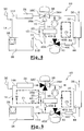
- FIGS. 1 to 5 show a thermal regulation device for a motor vehicle according to a first embodiment of the invention, designated by the general reference 10.
- This device 10 includes a heat transfer liquid circuit 12 comprising a thermal regulation branch 14, two branches 16,18 provided with means for energy storage 20 common to the two branches 16,18, say first and second branches 16, 18 for energy storage, and a branch 22 for regenerating the means energy storage 20 of the second energy storage branch 18.
- Each branch 14, 16, 18, 22 has upstream and downstream ends between which flows the heat transfer liquid in the direction indicated by the arrows on the FIGS. Note that the two upstream and downstream ends of the regeneration branch 22 are reversible.
- the thermal regulation branch 14 includes an upstream part 14A fitted with an air heater 24 for thermal regulation of a passenger compartment of the connected vehicle to a downstream part 14B for thermal regulation.
- This downstream part 14B comprises a vehicle internal combustion engine 26, the temperature of which is to be regulated, and a mechanical pump 28 for driving the heat transfer liquid in the branch of thermal regulation 14.
- This pump 28, driven by the motor 26, is fixed so classic on the latter.
- the heat transfer liquid circulating in the circuit 12 is a liquid engine 26, in particular a mixture of water and antifreeze (glycol).
- the circuit 12 is connected to a pipe 30 for supplying coolant.
- the energy storage means 20 include two connected inputs respectively at the two upstream ends of the first 16 and second 18 branches of energy storage, and two outputs connected respectively to the two downstream ends of these first 16 and second 18 branches of energy storage.
- the energy storage means 20 are of a conventional type, for example of the latent heat accumulator type capable of transferring heat to the engine coolant by phase change (liquid -> solid) of a salt.
- the energy storage means 20 can be of the heat type sensitive (hot water or solid / gas reaction).
- the second branch 18 of energy storage comprises a pump electric 32 for carrying the heat transfer liquid connected to the storage means of energy 20, downstream of these.
- the regeneration branch 22 comprises means for taking off exhaust calories comprising, in the examples illustrated, an exchanger thermal 34 heat transfer liquid / exhaust gas emitted by the combustion engine internal 26.
- a branch 36 for circulation of the exhaust gases through the exchanger 34 is shown diagrammatically in the figures.
- the first branch 16 of energy storage is likely to be connected to the thermal regulation branch 14, so as to form a loop C1 of circulation of heat transfer liquid as shown in broken lines in the figure 1 or 3.
- the second branch 18 of energy storage is susceptible to be selectively connected, on the one hand, to the thermal regulation branch 14, to so as to form a loop C2 for circulation of heat transfer liquid as shown in broken lines in FIG. 5, and, on the other hand, to the regeneration branch 22, of so as to form a loop C3 for circulation of heat transfer liquid as shown in broken lines in Figure 3 or 4.
- the two branches 16,18 of energy storage are susceptible to be isolated from the thermal regulation 14 and regeneration 22 branches so that the circuit 12 forms a loop C4 for circulation of the heat transfer liquid, such that shown in broken lines in Figure 2, in which the branch of regeneration 22 is connected to the thermal regulation branch 14.
- the device 10 comprises two valves 38.40, of the three-way type.
- a first valve 38 is provided with a first channel 38A connected to a downstream end of the first energy storage branch 16, of a second channel 38B connected to a downstream end of the second branch 18 of energy storage and at a first end of the regeneration branch 22, and a third path 38C connected to an upstream end of the thermal regulation branch 14.
- the second valve 40 is provided with a first channel 40A connected to a downstream end of the thermal regulation branch 14, of a second channel 40B connected to an upstream end of the second energy storage branch 18, and a third track 40C connected to the second end of the branch of regeneration 22.
- thermal regulation device 10 according to the first embodiment of the invention with reference to FIGS. 1 to 5 in which the open channels of the valves 38, 40 are blackened.
- the energy storage means 20 are initially loaded.
- the device regulator 10 When starting the vehicle (engine 26 in operation), the device regulator 10 is initially set in the operating configuration illustrated in FIG. 1.
- the valves 38.40 are adjusted so as, on the one hand, to be connected the first branch 16 of energy storage to the thermal regulation branch 14 and, on the other hand, to isolate the second branch 18 of energy storage from the circuit heat transfer liquid 12.
- the mechanical pump 28 is activated due to the operation of the motor 26 while the electric pump 32 is stopped.
- Storage means of energy 20 are discharged by transferring the calories they have stored in the heat transfer liquid circulating through the air heater 24 and the motor 26 (loop C1 illustrated in Figure 1), in order to heat the passenger compartment and accelerate the temperature rise of the motor 26.
- the valves 38.40 are adjusted so as to isolate the two storage branches 16.18 energy from the heat transfer liquid circuit 12 (the electric pump 32 is stopped) and, on the other hand, to connect the regeneration branch 22 to the regulation branch 14.
- the heat transfer liquid circulates in the circuit 12 in accordance with the loop C4 illustrated in FIG. 2, so that this heat transfer liquid takes up the calories in the exhaust gas, via the exchanger 34, and returns them, on the one hand, to the passenger compartment, via the air heater 24, and on the other hand, the engine 26.
- 38.40 valves are set as shown in Figure 3.
- the first branch 16 of energy storage is connected to the thermal regulation branch 14 to allow in particular the heat transfer liquid (hot enough) to heat the passenger compartment (loop C1) and, on the other hand, the second energy storage branch 18 is connected to the regeneration branch 22 for recharge the energy storage means 20 using the calories taken by the heat transfer liquid in the exhaust gas (loop C3).
- the electric pump 32 is activated.
- the valves 38.40 are again adjusted as in Figure 1.
- the heat transfer liquid which flows along the loop C1
- the heater 24 (usually comprising an exchanger thermal coolant / air associated with a fan) is generally stopped (fan stopped), so that the coolant circulating through this heater 24 does not dissipate calories in the passenger compartment.
- the thermal regulation device 10 When starting the vehicle, the thermal regulation device 10 is initially set in the operating configuration illustrated in FIG. 1.
- the energy storage means 20 are discharged by transferring the calories they have stored in the heat transfer fluid flowing through the engine 26 (loop C1) in order to accelerate the rise in temperature of the engine 26.
- the coolant does not dissipates practically no calories in the air heater 24 since the latter is at judgment.
- valves 38.40 are adjusted by on the one hand, to isolate the first branch 16 of energy storage from circuit 12 of heat transfer liquid and, on the other hand, to connect the second storage branch 18 of energy to the regeneration branch 22.
- the heat transfer liquid driven by the pump electric 32, circulates in circuit 12 along loop C3 illustrated in FIG. 4, if although this heat transfer liquid takes calories from the exhaust gases, by through the exchanger 34, and returns them to the energy storage means 20 in order to recharge them.
- the second charging phase is triggered as soon as the temperature of the heat transfer liquid reaches a desired value, for example as soon as the temperature of the heat transfer liquid at the outlet of the engine 26 is sufficient (for example equal to approximately 83 ° C) or as soon as the temperature of the heat transfer liquid at the outlet of the exchanger 34 reaches a value close to the boiling point of this heat transfer liquid (for example 110 ° C).
- valves 38.40 are at again set as in Figure 1.
- the heat transfer liquid which circulates according to the loop C1 transfers calories to the energy storage means 20 in order to complete reload these.
- the energy storage means 20 are initially discharged.
- the thermal regulation device 10 When starting the vehicle, the thermal regulation device 10 is initially set in the operating configuration illustrated in Figure 2 (described previously), so that the heat transfer liquid, circulating along the loop C4, takes calories from the exhaust gases, via the exchanger 34, and restores them, on the one hand, to the passenger compartment, via the air heater 24, and on the other hand hand, to engine 26.
- 38.40 valves are set in the configuration illustrated in Figure 3 (described previously).
- the heat transfer liquid hot enough heats the passenger compartment by yielding calories via the air heater 24 (loop C1) and, on the other hand, the energy storage means 20 are recharged using calories taken up by the heat transfer liquid in the gases exhaust via the exchanger 34 (loop C3).
- the valves 38.40 are adjusted as in FIG. 1.
- the heat transfer liquid which circulates according to the loop C1 transfers calories to the energy storage means 20 in order to complete reload these.
- the thermal regulation device 10 When starting the vehicle, the thermal regulation device 10 is initially set in the operating configuration illustrated in FIG. 4. Thus, the coolant circulates in circuit 12 along loop C3, so that this liquid coolant takes calories from the exhaust gas through the exchanger 34, and returns them to the energy storage means 20 so as to recharge.
- the valves 38.40 are adjusted as in FIG. 1.
- the heat transfer liquid which circulates along the loop C1 yields calories to the energy storage means 20 in order to complete recharging the latter.
- the energy storage means 20 are initially loaded and the engine 26 is stopped.
- the thermal regulation device 10 may be set in the operating configuration illustrated in Figure 5.
- the valves 38.40 are adjusted so as, on the one hand, to isolate the first branch 16 of energy storage of the circuit 12 of heat transfer liquid and, on the other hand, to connect the second branch 18 of energy storage to the thermal regulation branch 14.
- the heat transfer liquid is entrained in the branches 16 and 14, according to the loop C2, by the electric pump 32 replacing the mechanical pump 28 which is at judgment.
- This operating configuration allows, if necessary, to heat the passenger compartment while the engine 26 is stopped (the coolant gives way to the passenger compartment, via the air heater 24, calories taken from the storage means 20).
- the valves 38, 40 are controlled by conventional means electrical, mechanical, thermomechanical or pneumatic.
- the valves 38.40 can be of proportional type to allow the establishment of configurations of operation of the device 10 relatively complex allowing, for example, recharge the energy storage means 20 while heating the passenger compartment using calories taken from the exhaust gases, by controlling the flow of liquid coolant passing through these energy storage means 20.
- the circuit 12 of the heat transfer liquid of the device 10 according to the second mode embodiment of the invention, illustrated in FIG. 6, comprises means 42 for bypass of the downstream thermal regulation part 14B, directly connecting a outlet of the air heater 24 with an inlet of the energy storage means 20 of the second branch 18 of energy storage.
- the bypass means 42 illustrated in FIG. 6 allow, when the passenger compartment of the vehicle is heated with calories from the means of energy storage 20 (loops C2, C1), to avoid dissipation in the motor 26 of calories from these energy storage means 20.
- the first 16 and second 18 branches energy storage means 20A, 20B energy storage means separated.
- the size of the means 20A or of the means 20B is generally lower than that of common means 20.
- the storage means separate energy sources 20A, 20B are more efficient and easier to manage than the means of common energy storage 20, in particular when the device 10 is adjusted so as to heat the passenger compartment when starting the engine in very climatic conditions cold or cold.
- the regeneration branch 22 includes an additional heater 44 for thermal regulation of the passenger compartment.
- This heater 44 is connected in series to the heat exchanger 34 heat transfer liquid / gas exhaust.
- the air heater 44 is connected, on the one hand, to the third channel 40C from the second valve 40 and, on the other hand, to the heat exchanger 34.
- the two air heaters 24, 44 can be arranged in a duct air intake, one upstream of the other, according to a choice to be determined by a person skilled in the art depending on the desired optimization of the regulatory device thermal 10 in the preferred operating configurations.
- the two air heaters 24, 44 can be arranged in a unit common or in separate units.
- the two unit heaters 24, 44 may include a common fan.
- a fan will be associated with each air heater 24, 44.
- thermal regulation device 10 comprises means 43 for deriving means 20 for energy storage in the first energy storage branch 16.
- the bypass means 43 are activated using conventional means 43A comprising, for example a three-way valve. These activation means 43A can be activated automatically under the effect, for example, of an expandable wax conventional whose melting temperature substantially coincides with the temperature of transition from the solid phase to the liquid phase of a salt forming a heat accumulator latent in the energy storage means 20.
- the energy storage means 20 are initially charged and the climatic conditions are very cold (temperature of the air surrounding the vehicle close to -18 ° C).
- the operation described below proposes a sequence of phases of operation in a sequence that can last for example ten minutes.
- the thermal control device 10 is initially set in the configuration of operation illustrated in FIG. 8.
- the valves 38, 40 are adjusted so as to share, to isolate the first branch 16 of energy storage of the circuit 12 of liquid on the other hand, to connect the second branch 18 of energy storage to the regeneration branch 22.
- the electric pump 32 -activated by a user, by example, using a control key- drives the heat transfer liquid into the circuit 12 along the loop C3 illustrated in FIG. 8.
- the energy storage means 20 are discharged by transferring the calories they have stored in the coolant flowing through the additional heater 44, to heat the passenger compartment.
- the duration of this first phase is preferably relatively short, for example equal to approximately 2 minutes.
- valves 38, 40 are adjusted as illustrated in FIG. 9.
- the first branch 16 of energy storage is connected to the branch of thermal regulation 14 to allow in particular the heat transfer liquid to heat the passenger compartment (loop C1) and, on the other hand, the second branch 18 of energy storage is connected to the regeneration branch 22 as during the first phase of operation described above (loop C3).
- the duration of this second phase is for example equal to approximately 2 minutes.
- bypass means 43 are activated by so as to prevent the heat transfer liquid flowing in the first branch 16 of energy storage does not dissipate calories in the energy storage means 20.
- the second operating phase is followed by the third and fourth phases during which the quantity of calories conveyed in the downstream part 14B of the branch 14 of thermal regulation of the motor 26 and in the branch 36 of exhaust gas circulation, this by promoting the overconsumption of engine 26 by a conventional post-injection or delay process in advance of injection.
- moderate overconsumption is imposed to the engine 26, causing for example an increase in the temperature in the gases exhaust of around 30 ° C, in particular by burning excess fuel in the engine cylinders 26.
- valves 38, 40 are regulated so as, on the one hand, to isolate the two branches 16, 18, of energy storage of the circuit 12 of heat transfer liquid (the electric pump 32 is stopped) and, on the other hand, connect the regeneration branch 22 to the thermal regulation branch 14.
- the coolant circulates in circuit 12 in accordance with loop C4 illustrated on the Figure 10, so that this heat transfer liquid takes calories from the gases exhaust, via the exchanger 34, and returns them to the passenger compartment, by through the air heaters 24 and 44.
- the duration of this third operating phase is for example equal about 2 minutes.
- a high overconsumption of engine 26 in particular by burning fuel in a catalytic converter of an exhaust line in which the exhaust gases circulate, causing for example an increase in exhaust gas temperature from 300 to Approximately 400 ° C and an increase in the temperature of the heat-transfer liquid circulating in the motor 26 from around 15 to 20 ° C.
- the regulating device thermal 10 is set in an operating configuration similar to that illustrated in Figure 8.
- the heat transfer liquid takes calories from the gases exhaust, via the heat exchanger 34 and distributes these calories in the energy storage means 20 and in the passenger compartment, through the air heater 44.
- This distribution can be controlled by adjusting the valve 40 and the speed of rotation of the fan associated with the air heater 44.
- the duration of the fourth operating phase is for example from 4 to 6 about minutes.
- thermal regulation device 10 can determine other settings possible of the thermal regulation device 10 to obtain different strategies for thermal regulation of the passenger compartment and of the engine 26 as well as of regeneration of energy storage means 20.
- the regeneration branch 22 of the thermal regulation device 10 includes means, in particular a valve 46 of the three-way type, for connecting in parallel the additional heater 44 to an additional thermal regulation branch 48.
- the valve 46 is provided with a first channel of 46A connected to the air heater additional 44, a second channel 46B connected to the heat exchanger 34 heat transfer liquid / exhaust gas, and a third channel 46C connected to a upstream end of the additional thermal regulation branch 48.
- the additional thermal regulation branch 48 comprises, preferably a heat exchanger 50 heat transfer liquid / fluid to be regulated.
- This fluid regulate is for example oil for the vehicle engine, fuel or any other liquid to which we especially want to give up calories.
- the additional thermal regulation branch 48 makes it possible to supplying calories to a fluid to be regulated, for example when the air temperature surrounding the vehicle is relatively moderate, that is to say between 0 and 20 ° C.
- the thermal regulation device allows, if necessary to heat the passenger compartment of the vehicle while this engine is stopped. This characteristic is particularly interesting in a “stop / start” type vehicle in which the vehicle's engine may be stopped and then restarted using electrical means which can be controlled by an accelerator pedal or a lever gear change.
- the thermal regulation device according to the invention also makes it possible to heat the passenger compartment using calories taken from the exhaust gases from the vehicle.
- the thermal regulation circuit can be a circuit for cooling of any exothermic component of the vehicle other than the engine internal combustion.
- the regeneration branch 22 may include an exchanger other than the heat transfer liquid / exhaust gas exchanger described above, in in particular a heat transfer liquid exchanger / vector of calories coming directly or indirectly from an electrical or electronic component of the vehicle.
Landscapes
- Engineering & Computer Science (AREA)
- Mechanical Engineering (AREA)
- Physics & Mathematics (AREA)
- Thermal Sciences (AREA)
- Chemical & Material Sciences (AREA)
- Combustion & Propulsion (AREA)
- Life Sciences & Earth Sciences (AREA)
- Atmospheric Sciences (AREA)
- General Engineering & Computer Science (AREA)
- Air-Conditioning For Vehicles (AREA)
Abstract
Description
- une branche de régulation thermique,
- au moins une première branche munie de moyens de stockage d'énergie susceptibles d'être régénérés, dite première branche de stockage d'énergie, et
- des moyens de raccordement sélectif de la première branche de stockage d'énergie à la branche de régulation thermique.
- une seconde branche munie de moyens de stockage d'énergie susceptibles d'être régénérés, dite seconde branche de stockage d'énergie,
- une branche de régénération des moyens de stockage d'énergie de la seconde branche de stockage d'énergie, et
- des moyens de raccordement sélectif de la seconde branche de stockage d'énergie à la branche de régulation thermique et à la branche de régénération.
- la branche de régulation thermique comprend une partie amont, munie d'un aérotherme de régulation thermique d'un habitacle du véhicule, raccordée à une partie aval de régulation thermique d'un moteur à combustion interne du véhicule ;
- la branche de régénération comprend des moyens de prélèvement de calories dans les gaz d'échappement émis par le moteur à combustion interne, de préférence un échangeur thermique liquide caloporteur/ gaz d'échappement émis par le moteur à combustion interne ;
- le circuit de liquide caloporteur comprend des moyens de dérivation de la partie aval de régulation thermique, raccordant directement une sortie de l'aérotherme avec une entrée des moyens de stockage d'énergie de la seconde branche de stockage d'énergie ;
- le liquide caloporteur est un liquide de refroidissement du moteur à combustion interne, notamment un mélange d'eau et d'antigel ;
- la branche de régénération comprend un aérotherme supplémentaire de régulation thermique de l'habitacle ;
- la branche de régénération comprend des moyens de raccordement en parallèle de l'aérotherme supplémentaire à une branche de régulation thermique supplémentaire ;
- le dispositif comprend des moyens de dérivation des moyens de stockage d'énergie de la première branche de stockage d'énergie ;
- le dispositif comprend des moyens d'activation, de préférence de façon automatique, des moyens de dérivation des moyens de stockage d'énergie de la première branche de stockage d'énergie ;
- le circuit de liquide caloporteur comprend une vanne, de type trois voies, munie d'une première voie raccordée à une extrémité aval de la première branche de stockage d'énergie, d'une deuxième voie raccordée à une extrémité aval de la seconde branche de stockage d'énergie et à la branche de régénération, et d'une troisième voie raccordée à une extrémité amont de la branche de régulation thermique ;
- le circuit de liquide caloporteur comprend une vanne de type trois voies munie d'une première voie raccordée à une extrémité aval de la branche de régulation thermique, d'une deuxième voie raccordée à une extrémité amont de la seconde branche de stockage d'énergie, et d'une troisième voie raccordée à la branche de régénération ;
- la seconde branche de stockage d'énergie est munie d'une pompe électrique d'entraínement du liquide caloporteur ;
- les première et seconde branches de stockage d'énergie comprennent des moyens de stockage d'énergie communs ;
- les première et seconde branches de stockage d'énergie comprennent des moyens de stockage d'énergie séparés.
- les figures 1 à 5 sont des vues schématiques d'un dispositif de régulation thermique pour véhicule automobile, selon un premier mode de réalisation de l'invention, dans différentes configurations de fonctionnement ;
- les figures 6 et 7 sont des vues schématiques similaires aux figures précédentes d'un dispositif de régulation thermique pour véhicule automobile, selon respectivement des deuxième et troisième modes de réalisation de l'invention ;
- les figures 8 à 10 sont des vues schématiques similaires aux figures précédentes d'un dispositif de régulation thermique pour véhicule automobile selon un quatrième mode de réalisation de l'invention, dans différentes configurations de fonctionnement ;
- la figure 11 est une vue schématique similaire aux figures précédentes d'un dispositif de régulation thermique pour véhicule automobile selon un cinquième mode de réalisation de l'invention.
Claims (14)
- Dispositif de régulation thermique pour véhicule automobile, du type comportant un circuit de liquide caloporteur (12) comprenant :caractérisé en ce qu'il comprend en outre :une branche de régulation thermique (14),au moins une première branche (16) munie de moyens de stockage d'énergie (20 ; 20A) susceptibles d'être régénérés, dite première branche (16) de stockage d'énergie, etdes moyens (38) de raccordement sélectif de la première branche (16) de stockage d'énergie à la branche de régulation thermique (14),une seconde branche (18) munie de moyens de stockage d'énergie (20 ; 20B) susceptibles d'être régénérés, dite seconde branche (18) de stockage d'énergie,une branche (22) de régénération des moyens (20 ; 20B) de stockage d'énergie de la seconde branche (18) de stockage d'énergie, etdes moyens (40) de raccordement sélectif de la seconde branche (18) de stockage d'énergie à la branche de régulation thermique (14) et à la branche de régénération (22).
- Dispositif selon la revendication 1, caractérisé en ce que la branche de régulation thermique (14) comprend une partie amont (14A), munie d'un aérotherme (24) de régulation thermique d'un habitacle du véhicule, raccordée à une partie aval (14B) de régulation thermique d'un moteur à combustion interne (26) du véhicule.
- Dispositif selon la revendication 2, caractérisé en ce que la branche de régénération (22) comprend des moyens de prélèvement de calories dans les gaz d'échappement émis par le moteur à combustion interne (26), de préférence un échangeur thermique (34) liquide caloporteur/ gaz d'échappement émis par le moteur à combustion interne (26).
- Dispositif selon la revendication 2 ou 3, caractérisé en ce que le circuit de liquide caloporteur (12) comprend des moyens (42) de dérivation de la partie aval de régulation thermique (14B), raccordant directement une sortie de l'aérotherme (24) avec une entrée des moyens (20) de stockage d'énergie de la seconde branche (18) de stockage d'énergie.
- Dispositif selon l'une quelconque des revendications 2 à 4, caractérisé en ce que le liquide caloporteur est un liquide de refroidissement du moteur à combustion interne (26), notamment un mélange d'eau et d'antigel.
- Dispositif selon l'une quelconque des revendications 2 à 4, caractérisé en ce que la branche de régénération (22) comprend un aérotherme supplémentaire (44) de régulation thermique de l'habitacle.
- Dispositif selon la revendication 6, caractérisé en ce que la branche de régénération (22) comprend des moyens (46) de raccordement en parallèle de l'aérotherme supplémentaire (44) à une branche de régulation thermique supplémentaire (48).
- Dispositif selon l'une quelconque des revendications 1 à 7, caractérisé en ce qu'il comprend des moyens (43) de dérivation des moyens (20) de stockage d'énergie de la première branche (16) de stockage d'énergie.
- Dispositif selon la revendication 8, caractérisé en ce qu'il comprend des moyens (43A) d'activation, de préférence de façon automatique, des moyens de dérivation des moyens (20) de stockage d'énergie de la première branche (16) de stockage d'énergie.
- Dispositif selon l'une quelconque des revendications 1 à 9, caractérisé en ce que le circuit de liquide caloporteur (12) comprend une vanne (38), de type trois voies, munie d'une première voie (38A) raccordée à une extrémité aval de la première branche (16) de stockage d'énergie, d'une deuxième voie (38B) raccordée à une extrémité aval de la seconde branche (18) de stockage d'énergie et à la branche de régénération (22), et d'une troisième voie (38C) raccordée à une extrémité amont de la branche de régulation thermique (14).
- Dispositif selon l'une quelconque des revendications 1 à 10, caractérisé en ce que le circuit de liquide caloporteur (12) comprend une vanne (40) de type trois voies munie d'une première voie (40A) raccordée à une extrémité aval de la branche de régulation thermique (14), d'une deuxième voie (40B) raccordée à une extrémité amont de la seconde branche (18) de stockage d'énergie, et d'une troisième voie (40C) raccordée à la branche de régénération (22).
- Dispositif selon l'une quelconque des revendications 1 à 11, caractérisé en ce que la seconde branche (18) de stockage d'énergie est munie d'une pompe électrique (32) d'entraínement du liquide caloporteur.
- Dispositif selon l'une quelconque des revendications 1 à 12, caractérisé en ce que les première (16) et seconde (18) branches de stockage d'énergie comprennent des moyens (20) de stockage d'énergie communs.
- Dispositif selon l'une quelconque des revendications 1 à 12, caractérisé en ce que les première (16) et seconde (18) branches de stockage d'énergie comprennent des moyens (20A, 20B) de stockage d'énergie séparés.
Applications Claiming Priority (2)
| Application Number | Priority Date | Filing Date | Title |
|---|---|---|---|
| FR0107694 | 2001-06-12 | ||
| FR0107694A FR2825750B1 (fr) | 2001-06-12 | 2001-06-12 | Dispositif perfectionne de regulation thermique a stockage d'energie pour vehicule automobile |
Publications (2)
| Publication Number | Publication Date |
|---|---|
| EP1267050A1 true EP1267050A1 (fr) | 2002-12-18 |
| EP1267050B1 EP1267050B1 (fr) | 2005-02-09 |
Family
ID=8864236
Family Applications (1)
| Application Number | Title | Priority Date | Filing Date |
|---|---|---|---|
| EP02291454A Expired - Lifetime EP1267050B1 (fr) | 2001-06-12 | 2002-06-11 | Dispositif perfectionné de régulation thermique à stockage d'énergie pour véhicule automobile |
Country Status (3)
| Country | Link |
|---|---|
| EP (1) | EP1267050B1 (fr) |
| DE (1) | DE60202905D1 (fr) |
| FR (1) | FR2825750B1 (fr) |
Cited By (5)
| Publication number | Priority date | Publication date | Assignee | Title |
|---|---|---|---|---|
| EP1471226A3 (fr) * | 2003-03-31 | 2009-08-12 | Toyota Jidosha Kabushiki Kaisha | Dispositif de refroidissement de moteur |
| WO2009112194A1 (fr) * | 2008-03-11 | 2009-09-17 | Daimler Ag | Moteur à combustion interne avec accumulateur de chaleur |
| FR2950424A1 (fr) * | 2009-09-22 | 2011-03-25 | Peugeot Citroen Automobiles Sa | Equipement de climatisation reversible ameliore |
| FR3013764A1 (fr) * | 2013-11-27 | 2015-05-29 | Peugeot Citroen Automobiles Sa | Circuit de refroidissement d'un moteur a combustion interne. |
| WO2020079182A1 (fr) * | 2018-10-18 | 2020-04-23 | Faurecia Emissions Control Technologies, Germany Gmbh | Système d'accumulation d'énergie thermique et véhicule automobile équipé d'un système d'accumulation d'énergie thermique |
Families Citing this family (4)
| Publication number | Priority date | Publication date | Assignee | Title |
|---|---|---|---|---|
| DE102012006632A1 (de) * | 2012-03-31 | 2013-10-02 | Volkswagen Aktiengesellschaft | Verfahren und System zur Wärmeübertragung für ein Fahrzeug |
| US9188051B1 (en) * | 2014-06-24 | 2015-11-17 | GM Global Technology Operations LLC | System and method of thermal management for an engine |
| CN106476568A (zh) * | 2016-11-04 | 2017-03-08 | 安徽江淮汽车集团股份有限公司 | 一种轻型客车的暖风系统及轻型客车 |
| DE102021105089B3 (de) * | 2021-03-03 | 2022-02-10 | CM Fluids AG | Kalorisches Fahrzeugmanagementsystem |
Citations (5)
| Publication number | Priority date | Publication date | Assignee | Title |
|---|---|---|---|---|
| US5076248A (en) * | 1988-07-15 | 1991-12-31 | Oskar Schatz | Internal combustion engine with preheating of the intake air, and method of operating the engine |
| JPH04269323A (ja) * | 1991-02-22 | 1992-09-25 | Kubota Corp | エンジン暖房装置のエンジン始動時暖機促進装置 |
| FR2697869A1 (fr) * | 1992-11-06 | 1994-05-13 | Renault | Système de refroidissement pour moteur à combustion interne. |
| EP0634565A1 (fr) * | 1993-07-12 | 1995-01-18 | MAN Nutzfahrzeuge Aktiengesellschaft | Procédé d'amélioration du comportement de démarrage à froid des moteurs à combustion interne |
| FR2712848A1 (fr) * | 1993-11-24 | 1995-06-02 | Valeo Thermique Habitacle | Dispositif et procédé pour la production de flux thermiques dans un véhicule automobile. |
Family Cites Families (1)
| Publication number | Priority date | Publication date | Assignee | Title |
|---|---|---|---|---|
| RU2043532C1 (ru) | 1991-04-30 | 1995-09-10 | Гулин Степан Дмитриевич | Система разогрева двигателя внутреннего сгорания |
-
2001
- 2001-06-12 FR FR0107694A patent/FR2825750B1/fr not_active Expired - Fee Related
-
2002
- 2002-06-11 DE DE60202905T patent/DE60202905D1/de not_active Expired - Lifetime
- 2002-06-11 EP EP02291454A patent/EP1267050B1/fr not_active Expired - Lifetime
Patent Citations (5)
| Publication number | Priority date | Publication date | Assignee | Title |
|---|---|---|---|---|
| US5076248A (en) * | 1988-07-15 | 1991-12-31 | Oskar Schatz | Internal combustion engine with preheating of the intake air, and method of operating the engine |
| JPH04269323A (ja) * | 1991-02-22 | 1992-09-25 | Kubota Corp | エンジン暖房装置のエンジン始動時暖機促進装置 |
| FR2697869A1 (fr) * | 1992-11-06 | 1994-05-13 | Renault | Système de refroidissement pour moteur à combustion interne. |
| EP0634565A1 (fr) * | 1993-07-12 | 1995-01-18 | MAN Nutzfahrzeuge Aktiengesellschaft | Procédé d'amélioration du comportement de démarrage à froid des moteurs à combustion interne |
| FR2712848A1 (fr) * | 1993-11-24 | 1995-06-02 | Valeo Thermique Habitacle | Dispositif et procédé pour la production de flux thermiques dans un véhicule automobile. |
Non-Patent Citations (1)
| Title |
|---|
| PATENT ABSTRACTS OF JAPAN vol. 017, no. 059 (M - 1363) 5 February 1993 (1993-02-05) * |
Cited By (5)
| Publication number | Priority date | Publication date | Assignee | Title |
|---|---|---|---|---|
| EP1471226A3 (fr) * | 2003-03-31 | 2009-08-12 | Toyota Jidosha Kabushiki Kaisha | Dispositif de refroidissement de moteur |
| WO2009112194A1 (fr) * | 2008-03-11 | 2009-09-17 | Daimler Ag | Moteur à combustion interne avec accumulateur de chaleur |
| FR2950424A1 (fr) * | 2009-09-22 | 2011-03-25 | Peugeot Citroen Automobiles Sa | Equipement de climatisation reversible ameliore |
| FR3013764A1 (fr) * | 2013-11-27 | 2015-05-29 | Peugeot Citroen Automobiles Sa | Circuit de refroidissement d'un moteur a combustion interne. |
| WO2020079182A1 (fr) * | 2018-10-18 | 2020-04-23 | Faurecia Emissions Control Technologies, Germany Gmbh | Système d'accumulation d'énergie thermique et véhicule automobile équipé d'un système d'accumulation d'énergie thermique |
Also Published As
| Publication number | Publication date |
|---|---|
| DE60202905D1 (de) | 2005-03-17 |
| EP1267050B1 (fr) | 2005-02-09 |
| FR2825750A1 (fr) | 2002-12-13 |
| FR2825750B1 (fr) | 2003-11-28 |
Similar Documents
| Publication | Publication Date | Title |
|---|---|---|
| EP1615791B1 (fr) | Procede et dispositif de chauffage d'un habitacle de vehicule automobile | |
| EP1706610B1 (fr) | Dispositif de regulation thermique de fluides circulant dans un vehicule a moteur thermique et procede mis en oeuvre par ce dispositif | |
| FR2995014A1 (fr) | Dispositif de thermomanagement d'un groupe motopropulseur d'un vehicule automobile hybride hydraulique | |
| FR3002285A1 (fr) | Systeme de recuperation de chaleur des gaz d'echappement dans un moteur a combustion interne, avec deux echangeurs de chaleur au niveau d'un circuit de recirculation de gaz | |
| EP1267050B1 (fr) | Dispositif perfectionné de régulation thermique à stockage d'énergie pour véhicule automobile | |
| EP0733504B1 (fr) | Circuit de fluide de climatisation pour véhicule permettant un chauffage à puissance réglable | |
| WO2012136929A1 (fr) | Vehicule hybride muni d'un systeme de regulation thermique d'une boite de vitesses automatique | |
| EP2935853B1 (fr) | Dispositif de gestion thermique de l'air d'admission d'un moteur et procédé de gestion thermique associé | |
| WO2016135244A1 (fr) | Dispositif de gestion thermique de l'air d'admission d'un moteur. | |
| FR2949515A1 (fr) | Equipement de rechauffage d'un fluide d'un organe de vehicule | |
| EP0292373A1 (fr) | Installation de chauffage pour véhicule automobile comportant un générateur de chaleur | |
| EP3149312B1 (fr) | Dispositif et procédé de prechauffage de carburant dans une turbomachine | |
| WO2014128392A1 (fr) | Procede et dispositif de rechauffage de carburant pour moteur a combustion interne | |
| FR2720442A1 (fr) | Installation d'alimentation en carburant d'un turboréacteur. | |
| FR3109912A1 (fr) | Dispositif de gestion thermique pour un véhicule automobile hybride | |
| EP3676516B1 (fr) | Ensemble d'un circuit de refroidissement pour un moteur thermique et une boite de vitesses | |
| WO2014037641A1 (fr) | Dispositif de thermomanagement d'un groupe motopropulseur d'un véhicule automobile hybride hydraulique | |
| FR2995015A1 (fr) | Dispositif de thermomanagement d'un groupe motopropulseur d'un vehicule automobile hybride hydraulique | |
| FR2934319A1 (fr) | Dispositif de refroidissement d'un moteur a combustion interne par circulation inversee | |
| FR2932223A1 (fr) | Circuit egr possedant un actionneur de vanne de by-pass thermostatique et procede de commande d'un tel circuit egr | |
| FR2807111A1 (fr) | Dispositif de regulation thermique a stockage d'energie pour vehicule automobile | |
| WO2012059663A1 (fr) | Procede et dispositif de regulation thermique | |
| WO2016120284A1 (fr) | Système d'admission d'air et procédé de gestion thermique d'air d'admission | |
| WO2020151989A1 (fr) | Circuit de refroidissement d'un moteur thermique equipe d'un circuit recuperateur de chaleur | |
| FR2780097A1 (fr) | Moteur a combustion interne muni d'un organe de chauffage a combustion |
Legal Events
| Date | Code | Title | Description |
|---|---|---|---|
| PUAI | Public reference made under article 153(3) epc to a published international application that has entered the european phase |
Free format text: ORIGINAL CODE: 0009012 |
|
| AK | Designated contracting states |
Kind code of ref document: A1 Designated state(s): AT BE CH CY DE DK ES FI FR GB GR IE IT LI LU MC NL PT SE TR |
|
| AX | Request for extension of the european patent |
Free format text: AL;LT;LV;MK;RO;SI |
|
| 17P | Request for examination filed |
Effective date: 20030611 |
|
| AKX | Designation fees paid |
Designated state(s): DE FR GB |
|
| 17Q | First examination report despatched |
Effective date: 20040224 |
|
| GRAP | Despatch of communication of intention to grant a patent |
Free format text: ORIGINAL CODE: EPIDOSNIGR1 |
|
| GRAS | Grant fee paid |
Free format text: ORIGINAL CODE: EPIDOSNIGR3 |
|
| GRAA | (expected) grant |
Free format text: ORIGINAL CODE: 0009210 |
|
| AK | Designated contracting states |
Kind code of ref document: B1 Designated state(s): DE FR GB |
|
| PG25 | Lapsed in a contracting state [announced via postgrant information from national office to epo] |
Ref country code: GB Free format text: LAPSE BECAUSE OF FAILURE TO SUBMIT A TRANSLATION OF THE DESCRIPTION OR TO PAY THE FEE WITHIN THE PRESCRIBED TIME-LIMIT Effective date: 20050209 |
|
| REG | Reference to a national code |
Ref country code: GB Ref legal event code: FG4D Free format text: NOT ENGLISH |
|
| REG | Reference to a national code |
Ref country code: IE Ref legal event code: FG4D Free format text: FRENCH |
|
| REF | Corresponds to: |
Ref document number: 60202905 Country of ref document: DE Date of ref document: 20050317 Kind code of ref document: P |
|
| PG25 | Lapsed in a contracting state [announced via postgrant information from national office to epo] |
Ref country code: DE Free format text: LAPSE BECAUSE OF FAILURE TO SUBMIT A TRANSLATION OF THE DESCRIPTION OR TO PAY THE FEE WITHIN THE PRESCRIBED TIME-LIMIT Effective date: 20050510 |
|
| GBV | Gb: ep patent (uk) treated as always having been void in accordance with gb section 77(7)/1977 [no translation filed] |
Effective date: 20050209 |
|
| PLBE | No opposition filed within time limit |
Free format text: ORIGINAL CODE: 0009261 |
|
| STAA | Information on the status of an ep patent application or granted ep patent |
Free format text: STATUS: NO OPPOSITION FILED WITHIN TIME LIMIT |
|
| 26N | No opposition filed |
Effective date: 20051110 |
|
| PGFP | Annual fee paid to national office [announced via postgrant information from national office to epo] |
Ref country code: FR Payment date: 20080630 Year of fee payment: 7 |
|
| REG | Reference to a national code |
Ref country code: FR Ref legal event code: ST Effective date: 20100226 |
|
| PG25 | Lapsed in a contracting state [announced via postgrant information from national office to epo] |
Ref country code: FR Free format text: LAPSE BECAUSE OF NON-PAYMENT OF DUE FEES Effective date: 20090630 |