EP1266722A1 - Eyeglass lens processing apparatus - Google Patents
Eyeglass lens processing apparatus Download PDFInfo
- Publication number
- EP1266722A1 EP1266722A1 EP01114490A EP01114490A EP1266722A1 EP 1266722 A1 EP1266722 A1 EP 1266722A1 EP 01114490 A EP01114490 A EP 01114490A EP 01114490 A EP01114490 A EP 01114490A EP 1266722 A1 EP1266722 A1 EP 1266722A1
- Authority
- EP
- European Patent Office
- Prior art keywords
- processing
- lens
- data
- groove
- periphery
- Prior art date
- Legal status (The legal status is an assumption and is not a legal conclusion. Google has not performed a legal analysis and makes no representation as to the accuracy of the status listed.)
- Granted
Links
- 238000012545 processing Methods 0.000 title claims abstract description 189
- 238000004891 communication Methods 0.000 claims description 3
- 238000000034 method Methods 0.000 abstract description 3
- 238000005259 measurement Methods 0.000 description 12
- 238000010586 diagram Methods 0.000 description 9
- 238000004088 simulation Methods 0.000 description 6
- 238000010276 construction Methods 0.000 description 5
- 238000013461 design Methods 0.000 description 3
- 238000004364 calculation method Methods 0.000 description 2
- 239000002184 metal Substances 0.000 description 2
- 238000004078 waterproofing Methods 0.000 description 2
- 238000013459 approach Methods 0.000 description 1
- 238000012790 confirmation Methods 0.000 description 1
- 238000007796 conventional method Methods 0.000 description 1
- 239000002826 coolant Substances 0.000 description 1
- 230000003247 decreasing effect Effects 0.000 description 1
- 230000006870 function Effects 0.000 description 1
- 230000005283 ground state Effects 0.000 description 1
- 230000003287 optical effect Effects 0.000 description 1
- 230000002093 peripheral effect Effects 0.000 description 1
- 238000005498 polishing Methods 0.000 description 1
- 239000000565 sealant Substances 0.000 description 1
- 238000007789 sealing Methods 0.000 description 1
- 125000006850 spacer group Chemical group 0.000 description 1
Images




Classifications
-
- B—PERFORMING OPERATIONS; TRANSPORTING
- B24—GRINDING; POLISHING
- B24B—MACHINES, DEVICES, OR PROCESSES FOR GRINDING OR POLISHING; DRESSING OR CONDITIONING OF ABRADING SURFACES; FEEDING OF GRINDING, POLISHING, OR LAPPING AGENTS
- B24B9/00—Machines or devices designed for grinding edges or bevels on work or for removing burrs; Accessories therefor
- B24B9/02—Machines or devices designed for grinding edges or bevels on work or for removing burrs; Accessories therefor characterised by a special design with respect to properties of materials specific to articles to be ground
- B24B9/06—Machines or devices designed for grinding edges or bevels on work or for removing burrs; Accessories therefor characterised by a special design with respect to properties of materials specific to articles to be ground of non-metallic inorganic material, e.g. stone, ceramics, porcelain
- B24B9/08—Machines or devices designed for grinding edges or bevels on work or for removing burrs; Accessories therefor characterised by a special design with respect to properties of materials specific to articles to be ground of non-metallic inorganic material, e.g. stone, ceramics, porcelain of glass
- B24B9/14—Machines or devices designed for grinding edges or bevels on work or for removing burrs; Accessories therefor characterised by a special design with respect to properties of materials specific to articles to be ground of non-metallic inorganic material, e.g. stone, ceramics, porcelain of glass of optical work, e.g. lenses, prisms
-
- B—PERFORMING OPERATIONS; TRANSPORTING
- B24—GRINDING; POLISHING
- B24B—MACHINES, DEVICES, OR PROCESSES FOR GRINDING OR POLISHING; DRESSING OR CONDITIONING OF ABRADING SURFACES; FEEDING OF GRINDING, POLISHING, OR LAPPING AGENTS
- B24B19/00—Single-purpose machines or devices for particular grinding operations not covered by any other main group
- B24B19/02—Single-purpose machines or devices for particular grinding operations not covered by any other main group for grinding grooves, e.g. on shafts, in casings, in tubes, homokinetic joint elements
- B24B19/03—Single-purpose machines or devices for particular grinding operations not covered by any other main group for grinding grooves, e.g. on shafts, in casings, in tubes, homokinetic joint elements for grinding grooves in glass workpieces, e.g. decorative grooves
-
- B—PERFORMING OPERATIONS; TRANSPORTING
- B24—GRINDING; POLISHING
- B24B—MACHINES, DEVICES, OR PROCESSES FOR GRINDING OR POLISHING; DRESSING OR CONDITIONING OF ABRADING SURFACES; FEEDING OF GRINDING, POLISHING, OR LAPPING AGENTS
- B24B47/00—Drives or gearings; Equipment therefor
- B24B47/22—Equipment for exact control of the position of the grinding tool or work at the start of the grinding operation
- B24B47/225—Equipment for exact control of the position of the grinding tool or work at the start of the grinding operation for bevelling optical work, e.g. lenses
-
- B—PERFORMING OPERATIONS; TRANSPORTING
- B24—GRINDING; POLISHING
- B24B—MACHINES, DEVICES, OR PROCESSES FOR GRINDING OR POLISHING; DRESSING OR CONDITIONING OF ABRADING SURFACES; FEEDING OF GRINDING, POLISHING, OR LAPPING AGENTS
- B24B51/00—Arrangements for automatic control of a series of individual steps in grinding a workpiece
Definitions
- the present invention relates to the eyeglass lens processing apparatus for processing the periphery of an eyeglass lens.
- the eyeglass lens processing apparatus which performs bevel finishing processing, plane finishing processing, and groove processing over the periphery of an eyeglass lens based on target lens shape data (traced data of en eyeglass frame, a template, a pattern, a dummy lens or the like). Also, there is known the apparatus which has the function of further performing polishing (mirror processing) over the lens periphery after the finish processing.
- the arrangement is such that a single processing is performed over the entire periphery of a lens, and hence the (kind of) processing cannot be partially changed.
- the degree of processing freedom with respect to the design of a frame etc. is limited.
- the invention has as its object to provide the eyeglass lens processing apparatus which can partially change the (king of) processing.
- the invention is characterized by having the following arrangement.
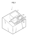
- Fig. 1 is a diagram illustrating the external configuration of an eyeglass-lens processing apparatus in accordance with the invention.
- An eyeglass-frame-shape measuring device 2 is incorporated in an upper right-hand rear portion of a main body 1 of the apparatus.
- the frame-shape measuring device 2 ones that disclosed in USP 5,228,242, 5,333,412, USP5,347,762 (Re. 35,898) and so on, the assignee of which is the same as the present application, can be used.
- a switch panel section 410 having switches for operating the frame-shape measuring device 2 and a display 415 for displaying processing information and the like are disposed in front of the frame-shape measuring device 2.
- reference numeral 420 denotes a switch panel section having various switches for inputting processing conditions and the like and for giving instructions for processing
- numeral 402 denotes an openable window for a processing chamber.
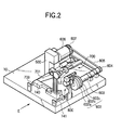
- Fig. 2 is a perspective view illustrating the arrangement of a lens processing section disposed in the casing of the main body 1.
- a carriage section 700 is mounted on a base 10, and a subject lens LE clamped by a pair of lens chuck shafts of a carriage 701 is ground by a group of abrasive wheels 602 attached to a rotating shaft 601.
- the group of abrasive wheels 602 include a rough abrasive wheel 602a for plastic lenses, a finish abrasive wheel 602b having processing surfaces for beveling processing and flat processing, and a polish abrasive wheel 602c having processing surfaces for beveling processing and flat processing.
- the rotating shaft 601 is rotatably attached to the base 10 by a spindle 603.
- a pulley 604 is attached to an end of the rotating shaft 601, and is linked through a belt 605 to a pulley 607 which is attached to a rotating shaft of an abrasive-wheel rotating motor 606.
- a lens-shape measuring section 500 is provided in the rear of the carriage 701. Further, a chamfering and grooving mechanism section 800 is provided in the front side.
- Fig. 3 is a schematic diagram of essential portions of the carriage section 700
- Fig. 4 is a view, taken from the direction of arrow E in Fig. 2, of the carriage section 700.
- the carriage 701 is capable of rotating the lens LE while chucking it with two lens chuck shafts (lens rotating shafts) 702L and 702R, and is rotatably slidable with respect to a carriage shaft 703 that is fixed to the base 10 and that extends in parallel to the abrasive-wheel rotating shaft 601.
- a description will be given of a lens chuck mechanism anda lens rotating mechanism as well as anX-axis moving mechanism and a Y-axis moving mechanism of the carriage 701 by assuming that the direction in which the carriage 701 is moved in parallel to the abrasive-wheel rotating shaft 601 is the X axis, and the direction for changing the axis-to-axis distance between the chuck shafts (702L, 702R) and the abrasive-wheel rotating shaft 601 by the rotation of the carriage 701 is the Y axis.
- the chuck shaft 702L and the chuck shaft 702R are rotatably held coaxially by a left arm 701L and a right arm 701R, respectively, of the carriage 701.
- a chucking motor 710 is fixed to the center of the upper surface of the right arm 701R, and the rotation of a pulley 711 attached to a rotating shaft of the motor 710 rotates a feed screw 713, which is rotatably held inside the right arm 701R, by means of a belt 712.
- a feed nut 714 is moved in the axial direction by the rotation of the feed screw 713.
- the chuck shaft 702R connected to the feed nut 714 can be moved in the axial direction, so that the lens LE is clamped by the chuck shafts 702L and 702R.
- a rotatable block 720 for attaching a motor which is rotatable about the axis of the chuck shaft 702L, is attached to a left-side end portion of the left arm 701L, and the chuck shaft 702L is passed through the block 720, a gear 721 being secured to the left end of the chuck shaft 702L.
- a pulse motor 722 for lens rotation is fixed to the block 720, and as the motor 722 rotates the gear 721 through a gear 724, the rotation of the motor 720 is transmitted to the chuck shaft 702L.
- a pulley 726 is attached to the chuck shaft 702L inside the left arm 701L.
- the pulley 726 is linked by means of a timing belt 731a to a pulley 703a secured to a left end of a rotating shaft 728, which is held rotatably in the rear of the carriage 701. Further, a pulley 703b secured to a right end of the rotating shaft 728 is linked by means of a timing belt 731b to a pulley 733 which is attached to the chuck shaft 702R in such a manner as to be slidable in the axial direction of the chuck shaft 702R inside the right arm 701R. By virtue of this arrangement, the chuck shaft 702L and the chuck shaft 702R are rotated synchronously.
- the carriage shaft 703 is provided with a movable arm 740 which is slidable in its axial direction so that the arm 740 is movable in the X-axis direction (in the axial direction of the shaft 703) together with the carriage 701. Further, the arm 740 at its front portion is slidable on and along a guide shaft 741 that is secured to the base 10 in a parallel positional relation to the shaft 703.
- a rack 743 extending in parallel to the shaft 703 is attached to a rear portion of the arm 740, and this rack 743 meshes with a pinion 746 attached to a rotating shaft of a motor 745 for moving the carriage in the X-axis direction, the motor 745 being secured to the base 10.
- the motor 745 is able to move the carriage 701 together with the arm 740 in the axial direction of the shaft 703 (in the X-axis direction).
- a swingable block 750 is attached to the arm 740 in such a manner as to be rotatable about the axis La which is in alignment with the rotational center of the abrasive wheels 602.
- the distance from the center of the shaft 703 to the axis La and the distance from the center of the shaft 703 to the rotational center of the chuck shaft (702L, 702R) are set to be identical.
- a Y-axis moving motor 751 is attached to the swingable block 750, and the rotation of the motor 751 is transmitted by means of a pulley 752 and a belt 753 to a female screw 755 held rotatably in the swingable block 750.
- a feed screw 756 is inserted in a threaded portion of the female screw 755 in mesh therewith, and the feed screw 756 is moved vertically by the rotation of the female screw 755.
- a guide block 760 which abuts against a lower end surface of the motor-attaching block 720 is fixed to an upper end of the feed screw 756, and the guide block 760 moves along two guide shafts 758a and 758b implanted on the swingable block 750. Accordingly, as the guide block 760 is vertically moved together with the feed screw 756 by the rotation of the motor 751, it is possible to change the vertical position of the block 720 abutting against the guide block 760.
- the vertical position of the carriage 701 attached to the block 720 can be also changed (namely, the carriage 701 rotates about the shaft 703 to change the axis-to-axis distance between the chuck shafts (702L, 702R) and the abrasive-wheel rotating shaft 601).
- a spring 762 is stretched between the left arm 701L and the arm 740, so that the carriage 701 is constantly urged downward to impart processing pressure onto the lens LE.
- the downward urging force acts on the carriage 701
- the downward movement of the carriage 701 is restricted such that the carriage 701 can only be lowered down to the position in which the block 720 abuts against the guide block 760.
- a sensor 764 for detecting an end of processing is attached to the block 720, and the sensor 764 detects the end of processing (ground state) by detecting the position of a sensor plate 765 attached to the guide block 760.
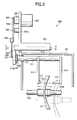
- Fig. 5 is a top view of the lens-shape measuring section
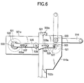
- Fig. 6 is a left side elevational view of Fig. 5
- Fig. 7 is a view illustrating essential portions of the right side surface shown in Fig. 5.
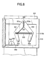
- Fig. 8 is a cross-sectional view taken along line F - F in Fig. 5.
- a supporting block 501 is provided uprightly on the base 10.
- a sliding base 510 is held on the supporting block 501 in such a manner as to be slidable in the left-and-right direction (in a direction parallel to the chuck shafts) by means of a pair of upper and lower guide rail portions 502a and 502b juxtaposed vertically.
- a forwardly extending side plate 510a is formed integrally at a left end of the sliding base 510, and a shaft 511 having a parallel positional relation to the chuck shafts 702L and 702R is rotatably attached to the side plate 510a.
- a feeler arm 514 having a feeler 515 for measuring the lens rear surface is secured to a right end portion of the shaft 511, while a feeler arm 516 having a feeler 517 for measuring the lens front surface is secured to the shaft 511 at a position close to its center.
- Both the feeler 515 and the feeler 517 have a hollow cylindrical shape, a distal end portion of each of the feelers is obliquely cut as shown in Fig. 5, and the obliquely cut tip comes into contact with the rear surface or front surface of the lens LE.
- Contact points of the feeler 515 and the feeler 517 are opposed to each other, and the interval therebetween is arranged to be constant.
- the axis Lb connecting the contact point of the feeler 515 and the contact point of the feeler 517 is in a predetermined parallel positional relation to the axis of the chuck shafts (702L, 702R) in the state of measurement shown in Fig. 5.
- the feeler 515 has a slightly longer hollow cylindrical portion, and measurement is effected by causing its side surface to abut against an edge surface of the lens LE during the measurement of the outside diameter of the lens LE.
- a small gear 520 is fixed to a proximal portion of the shaft 511, and a large gear 521 which is rotatably provided on the side plate 510a is in mesh with the small gear 520.
- a spring 523 is stretched between the large gear 521 and a lower portion of the side plate 510a, so that the large gear 521 is constantly pulled in the direction of rotating clockwise in Fig. 7 by the spring 523. Namely, the arms 514 and 516 are urged so as to rotate downward by means of the small gear 520.
- a slot 503 is formed in the side plate 510a, and a pin 527 which is eccentrically secured to the large gear 521 is passed through the slot 503.
- a first moving plate 528 for rotating the large gear 521 is attached to the pin 527.
- An elongated hole 528a is formed substantially in the center of the first moving plate 528, and a fixed pin 529 secured to the side plate 510a is engaged in the elongated hole 528a.
- a motor 531 for arm rotation is attached to a rear plate 501a extending in the rear of the supporting block 501, and an eccentric pin 533 at a position eccentric from a rotating shaft of the motor 531 is attached to a rotating member 532 provided on a rotating shaft of the motor 531.
- a second moving plate 535 for moving the first moving plate 528 in the back-and-forth direction (in the left-and-right direction in Fig. 6) is attached to the eccentric pin 533.
- An elongated hole 535a is formed substantially in the center of the second moving plate 535, and a fixed pin 537 which is fixed to the rear plate 501a is engaged in the elongated hole 535a.
- a roller 538 is rotatably attached to an end portion of the second moving plate 535.
- the second moving plate 535 moves forward (rightward in Fig. 6) by being guided by the fixed pin 537 and the elongated hole 535a. Since the roller 538 abuts against the end face of the first moving plate 528, the roller 538 moves the first moving plate 528 in the forward direction as well owing to the movement of the second moving plate 535. As a result of this movement, the first moving plate 528 rotates the large gear 521 by means of the pin 527. The rotation of the large gear 521, in turn, causes the feeler arms 514 and 516 attached to the shaft 511 to retreat to an upright state.
- the driving by the motor 531 to this retreated position is determined as an unillustrated micro switch detects the rotated position of the rotating member 532.
- the motor 531 is reversely rotated, the second moving plate 535 is pulled back, the large gear 521 is rotated by being pulled by the spring 523, and the feeler arms 514 and 516 are inclined toward the front side.
- the rotation of the large gear 521 is limited as the pin 527 comes into contact with an end surface of the slot 503 formed in the side plate 510a, thereby determining the measurement positions of the feeler arms 514 and 516.
- the rotation of the feeler arms 514 and 516 up to this measurement positions is detected as the position of a sensor plate 525 attached to the large gear 521 is detected by a sensor 524 attached to the side plate 510a, as shown in Fig. 7.
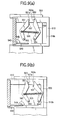
- Fig. 9 is a diagram illustrating the state of left-and-right movement.
- An opening 510b is formed in the sliding base 510, and a rack 540 is provided at a lower end of the opening 510b.
- the rack 540 meshes with a pinion 543 of an encoder 542 fixed to the supporting block 501, and the encoder 542 detects the direction of the left-and-right movement and the amount of movement of the sliding base 510.
- a chevron-shaped driving plate 551 and an inverse chevron-shaped driving plate 553 are attached to a wall surface of the supporting block 501, which is exposed through the opening 510b in the sliding base 510, in such a manner as to be rotatable about a shaft 552 and a shaft 554, respectively.
- a spring 555 having urging forces in the directions in which the driving plate 551 and the driving plate 553 approach each other is stretched between the two driving plates 551 and 553.
- a limiting pin 557 is embedded in the wall surface of the supporting block 501, and when an external force is not acting upon the sliding base 510, both an upper end face 551a of the driving plate 551 and an upper end face 553a of the driving plate 553 are in a state of abutting against the limiting pin 557, and this limiting pin 557 serves as an origin of the left- and rightward movement.
- a guide pin 560 is secured to an upper portion of the sliding base 510 at a position between the upper end face 551a of the driving plate 551 and the upper end face 553a of the driving plate 553.
- the guide pin 560 abuts against the upper end face 553a of the driving plate 553, causing the driving plate 553 to be tilted rightward.
- the sliding base 510 is urged in the direction of being returned to the origin of left- and rightward movement (in the leftward direction) by the spring 555.
- reference numeral 50 denotes a waterproof cover, and only the shaft 511, the feeler arms 514 and 516, and the feelers 515 and 517 are exposed in the waterproof cover 50.
- Numeral 51 denotes a sealant for sealing the gap between the waterproof cover 50 and the shaft 511.
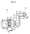
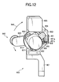
- Fig. 10 is a front elevational view of the chamfering and grooving mechanism section 800; Fig. 11 is a top view; and Fig. 12 is a left side elevational view.
- a fixed plate 802 for attaching the various members is fixed to a supporting block 801 fixed to the base 10.
- a pulse motor 805 for rotating an arm 820 (which will be described later) to move an abrasive wheel section 840 to a processing position and a retreated position is fixed on an upper left-hand side of the fixed plate 802 by four column spacers 806.
- a holding member 811 for rotatably holding an arm rotating member 810 is attached to a central portion of the fixed plate 802, and a large gear 813 is secured to the arm rotating member 810 extending to the left-hand side of the fixed plate 802.
- a gear 807 is attached to a rotating shaft of the motor 805, and the rotation of the gear 807 by the motor 805 is transmitted to the large gear 813 through an idler gear 815, thereby rotating the arm 820 attached to the arm rotating member 810.
- an abrasive-wheel rotating motor 821 is secured to a rear (left-hand side in Fig. 10) of the large gear 813, and the motor 821 rotates together with the large gear 813.
- a rotating shaft of the motor 821 is connected to a shaft 823 which is rotatably held inside the arm rotating member 810, and a pulley 824 is attached to the other end of the shaft 823 extending to the interior of the arm 820.
- a holding member 831 for rotatably holding an abrasive-wheel rotating shaft 830 is attached to a distal end of the arm 820, and a pulley 832 is attached to a left end (left-hand side in Fig. 11) of the abrasive-wheel rotating shaft 830.
- the pulley 832 is connected to the pulley 824 by a belt 835, so that the rotation of the motor 821 is transmitted to the abrasive-wheel rotating shaft 830.
- the abrasive wheel section 840 for grinding and processing the periphery of the lens LE is mounted on a right end of the abrasive-wheel rotating shaft 830.
- the abrasive wheel section 840 is so constructed that a chamfering abrasive wheel 840a for a lens rear surface, a chamfering abrasive wheel 840b for a lens front surface, and a grooving abrasive wheel 840c provided between the two chamfering abrasive wheels 840a and 840b are integrally formed.
- the diameter of the grooving abrasive wheel 840c is about 30 mm, and the chamfering abrasive wheels 840a and 840b on both sides have processing slanting surfaces such that their diameters become gradually smaller toward their outward sides with the grooving abrasive wheel 840c as the center. (The diameter of the grooving abrasive wheel 840c is larger than the outmost diameter of each of the chamfering abrasive wheels 840a and 840b.)
- the abrasive-wheel rotating shaft 830 is disposed in such a manner as to be inclined about 8 degrees with respect to the axial direction of the chuck shafts 702L and 702R, so that the groove can be easily formed along the lens curve by the grooving abrasive wheel 840c.
- the slanting surface of the chamfering abrasive wheel 840a and the slanting surface of the chamfering abrasive wheel 840b are so designed that the chamfering angles for the edge corners of the lens LE chucked by the chuck shafts 702L and 702R are respectively set to 55 degrees and 40 degrees.
- a block 850 is attached to this side on the left-hand side (this side on the left-hand side in Fig. 10) of the fixed plate 802, and a ball plunger 851 having a spring 851a is provided inside the block 850. Further, a limiting plate 853 which is brought into contact with a ball 851b of the ball plunger 851 is fixed to the large gear 813. At the time of starting the grooving or chamfering, the arm 820 is rotated together with the large gear 813 by the rotation of the motor 805, so that the abrasive wheel section 840 is placed at the processing position shown in Fig. 12. At this time, the limiting plate 853 is brought to a position for abutment against the ball 851b.
- a sensor 855 for detecting the origin of the processing position is fixed below the block 850.
- the sensor 855 detects the light-shielded state of a sensor plate 856 attached to the large gear 813 so as to detect the origin of the processing position of the abrasive wheel section 840, i.e., the position where the limiting plate 853 abuts against the ball 851b without application of the urging force due to the ball plunger 851.
- This information on the origin of the processing position is used during calibration for defining the distance between the abrasive wheel section 840 and the chuck shafts 702R and 702L.
- a sensor 858 for detecting the retreated position is fixed on an upper side of the block 850. As the sensor 858 detects a sensor plate 859 attached to the large gear 813, the sensor 858 detects the retreated position of the abrasive wheel section 840 which is rotated together with the arm 820 in the direction of arrow 846.
- the retreatedposition of the abrasive wheel section 840 is set at a position offset rightwardly from a vertical direction in Fig. 12.
- the groove depth in groove processing is changed such that, with the vertical (Y-axis) movement of the carriage 701, the lens LE is moved with respect to the grooving abrasive wheel 840c placed at the processing position.
- the groove width is changed such that, with the horizontal (X-axis) movement of the carriage 701, the lens LE is moved with respect to the grooving abrasive wheel 840c.
- the target lens shape data (frame shape data) on an eyeglass frame is inputted.
- the target lens shape data can be obtained by measuring, by means of a frame shape measuring device 2, the shape of the dummy lens or the template which has been attached to the eyeglass frame F.
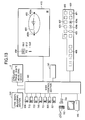
- the target lens shape data obtained by the frame shape measuring device 2 is inputted to a data memory 161 by pressing a switch 421. As shown in Fig. 13, the target lens shape figure 450 based on the target lens shape data is displayed on a display 415, thus making it ready to input processing conditions and layout conditions.
- a processor inputs layout data such as a FPD value, a PD value, and a height of optical center by the operation switches on a switch panel section 420.
- a processing type change mode is selected by a mode switch 423 to input the data for changing the processing type (kind) partially for the lens LE periphery.
- This operation is performed as follows.
- the rotating cursor 451 displayed within the target lens shape figure 450 is rotated and moved to the first point of the range where the processing type (grooving width, depth) is to be changed.
- the point is determined by an ENT switch 426.
- the mark 452a of the point determination is displayed on the profile line of the target lens shape figure 450.
- the rotating cursor 451 is rotated up to the second point of the range where the metal frame portion 100 is to be fitted in the groove.
- the point is determined by the ENT switch 426.
- a mark 452b is displayed at the determined second point, and the interval between the first point and the second point to which the rotating cursor 451 has been moved therefrom flashes on and off.
- a forced grooving mode is selected by the mode switch 423, and then determined by the ENT switch 426.
- This determination by the ENT switch 426 causes the remaining interval (the range where the NYROL string is to be fitted in the groove) to flash on and off.
- the forced grooving mode is selected by the mode switch 423, and determined by the ENT switch 426.
- the ranges where the grooving depth and width are to be partially changed can be inputted.
- the range on the upper side of the marks 452a and 452b will be referred to as a first grooving range, and the range on the lower side as a second grooving range.
- a third point is determined after the determination of the second point, and the same operation is repeated.
- the lens LE is held by two chuck shafts 702L, 702R. Thereafter, when a start switch 428 is pressed to operate the apparatus, the lens shape measuring section 500 is driven to execute a lens LE shape measurement in accordance with the target lens shape data.
- the main control section 160 rotates the lens LE with a feeler 517 abutting against the lens front-side refracting surface, and also vertically moves the carriage 701 based on the target lens shape data.
- the feeler 517 is moved in the horizontal direction along the shape of the lens front-side refracting surface. The amount of this movement is detected by an encoder 542, thus measuring the shape of the front-side refracting surface of the lens LE.
- the shape of the rear-side refracting surface of the lens LE is measured by causing a feeler 515 to abut against the lens surface so as similarly to detect the amount of movement of the feeler 515.
- the main control section 160 based on the edge position information obtained by the lens shape measurement, makes a calculation for the processing data (the data on a groove path) on each range in accordance with a predetermined program.
- the groove path is obtained, for instance, such that the edge thickness of the lens LE is divided at a predetermined ratio.
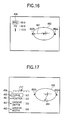
- Fig. 15 is an example of the simulation screen.
- the approximate curve value obtained from the groove path data is displayed in a "curve" item 460.
- the value can be changed by adjusting the switch 424a or 424b for increase or decrease. in numeric value.
- the curve value is changed, the groove path data approximate to the curve value is calculated again.
- the curve value is used as a practical representation of the lens curve on an eyeglass lens.
- a "position" item 461 is the item where the amount of offset by which the groove path is moved in parallel toward the lens front side or rear side is inputted.
- the values of grooving depth and width to be partially changed are inputted as follows.
- the rotating cursor 451 is rotated and positioned in the first grooving range on the target lens shape figure 450, the values of grooving depth and width in this range are made changeable.
- the cursor 458 is put on a "groove depth" item 462 or a "groove width” 463, the value in the item is changed to increase or decrease with the switch 424a or 424b.
- the display of the right-side numeric value in each item indicates the current value, and the value to be changed is displayed as reversed indication.
- the groove depth and the groove width in the first grooving range are set to 0.6 mm and 0.6 mm, respectively.
- the values of grooving depth and width in this range are made changeable.
- the respective values displayed as reversed indication are changed by putting the cursor 458 on the "groove depth” item 462 and the "groove width” item 463.
- the display of the right-side numeric value in each item indicates the current value.
- the groove depth and the groove width in the second grooving range are set to 0.8 mm and 0.8 mm, respectively.
- each boundary between the first and second grooving ranges is influenced by the diameter of the grooving abrasive wheel 840c.
- the groove path is calculated such that a depth of 0.8 mm of the second grooving range, i.e. a larger depth, is secured at each boundary.
- the rotating cursor 451 displayed within the target lens shape figure 450 is rotated in the same way as described above to specify the edge position, the estimated edge sectional form to be obtained as a consequence of the processing is displayed in the left upper portion of the screen. Accordingly, a bevel sectional form or a groove sectional form can be confirmed over the entire periphery.
- processing is executed by pressing the start switch 428 again.
- the main control section 160 moves the carriage 701 such that the lens LE is placed above the rough abrasive wheel 602a, and vertically moves the carriage 701 to perform rough processing in accordance with the rough processing data preliminarily obtained on the basis of the target lens shape data and the layout data.
- the lens LE is moved to the planar portion of the finish abrasive wheel 602b, and the plane finishing processing over the entire periphery is performed in accordance with preliminarily obtained plane finishing processing data.
- the groove processing is performed by the grooving abrasive wheel 840c in the chamfering and grooving mechanism section 800.
- the main control section 160 drives such that the abrasive wheel section 840 placed at the retreated position comes to the processing position, and then positions the lens LE on the grooving abrasive wheel 840c.
- the main control section 160 controls the movement of the carriage 701 based on the groove path data which are set at 0.6 mm in groove depth and 0.6 mm in groove width in the first grooving range.
- the abrasive wheel width of the grooving abrasive wheel 840c in the embodiment is set to 0.6 mm, which is to be the minimum groove width.
- the main control section 160 controls the movement of the carriage 701 so that the lens LE is processed to have a groove width of 0.6 mm by one revolution of the lens LE. Thereafter, in order to further process the lens LE to add the remaining width of 0.2 mm only in this second grooving range, the main control section 160 controls, while rotating the lens LE, the movement of the carriage 701 in the horizontal direction (in the axial direction of the chuck shafts 702L, 702R) based on the groove path data. Also, in order to have a groove depth of 0.8 mm in this second grooving range, the main control section 160 controls the vertical movement of the carriage 701. Thus, the processing which is partially different in grooving width and depth is performed with respect to the periphery of the lens LE.
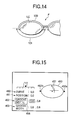
- the eyeglass frame F shown in Fig. 14 is designed such that a bevel groove is formed in the rim portion 100, i.e. an upper part of the frame F, and the lens LE is held by the NYROL string in the lower portion (the range 101 indicated by an arrow in the drawing) below the rim portion 100.
- the target lens shape figure 450 is displayed on the display 415, thus making it ready to input processing conditions and layout conditions.
- a processing type change mode is selected by the mode switch 423, and, in the same way as described above, the divided portions, i.e. the bevel processing range and the grooving range, are determined by the point specification using the rotation of the rotating cursor 451 and the ENT switch 426.
- the interval between the first point and the second point to which the rotating cursor 451 has been moved therefrom flashes on and off.
- a forced beveling mode is selected by the mode switch 423, and then determined by the ENT switch 426.
- This determination by the ENT switch 426 causes the remaining interval to flash on and off.
- the forced grooving mode is selected by the mode switch 423, and determined by the ENT switch 426.
- the inflection points of the beveling portion and grooving portion can be obtained.
- the data on the points with which the processing ranges are defined are automatically inputted based on these inflection points.
- the points with which the processing ranges are defined are determined in view of the shape of the joint between the beveling portion and the grooving portion on the basis of the diameter of the finishing abrasive wheel 602b.
- the start switch 428 is pressed, thereby executing a lens shape measurement.
- the main control section 160 calculates for the bevel path data and groove path data which are the processing data on the respective ranges.
- the bevel path data is preferably corrected such that the bevel shoulder portion to be formed on the periphery of the lens LE and the plane finishing portion to be subjected to groove processing are smoothly joined.
- the screen of the display 415 is switched to the simulation screen as shown in Fig. 17.
- the values in the "curve" item 460 etc. are changed in the same way as described above to obtain desired bevel path and groove path.
- each of the grooving depth and width can be changed by putting the cursor 458 on the item 462, 463 and then increasing or decreasing the value in the item 462, 463 with the switch 424a or 424b.
- the processing data on each range is calculated again.
- Processing is executed by pressing the start switch 428 again.
- the main control section 160 moves the carriage 701 such that the lens LE is placed above the rough abrasive wheel 602a, and vertically moves the carriage 701 to perform rough processing in accordance with the rough processing data based on the target lens shape data and the layout data.
- the rough processing data is calculated, taking into account the grinding margin for bevel finishing processing and the grinding margin for the plane finishing processing prior to grooving.
- the lens LE is moved to the planar portion of the finish abrasive wheel 602b to perform plane finishing processing on the peripheral portion where the groove processing is to be performed.
- This plane finishing processing is performed in accordance with the aforesaid groove processing range data.
- the main control section 160 drives the motor 722 to rotate the lens LE held by the two chuck shafts 702L, 702R, and also performs the plane finishing processing while, in the range of a radius vector angle where the groove processing is to be performed, pressing the lens LE against the planar portion of the finish abrasive wheel 602b by vertically moving the carriage 701.
- the carriage 701 is moved such that the lens LE escapes from the finish abrasive wheel 602b.
- the lens LE is moved to the bevel groove portion of the finish abrasive wheel 602b to perform bevel finishing processing.
- the bevel finishing processing is performed with the lens LE pressed against the bevel groove portion of the finish abrasive wheel 602b.
- the chamfering and grooving mechanism section 800 is driven to proceed to the groove processing.
- the main control section 160 raises the carriage 701, and then rotates the motor 805 by a predetermined number of pulses so that the abrasive wheel 840 placed at the retreated position comes to the processing position.
- the carriage 701 is moved vertically and in the axial direction, whereby the lens LE is positioned on the grooving abrasive wheel 840c, thus performing the processing by controlling the movement of the carriage 701 based on the data on the groove path in the aforesaid groove processing range.
- the processing with respect to the periphery of the lens LE can also be executed with the plane finishing processing partially combined.
- the processing range is specified by the rotating cursor 451 on the layout data input screen shown in Fig 13, 16, and the plane finishing processing is selected by the mode switch 423, thereby inputting the data for changing the processing range and the processing type.
- the apparatus in the embodiment is provided with a polish abrasive wheel 602c.
- the apparatus can also perform partial polish processing on the lens periphery after the finish processing.
- a polish range change mode is selected by a polish switch 427 on the switch panel section 420 with the layout screen shown in Fig. 13 displayed, thus changing to the mode in which the polish processing can be partially specified.
- the rotating cursor 451 is rotated, and two points of the range to be subjected to the polish processing are specified on the target lens shape figure 450. The points are determined by the ENT switch 426, thereby inputting the data on the range where the polish processing is to be performed.
- the main control section 160 moves the lens LE to the polish abrasive wheel 602c after the bevel finishing processing and the plane finishing processing.
- the polish finishing processing is performed by the bevel groove portion of the polish finishing abrasive wheel 602c based on the polish finishing range data.
- the polish finishing processing is performed by the planar portion of the polish finishing abrasive wheel 602c based on the polish finishing range data.
- the target lens shape data is obtained by the measurement by means of the frame shape measuring device 2.
- the target lens shape data is known beforehand at an eyeglass frame maker, the same data is inputted for use.
- the two-dimensional code tag 162 including the target lens shape data is attached to the eyeglass frame F.
- the data is inputted by reading it by the code reader 163 coupled to the main control section 160 (see Fig. 13).
- an IC chip or an IC card can also be used as a storage medium.
- the target lens shape data obtained from the eyeglass frame maker is made to correspond with the model number etc. of an eyeglass frame, and shred in the database of an external computer 165.
- the target lens shape data is retrieved by specifying the model number etc. of the eyeglass frame, and inputted to the processing apparatus body side. Furthermore, there can also be adopted a method of using the data downloaded into the external computer 165 compled to the database of the frame maker via a communication network such as internet etc.
- the data includes the range where the processing is to be partially changed (the data on the points where the aforesaid first and second grooving ranges are to be changed, and the data on the points where the beveling and grooving are to be changed), then the need to input by an operator is eliminated. Further, in case of the groove processing, the data of the groove depth and width in each range can be included. Such design data on an eyeglass frame are used intactly, thereby improving the precision of a processed shape.
- the disk-like grooving abrasive wheel is used as a grinding tool for groove processing.
- the present invention is also applicable to a case that the groove processing is executed using an end mill.
- the (kind of) processing to be performed over the lens periphery can be partially changed, thus enabling expansion of the degree of freedom with respect to the design of a frame and a lens.
Landscapes
- Engineering & Computer Science (AREA)
- Mechanical Engineering (AREA)
- Chemical & Material Sciences (AREA)
- Ceramic Engineering (AREA)
- Inorganic Chemistry (AREA)
- Grinding And Polishing Of Tertiary Curved Surfaces And Surfaces With Complex Shapes (AREA)
Abstract
Description
Claims (8)
- An eyeglass lens processing apparatus for processing a periphery of an eyeglass lens, comprising:detecting means for detecting an edge position of the lens based on inputted target lens shape data and layout data;processing means, having at least one grinding tool, for processing the lens by relatively moving the lens with respect to the grinding tool, the at least one grinding tool being adapted to execute at least two types of processing including:a plane finish processing in which the lens periphery is finished flatly;a bevel finish processing in which a bevel is formed to the lens periphery;a plane polish processing in which the lens periphery is finished into a flat polished surface;a bevel polish processing in which the lens periphery is polished with a bevel formed thereto;a first groove processing in which a first groove is formed to the lens periphery; anda second groove processing in which a second groove different in at least one of groove width and groove depth from the first groove is formed to the lens periphery;input means for inputting data on ranges of the lens periphery and data on respective processing types to partially change the processing types to be executed on the lens periphery;computing means for obtaining processing data for the respective ranges, different in processing type, based on data on edge position and data on processing type corresponding respectively to the ranges; andcontrol means for controlling the processing means based on the obtained processing data.
- The apparatus of claim 1, wherein:the data on ranges of the lens periphery include range data designed at an eyeglass frame maker and stored in a storage medium together with the target lens shape data; andthe input means reads the range data together with the target lens shape data from the storage medium and inputs these data.
- The apparatus of claim 1 or 2, wherein:the data on ranges of the lens periphery include range data designed at an eyeglass frame maker together with the target lens shape data; andthe input means inputs the range data and the target lens shape data via a communications net work.
- The apparatus of any one of claims 1 to 3, wherein the input means includes:display means for displaying a target lens shape figure based on the inputted target lens shape data; andspecifying means for specifying the ranges on the displayed target lens shape figure.
- The apparatus of any one of claims 1 to 4, wherein the input means includes selection means for selecting, from stored processing types, a desired processing type for each of the ranges.
- The apparatus of any one of claims 1 to 5, wherein the input means inputs data on groove width and groove depth of the first groove and data on groove width and groove depth of the second groove when the first groove processing and the second groove processing are inputted as the processing types.
- The apparatus of any one of claims 1 to 6, further comprising:measuring means for measuring an eyeglass frame, a template or a dummy lens, and inputting measured configuration data as the target lens shape data.
- The apparatus of any one of claims 1 to 7, further comprising:layout input means for inputting the layout data for layout of the lens with respect to the inputted target lens shape data.
Applications Claiming Priority (2)
| Application Number | Priority Date | Filing Date | Title |
|---|---|---|---|
| JP2000184586A JP3961196B2 (en) | 2000-06-15 | 2000-06-15 | Eyeglass lens processing equipment |
| JP2000184586 | 2001-06-15 |
Publications (2)
| Publication Number | Publication Date |
|---|---|
| EP1266722A1 true EP1266722A1 (en) | 2002-12-18 |
| EP1266722B1 EP1266722B1 (en) | 2009-03-04 |
Family
ID=18685005
Family Applications (1)
| Application Number | Title | Priority Date | Filing Date |
|---|---|---|---|
| EP01114490A Expired - Lifetime EP1266722B1 (en) | 2000-06-15 | 2001-06-15 | Eyeglass lens processing apparatus |
Country Status (5)
| Country | Link |
|---|---|
| US (1) | US6702653B2 (en) |
| EP (1) | EP1266722B1 (en) |
| JP (1) | JP3961196B2 (en) |
| DE (1) | DE60137836D1 (en) |
| ES (1) | ES2322021T3 (en) |
Cited By (1)
| Publication number | Priority date | Publication date | Assignee | Title |
|---|---|---|---|---|
| EP2425926A1 (en) | 2010-09-07 | 2012-03-07 | Essilor International (Compagnie Générale D'Optique) | Method for trimming an ophthalmic lens |
Families Citing this family (27)
| Publication number | Priority date | Publication date | Assignee | Title |
|---|---|---|---|---|
| JP4562343B2 (en) * | 2002-04-08 | 2010-10-13 | Hoya株式会社 | EX-type multifocal lens bevel locus determination method and EX-type multifocal lens processing apparatus |
| JP2003300158A (en) * | 2002-04-08 | 2003-10-21 | Hoya Corp | Lens processing equipment |
| JP2003340698A (en) * | 2002-05-30 | 2003-12-02 | Hoya Corp | Lens processing apparatus and lens processing method |
| JP2004058203A (en) * | 2002-07-29 | 2004-02-26 | Hoya Corp | Lens working method, lens working device, and lens |
| JP4707965B2 (en) * | 2004-04-30 | 2011-06-22 | 株式会社ニデック | Spectacle lens peripheral processing method, spectacle lens peripheral processing system, and spectacle frame shape measuring apparatus |
| WO2006003939A1 (en) * | 2004-06-30 | 2006-01-12 | Hoya Corporation | Method of manufacturing spectacle lens |
| JP4551162B2 (en) * | 2004-08-31 | 2010-09-22 | 株式会社ニデック | Eyeglass lens processing equipment |
| JP4774203B2 (en) * | 2004-10-01 | 2011-09-14 | 株式会社ニデック | Eyeglass lens processing equipment |
| JP2006189472A (en) * | 2004-12-28 | 2006-07-20 | Nidek Co Ltd | Spectacle lens processing device |
| JP4772342B2 (en) * | 2005-02-28 | 2011-09-14 | 株式会社ニデック | Eyeglass lens processing equipment |
| JP4873878B2 (en) * | 2005-03-31 | 2012-02-08 | 株式会社ニデック | Eyeglass lens peripheral processing equipment |
| DE102005015449B3 (en) * | 2005-04-04 | 2006-11-16 | Weco Optik Gmbh | Spectacle lens edging machine |
| JP4446934B2 (en) * | 2005-06-30 | 2010-04-07 | 株式会社ニデック | Eyeglass lens processing equipment |
| JP2007181889A (en) * | 2006-01-05 | 2007-07-19 | Nidek Co Ltd | Eyeglass lens processing system |
| JP2007203423A (en) * | 2006-02-03 | 2007-08-16 | Nidek Co Ltd | Spectacle lens peripheral fringe working device |
| JP5028025B2 (en) | 2006-05-02 | 2012-09-19 | 株式会社ニデック | Eyeglass lens peripheral processing equipment |
| US7848843B2 (en) | 2007-03-28 | 2010-12-07 | Nidek Co., Ltd. | Eyeglass lens processing apparatus and lens fixing cup |
| JP5073345B2 (en) * | 2007-03-30 | 2012-11-14 | 株式会社ニデック | Eyeglass lens processing equipment |
| DE102007042667A1 (en) * | 2007-09-10 | 2009-03-12 | Schneider Gmbh & Co. Kg | Polishing machine for lenses and method for polishing a lens with a processing machine |
| JP5469476B2 (en) * | 2010-02-15 | 2014-04-16 | 株式会社ニデック | Eyeglass lens processing equipment |
| DE102010010338A1 (en) * | 2010-03-04 | 2011-09-08 | Schneider Gmbh & Co. Kg | auto calibration |
| WO2012045411A1 (en) * | 2010-10-04 | 2012-04-12 | Schneider Gmbh & Co. Kg | Apparatus and method for working an optical lens and also an optical lens and a transporting container for optical lenses |
| DE202010008898U1 (en) * | 2010-10-26 | 2010-12-30 | Lukas-Erzett Vereinigte Schleif- Und Fräswerkzeugfabriken Gmbh & Co. Kg | Abrasive blade for arranging on a grinding disc which can be driven in rotation about a rotation axis |
| FR2972382B1 (en) * | 2011-03-10 | 2013-04-26 | Briot Int | OPTICAL GLASS GRINDING MACHINE AND ASSOCIATED GRINDING METHOD |
| JP6225430B2 (en) * | 2013-02-09 | 2017-11-08 | 株式会社ニデック | Eyeglass lens peripheral processing system and spectacle lens peripheral processing program |
| JP7052196B2 (en) * | 2017-01-31 | 2022-04-12 | 株式会社ニデック | Eyeglass lens processing equipment and processing control program |
| CN116512091B (en) * | 2023-05-26 | 2023-10-20 | 广东宝星新型石材有限公司 | Physical brightening and brightening device for high polymer artificial stone plate |
Citations (5)
| Publication number | Priority date | Publication date | Assignee | Title |
|---|---|---|---|---|
| JPS55157461A (en) * | 1979-05-22 | 1980-12-08 | Seiko Koki Kk | Automatic grooving method of lens edge |
| DE3509534A1 (en) * | 1985-03-16 | 1986-09-25 | Otto 4010 Hilden Helbrecht | Machine for grinding the edges of spectacle lenses |
| DE19738668A1 (en) * | 1997-09-04 | 1999-03-18 | Wernicke & Co Gmbh | Spectacle lens edging machine |
| EP1066918A2 (en) * | 1999-07-07 | 2001-01-10 | Nidek Co., Ltd. | Eyeglass lens processing apparatus |
| JP2001150314A (en) * | 1999-11-25 | 2001-06-05 | Topcon Corp | Eyeglass lens grinding equipment |
Family Cites Families (13)
| Publication number | Priority date | Publication date | Assignee | Title |
|---|---|---|---|---|
| JP2761590B2 (en) | 1989-02-07 | 1998-06-04 | 株式会社ニデック | Eyeglass lens grinding machine |
| JP2845945B2 (en) | 1989-06-07 | 1999-01-13 | 株式会社日立製作所 | Magnetron |
| JP2925685B2 (en) | 1990-08-02 | 1999-07-28 | 株式会社ニデック | Frame shape measuring device |
| JP2918657B2 (en) | 1990-08-09 | 1999-07-12 | 株式会社ニデック | Eyeglass lens grinding machine |
| US5333412A (en) | 1990-08-09 | 1994-08-02 | Nidek Co., Ltd. | Apparatus for and method of obtaining processing information for fitting lenses in eyeglasses frame and eyeglasses grinding machine |
| JP2907974B2 (en) | 1990-08-28 | 1999-06-21 | 株式会社ニデック | Eyeglass frame tracing device |
| JP3011526B2 (en) | 1992-02-04 | 2000-02-21 | 株式会社ニデック | Lens peripheral processing machine and lens peripheral processing method |
| JP3667483B2 (en) | 1997-02-10 | 2005-07-06 | 株式会社ニデック | Lens grinding machine |
| JP4068177B2 (en) | 1997-03-31 | 2008-03-26 | 株式会社ニデック | Lens grinding machine |
| JP3688438B2 (en) * | 1997-06-30 | 2005-08-31 | 株式会社ニデック | Eyeglass lens grinding device |
| JP3730409B2 (en) * | 1998-05-29 | 2006-01-05 | 株式会社ニデック | Eyeglass lens processing equipment |
| JP2000015549A (en) * | 1998-06-30 | 2000-01-18 | Nidek Co Ltd | Eyeglass lens processing equipment |
| JP4068229B2 (en) * | 1998-08-03 | 2008-03-26 | 株式会社ニデック | Eyeglass lens layout device |
-
2000
- 2000-06-15 JP JP2000184586A patent/JP3961196B2/en not_active Expired - Fee Related
-
2001
- 2001-06-15 US US09/880,910 patent/US6702653B2/en not_active Expired - Lifetime
- 2001-06-15 EP EP01114490A patent/EP1266722B1/en not_active Expired - Lifetime
- 2001-06-15 ES ES01114490T patent/ES2322021T3/en not_active Expired - Lifetime
- 2001-06-15 DE DE60137836T patent/DE60137836D1/en not_active Expired - Lifetime
Patent Citations (5)
| Publication number | Priority date | Publication date | Assignee | Title |
|---|---|---|---|---|
| JPS55157461A (en) * | 1979-05-22 | 1980-12-08 | Seiko Koki Kk | Automatic grooving method of lens edge |
| DE3509534A1 (en) * | 1985-03-16 | 1986-09-25 | Otto 4010 Hilden Helbrecht | Machine for grinding the edges of spectacle lenses |
| DE19738668A1 (en) * | 1997-09-04 | 1999-03-18 | Wernicke & Co Gmbh | Spectacle lens edging machine |
| EP1066918A2 (en) * | 1999-07-07 | 2001-01-10 | Nidek Co., Ltd. | Eyeglass lens processing apparatus |
| JP2001150314A (en) * | 1999-11-25 | 2001-06-05 | Topcon Corp | Eyeglass lens grinding equipment |
Non-Patent Citations (2)
| Title |
|---|
| PATENT ABSTRACTS OF JAPAN vol. 005, no. 033 (M - 057) 28 February 1981 (1981-02-28) * |
| PATENT ABSTRACTS OF JAPAN vol. 2000, no. 23 10 February 2001 (2001-02-10) * |
Cited By (3)
| Publication number | Priority date | Publication date | Assignee | Title |
|---|---|---|---|---|
| EP2425926A1 (en) | 2010-09-07 | 2012-03-07 | Essilor International (Compagnie Générale D'Optique) | Method for trimming an ophthalmic lens |
| FR2964336A1 (en) * | 2010-09-07 | 2012-03-09 | Essilor Int | METHOD FOR DISTRESSING AN OPHTHALMIC LENS |
| US8926401B2 (en) | 2010-09-07 | 2015-01-06 | Essilor International (Compagnie Generale D'optique) | Method of shaping an ophthalmic lens |
Also Published As
| Publication number | Publication date |
|---|---|
| EP1266722B1 (en) | 2009-03-04 |
| US20010053659A1 (en) | 2001-12-20 |
| DE60137836D1 (en) | 2009-04-16 |
| JP2001353649A (en) | 2001-12-25 |
| JP3961196B2 (en) | 2007-08-22 |
| ES2322021T3 (en) | 2009-06-16 |
| US6702653B2 (en) | 2004-03-09 |
Similar Documents
| Publication | Publication Date | Title |
|---|---|---|
| EP1266722B1 (en) | Eyeglass lens processing apparatus | |
| JP4162332B2 (en) | Eyeglass lens processing equipment | |
| EP1155775B1 (en) | Eyeglass lens processing apparatus | |
| US6089957A (en) | Method of grinding eyeglass len, and eyeglass lens grinding apparatus | |
| EP1974857B1 (en) | Eyeglass lens processing apparatus | |
| EP2191935B1 (en) | Eyeglass lens processing apparatus for processing periphery of eyeglass lens | |
| EP0839609B1 (en) | Apparatus for grinding eyeglass lenses | |
| JP4772342B2 (en) | Eyeglass lens processing equipment | |
| JP3990104B2 (en) | Lens grinding machine | |
| KR101437160B1 (en) | Glasses lens processing equipment | |
| EP1728589B1 (en) | Eyeglass lens processing apparatus | |
| KR101415449B1 (en) | Setting apparatus for facet processing area and eyeglass lens processing apparatus therewith | |
| EP1366857B1 (en) | Eyeglass lens processing apparatus | |
| JP4431413B2 (en) | Eyeglass lens processing equipment | |
| JPH05111866A (en) | Bevel position display device | |
| JPS60238265A (en) | Chamfering whetstone and beading machine equipped with it | |
| JP3547273B2 (en) | Eyeglass frame shape measuring device and eyeglass frame shape measuring method | |
| JPH07186025A (en) | Lens chamfering device | |
| JP2004237389A (en) | Spectacle lens working device | |
| JPH05269658A (en) | Lens grinding machine | |
| JPH07116948A (en) | Jade machine |
Legal Events
| Date | Code | Title | Description |
|---|---|---|---|
| PUAI | Public reference made under article 153(3) epc to a published international application that has entered the european phase |
Free format text: ORIGINAL CODE: 0009012 |
|
| AK | Designated contracting states |
Kind code of ref document: A1 Designated state(s): AT BE CH CY DE DK ES FI FR GB GR IE IT LI LU MC NL PT SE TR |
|
| AX | Request for extension of the european patent |
Free format text: AL;LT;LV;MK;RO;SI |
|
| 17P | Request for examination filed |
Effective date: 20030423 |
|
| AKX | Designation fees paid |
Designated state(s): DE ES FR GB |
|
| 17Q | First examination report despatched |
Effective date: 20071130 |
|
| GRAP | Despatch of communication of intention to grant a patent |
Free format text: ORIGINAL CODE: EPIDOSNIGR1 |
|
| GRAS | Grant fee paid |
Free format text: ORIGINAL CODE: EPIDOSNIGR3 |
|
| GRAA | (expected) grant |
Free format text: ORIGINAL CODE: 0009210 |
|
| AK | Designated contracting states |
Kind code of ref document: B1 Designated state(s): DE ES FR GB |
|
| REG | Reference to a national code |
Ref country code: GB Ref legal event code: FG4D |
|
| REF | Corresponds to: |
Ref document number: 60137836 Country of ref document: DE Date of ref document: 20090416 Kind code of ref document: P |
|
| REG | Reference to a national code |
Ref country code: ES Ref legal event code: FG2A Ref document number: 2322021 Country of ref document: ES Kind code of ref document: T3 |
|
| PLBE | No opposition filed within time limit |
Free format text: ORIGINAL CODE: 0009261 |
|
| STAA | Information on the status of an ep patent application or granted ep patent |
Free format text: STATUS: NO OPPOSITION FILED WITHIN TIME LIMIT |
|
| 26N | No opposition filed |
Effective date: 20091207 |
|
| PGFP | Annual fee paid to national office [announced via postgrant information from national office to epo] |
Ref country code: GB Payment date: 20120613 Year of fee payment: 12 |
|
| PGFP | Annual fee paid to national office [announced via postgrant information from national office to epo] |
Ref country code: ES Payment date: 20120621 Year of fee payment: 12 |
|
| GBPC | Gb: european patent ceased through non-payment of renewal fee |
Effective date: 20130615 |
|
| PG25 | Lapsed in a contracting state [announced via postgrant information from national office to epo] |
Ref country code: GB Free format text: LAPSE BECAUSE OF NON-PAYMENT OF DUE FEES Effective date: 20130615 |
|
| REG | Reference to a national code |
Ref country code: ES Ref legal event code: FD2A Effective date: 20140707 |
|
| PG25 | Lapsed in a contracting state [announced via postgrant information from national office to epo] |
Ref country code: ES Free format text: LAPSE BECAUSE OF NON-PAYMENT OF DUE FEES Effective date: 20130616 |
|
| REG | Reference to a national code |
Ref country code: FR Ref legal event code: PLFP Year of fee payment: 16 |
|
| REG | Reference to a national code |
Ref country code: FR Ref legal event code: PLFP Year of fee payment: 17 |
|
| REG | Reference to a national code |
Ref country code: FR Ref legal event code: PLFP Year of fee payment: 18 |
|
| PGFP | Annual fee paid to national office [announced via postgrant information from national office to epo] |
Ref country code: FR Payment date: 20200512 Year of fee payment: 20 Ref country code: DE Payment date: 20200602 Year of fee payment: 20 |
|
| REG | Reference to a national code |
Ref country code: DE Ref legal event code: R071 Ref document number: 60137836 Country of ref document: DE |