EP2425926A1 - Method for trimming an ophthalmic lens - Google Patents
Method for trimming an ophthalmic lens Download PDFInfo
- Publication number
- EP2425926A1 EP2425926A1 EP11290347A EP11290347A EP2425926A1 EP 2425926 A1 EP2425926 A1 EP 2425926A1 EP 11290347 A EP11290347 A EP 11290347A EP 11290347 A EP11290347 A EP 11290347A EP 2425926 A1 EP2425926 A1 EP 2425926A1
- Authority
- EP
- European Patent Office
- Prior art keywords
- ophthalmic lens
- contour
- arc
- longitudinal profile
- final
- Prior art date
- Legal status (The legal status is an assumption and is not a legal conclusion. Google has not performed a legal analysis and makes no representation as to the accuracy of the status listed.)
- Granted
Links
- 238000000034 method Methods 0.000 title claims abstract description 29
- 238000009966 trimming Methods 0.000 title claims description 22
- 101150099299 HBQ1 gene Proteins 0.000 claims description 11
- 230000000295 complement effect Effects 0.000 claims description 5
- 238000013519 translation Methods 0.000 description 11
- 239000004677 Nylon Substances 0.000 description 9
- 229920001778 nylon Polymers 0.000 description 9
- 238000003754 machining Methods 0.000 description 5
- 239000011521 glass Substances 0.000 description 4
- 238000005498 polishing Methods 0.000 description 4
- 230000008901 benefit Effects 0.000 description 3
- 230000000903 blocking effect Effects 0.000 description 3
- 238000012937 correction Methods 0.000 description 3
- 210000001331 nose Anatomy 0.000 description 3
- 240000008042 Zea mays Species 0.000 description 2
- 230000006835 compression Effects 0.000 description 2
- 238000007906 compression Methods 0.000 description 2
- 238000005520 cutting process Methods 0.000 description 2
- 238000003384 imaging method Methods 0.000 description 2
- 239000000463 material Substances 0.000 description 2
- 230000002093 peripheral effect Effects 0.000 description 2
- 230000000750 progressive effect Effects 0.000 description 2
- 238000012546 transfer Methods 0.000 description 2
- 230000007704 transition Effects 0.000 description 2
- 230000005355 Hall effect Effects 0.000 description 1
- 238000004891 communication Methods 0.000 description 1
- 238000004519 manufacturing process Methods 0.000 description 1
- 230000003287 optical effect Effects 0.000 description 1
- 238000002360 preparation method Methods 0.000 description 1
- 238000012545 processing Methods 0.000 description 1
- 230000002123 temporal effect Effects 0.000 description 1
Images


Classifications
-
- B—PERFORMING OPERATIONS; TRANSPORTING
- B24—GRINDING; POLISHING
- B24B—MACHINES, DEVICES, OR PROCESSES FOR GRINDING OR POLISHING; DRESSING OR CONDITIONING OF ABRADING SURFACES; FEEDING OF GRINDING, POLISHING, OR LAPPING AGENTS
- B24B9/00—Machines or devices designed for grinding edges or bevels on work or for removing burrs; Accessories therefor
- B24B9/02—Machines or devices designed for grinding edges or bevels on work or for removing burrs; Accessories therefor characterised by a special design with respect to properties of materials specific to articles to be ground
- B24B9/06—Machines or devices designed for grinding edges or bevels on work or for removing burrs; Accessories therefor characterised by a special design with respect to properties of materials specific to articles to be ground of non-metallic inorganic material, e.g. stone, ceramics, porcelain
- B24B9/08—Machines or devices designed for grinding edges or bevels on work or for removing burrs; Accessories therefor characterised by a special design with respect to properties of materials specific to articles to be ground of non-metallic inorganic material, e.g. stone, ceramics, porcelain of glass
- B24B9/14—Machines or devices designed for grinding edges or bevels on work or for removing burrs; Accessories therefor characterised by a special design with respect to properties of materials specific to articles to be ground of non-metallic inorganic material, e.g. stone, ceramics, porcelain of glass of optical work, e.g. lenses, prisms
-
- B—PERFORMING OPERATIONS; TRANSPORTING
- B24—GRINDING; POLISHING
- B24B—MACHINES, DEVICES, OR PROCESSES FOR GRINDING OR POLISHING; DRESSING OR CONDITIONING OF ABRADING SURFACES; FEEDING OF GRINDING, POLISHING, OR LAPPING AGENTS
- B24B51/00—Arrangements for automatic control of a series of individual steps in grinding a workpiece
Definitions
- the present invention relates generally to the preparation of ophthalmic lenses for interlocking in eyeglass frames.
- It relates more particularly to a method of trimming an ophthalmic lens for mounting in a mixed environment of a spectacle frame.
- the technical part of the optician's profession is to mount a pair of corrective ophthalmic lenses on a spectacle frame selected by a wearer.
- the entourage has an arch that fits an upper portion of the lens contour and a nylon thread that runs along the lower portion of the lens contour to hold the lens in contact with the lens. 'arcade.
- the finishing step then generally consists of creasing the slice of the lens to form an interlocking groove that can accommodate not only the nylon yarn, but also a rib provided along the inner face of the yoke.
- EP 1 266 722 a method of trimming a lens ophthalmic wherein the finishing step comprises a first creasing operation of an upper portion of the lens contour, and a second creasing operation of a lower portion of the lens contour with a different depth, providing better support nylon thread.
- spectacle frames are known, each of which has an interruption.
- the finishing step of the lens then comprises a first beveling operation of a major part of the lens contour, and a second operation of grinding the edge of the lens with a cylindrical grinding wheel of revolution, at the level of the interruption of the entourage.
- the finishing step of the lens comprises a first beveling operation of an upper portion of the contour of the lens, followed by a creasing operation of a lower portion of the contour of the lens.
- the present invention provides a method of trimming an ophthalmic lens as defined in claim 1.
- the border between the two finishes is no longer positioned at the end of the first section of the entourage (typically the arcade), but below this first section.
- the discontinuities located at the border between the two parts of the outline of the lens are then hidden under the first section of the entourage, to the benefit of the aesthetics of the pair of glasses.
- the nylon thread can engage directly in the groove, without abutting against the interlocking rib, at advantage of the rigidity of the assembly.
- the present invention relates to a method of trimming an ophthalmic lens for mounting in an environment of a spectacle frame with mixed surrounds.
- Eyeglass frames with mixed surrounds means any frame each surround has an interrupted section or two distinct sections (that is to say two sections equipped with lens attachment means that have different architectures).
- the first two types of spectacle frames are semi-rimmed frames.
- such a semi-rimmed spectacle frame 20 comprises two surrounds 21 each comprising an arch 21A (the first section) which bears against an upper part of the contour of the ophthalmic lens 10 and a nylon thread 21 B (the second section) which runs along a lower part of the contour of this lens in order to maintain it in support against the arch 21A.
- the first type of eyeglass frame comprises, on the inner face of each of its arches 21A, a nesting rib arranged to engage in a groove provided on the edge of the corresponding ophthalmic lens 10.
- the trimming of the ophthalmic lens 10 will then preferably comprise a creasing step during which two grooves of different widths will be made on the edge of the lens, one adapted to the dimensions of the interlocking rib and the other adapted to the diameter of the nylon thread.
- the second type of eyeglass frame comprises, on the inner face of each of its arches 21A, an interlocking groove (or “bezel") in which can engage a rib (or “bevel”) provided sure the edge of the corresponding ophthalmic lens 10.
- the trimming of the ophthalmic lens 10 will then include a step of beveling an upper portion of its contour, followed by a step of creasing a lower portion of its contour.
- the third type of eyeglass frame to which we will focus in this presentation includes two circles each having an interruption, each entourage then comprising only an arcade (the first section).
- An ophthalmic lens to be mounted on such a mount will then be bevelled over a major part of its contour and rectified on a remaining part of its contour (that left visible by the interruption) so as to present a "flat" slice on this part of its outline.
- a trimming apparatus in the form of any cutting or removal machine capable of modifying the contour of an ophthalmic lens to adapt it. to that of the entourage of the selected mount.
- the latch 201 is equipped with a lens holder here formed by two shafts and rotation drive 202, 203 of the ophthalmic lens 10 to be machined.
- Each of the shafts 202, 203 has a free end which faces the other and which is equipped with a locking nose of the ophthalmic lens 10.
- a first of the two shafts 202 is fixed in translation along the blocking axis A7.
- the second of the two shafts 203 is instead movable in translation along the blocking axis A7 to achieve the compression in axial compression of the ophthalmic lens 10 between the two locking noses.
- the grinding wheel 210 comprises a plurality of grinding wheels mounted coaxially on the grinding wheel axis A6, each grinding wheel being used for a specific machining operation of the ophthalmic lens 10 to be machined.
- the blank wheel 215 is thus a roughing tool for rough machining the ophthalmic lens.
- the right-hand grinding and the beveling grinding rollers 213 are finishing tools for machining the edge of the ophthalmic lens so that it has a particular transverse profile, adapted to the shape of the surround of the eye-piece frame. glasses selected.
- the polishing wheels 211, 212 are overfinishing tools, arranged to modify the surface state of the wafer of the ophthalmic lens.
- the set of wheels 210 is carried by a carriage, not shown, mounted to move in translation along the grinding wheel axis A6.
- the translational movement of the trolley is called "transfer" TRA.
- the grinder 200 further comprises a connecting rod 230, one end of which is articulated relative to the frame for pivoting about the reference axis A5, and the other end of which is articulated with respect to a nut 231 for pivoting around an axis A8 parallel to the reference axis A5.
- the nut 231 is itself mounted to move in translation along a restitution axis A9 perpendicular to the reference axis A5.
- the nut 231 is a threaded nut threaded with a threaded rod 232 which, aligned along the restitution axis A9, is rotated by a motor 233.
- the link 230 furthermore comprises a contact sensor 234, for example constituted by a Hall effect cell, which interacts with a corresponding element of the flip-flop 201.
- B1 has been noted as the pivot angle of the connecting rod 230 around the reference axis A5 with respect to the horizontal. This angle B1 is linearly associated with the vertical translation, denoted RES (for "restitution"), of the nut 231 along the restitution axis A9.
- the finisher 220 has a pivotal mobility around the wheel axis A6, called ESC retraction mobility. Specifically, the finisher 220 is provided with a toothed wheel (not shown) which meshes with a pinion equipping the shaft of an electric motor integral with the wheel carriage. This mobility allows it to move closer to or away from the ophthalmic lens 10.
- the creasing wheel 221 embarked on the finishing module 220 here has a form of axis of revolution disc parallel to the wheel axis A6. It has a reduced thickness, of the order of a millimeter, to allow the production of reduced width grooves on the edge of the ophthalmic lens 10. This creasing wheel 221 then forms the third finishing tool of the grinder 200.
- the ophthalmic lens 10 to be machined When, duly sandwiched between the two shafts 202, 203, the ophthalmic lens 10 to be machined is brought into contact with one of the wheels of the wheel set 210, it is subject to effective material removal until that the rocker 201 abuts against the link 230 following a support which, being at the contact sensor 234, is duly detected by it.
- the grinder 200 finally comprises a human-machine interface 252 which here comprises a display screen 253, a keyboard 254 and a pointing device 255 (here a mouse) adapted to communicate with the control unit 251.
- This interface HMI 252 allows the user to enter numerical values on the display screen 253 to drive the grinder 200 accordingly.
- control unit is implemented on a desktop computer connected to the grinder 200.
- the software part of the grinder could be implemented directly on an electronic circuit of the grinder. It could also be implemented on a remote computer, communicating with the grinder via a private or public network, for example using an IP (internet) communication protocol.
- IP internet
- the method of trimming the ophthalmic lens 10 for mounting in the environment of one of the above-mentioned spectacle frames is broken down into several successive steps.
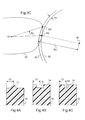
- control unit 251 acquires the three-dimensional geometry of a longitudinal profile 30 (see figure 3A ), illustrating the shape that should ideally present the contour of the ophthalmic lens 10 so that it can fit perfectly in the corresponding surrounding of the selected spectacle frame.
- This longitudinal profile 30 may for example be acquired in the form of a set of triplets, these triplets corresponding to the coordinates of a plurality of points characterizing the shape of this longitudinal profile 30.
- the longitudinal profile 30 will be acquired in a database register available to the optician.
- This database register regularly updated by the manufacturer of spectacle frames or by the ophthalmic lens manufacturer or even by the optician himself, comprises for this purpose a plurality of records each associated with a model of eyeglass frames. Each record then has an identifier of the model of the spectacle frame with which it is associated, and a set of 360 triplets characterizing the shape of the longitudinal profile of each surround of this spectacle frame model.
- the longitudinal profile 30 may be acquired using an imaging device having image capturing means and image processing means.
- the coordinates of the points characterizing the longitudinal profile 30 can be acquired by taking a picture of a presentation lens delivered with the spectacle frame, then by treating this photo so as to locate in this photo 360 points on its edge.
- the three-dimensional geometry of the longitudinal profile 30 can also be acquired otherwise, for example by probing with contact with the edge of the presentation lens.
- control unit 251 acquires the coordinates of two initial singular points P1, P2 of the longitudinal profile 30.
- the coordinates of these two initial singular points P1, P2 can to be acquired in different ways.
- each record of the aforementioned database register comprises two complementary triplets corresponding to the coordinates of the two initial singular points P1, P2 of the entourage of the model of the spectacle frame to which this recording is associated.
- the acquisition of the longitudinal profile 30 and the acquisition of its two initial singular points P1, P2 will be simultaneous and consist of a simple search, in the register, of a record corresponding to the selected spectacle frame.
- the acquisition of the positions of the two initial singular points P1, P2 along the longitudinal profile 30 is performed freehand by the optician.
- the control unit 251 can, for this purpose, after acquiring the three-dimensional geometry of the longitudinal profile 30, control the display of this longitudinal profile 30 on the display screen 253. In this way, the optician can then point , using the pointing device 255, the two initial singular points P1, P2 on the longitudinal profile 30.
- the longitudinal profile 30 will be displayed on the screen with a scale 1: 1, so that the optician can position the spectacle frame or the presentation lens in front of the display screen 253, facing the profile longitudinal 30 displayed, in order to locate with precision the positions of the two initial singular points P1, P2 along the longitudinal profile 30.
- the two initial singular points P1, P2 are angularly separated around the boxing center O1 of the longitudinal profile 30 of an initial angle THETA3 which is equal to the angle separating the two ends of the arcade 21A around the boxing center of the entourage 21.
- the boxing center is usually defined as being the center of the rectangle which is circumscribed in the longitudinal profile or the surrounding area, and whose two sides are parallel to the horizontal.
- control unit 10 divides the longitudinal profile 30 into two complementary initial arcs D1, D2 situated on either side of these two initial singular points P1, P2.
- a first initial arc D1 also called initial superior arc D1
- the second initial arc D2 also called second arc or lower arc D2
- the control unit 251 corrects the position of at least one of the two initial singular points P1, P2 to respectively obtain two final singular points P1 ', P2' situated in internal recess of the initial singular points P1, P2.
- These final singular points P1 ', P2' then delimit a first final arc D1 ', called in the final upper arc example D1', which constitutes a truncated correction of the initial upper arc D1: the length of this final upper arc D1 is reduced compared to that of the initial upper arc D1 of the longitudinal profile 30.
- the initial singular point P2 selected for correction is the point located on the side of the temporal portion of the longitudinal profile 30.
- the transition between the two finishes is indeed usually hidden by the nose pads of the eyeglass frame.
- control unit 251 corrects the positions of the two initial singular points P1, P2.
- the control unit 251 shifts these two points by a given distance. This difference can be expressed as a length in the curvilinear abscissa along the longitudinal profile. It can also express itself, as it appears on the figure 3A , in the form of an offset angle THETA1, THETA2 around the boxing center 01 of the longitudinal profile 30.
- this correction then consists in determining the points of the longitudinal profile 30, called final singular points P1 ', P2', which are respectively angularly separated from the two initial singular points P1, P2 of a first and a second offset angle THETA1 , THETA2.
- first and second offset angles THETA1, THETA2 are preferably greater than or equal to 5 degrees, so that the two final singular points P1 ', P2' are angularly separated around the boxing center 01 of a final angle THETA4 which is lower than initial angle THETA3 of at least 10 degrees.
- the offset angles THETA1, THETA2 can be predetermined and therefore invariable regardless of the shape of the selected spectacle frame 20.
- these offset angles THETA1, THETA2 are calculated based not only on the shape of the longitudinal profile 30, but also on the radius of the finishing tools 213, 214, 221 selected to machine the lens.
- the beveling wheel 213 has a large radius. Therefore, during the beveling operation, the angular portion of the beveling wheel that is engaged in the material of the lens is extended. Therefore, when the beveling grinding wheel mills the edge of the lens into a given cross-section of that lens, it also unintentionally mills part of the edge of the lens in front of that cross section and another part of the the edge of the lens behind this cross section. There is then a first interference between the beveling wheel and the bevel portion already made, and a second interference between the beveling wheel and the bevel portion that remains to be made. These interferences thus generate this phenomenon of thinning of the bevel.
- This figure shows the longitudinal profile 30, as well as the inner 32 and outer 33 profiles of the grinding wheel used to cut the ophthalmic lens (typically the bevel grinding wheel 213 or the grinding wheel 221).
- the outer profile 33 corresponds to the general profile of the grinding wheel
- the inner profile 32 corresponds to the profile of the bottom of the beveling groove of this grinding wheel.
- the creasing wheel 221 the outer profile 33 corresponds to the general profile of the creasing wheel
- the inner profile 32 corresponds to the profile of the nonactive part of this grinding wheel (that is, to say of the part which does not take part in the machining of the lens, considering the depth of depression of the grinding wheel in the edge of the lens).
- the radius of the outer profile 33 is noted R m while the gap between the inner 32 and outer 33 profiles is noted ⁇ P.
- this point of intersection corresponds to the final singular point P2 '.
- the control unit 10 defines a first final arc D1 ', referred to in the final upper arc example, corresponding to the part of the longitudinal profile 30 which is delimited between these two final singular points P1 ',', P2 '.
- This final upper arc D1 ' has a reduced length compared to that of the upper initial arc D1.
- the lower arc D2 remains defined as being that delimited between the two initial singular points P1, P2, so that the final lower arc D1 'and the upper arc D2 are no longer complementary.
- the control unit 251 controls the various degrees of freedom of the grinder 200 in a manner. to reduce coarsely the rays of the ophthalmic lens 10 previously locked between the clamping shafts 202, 203 of the grinder 200.
- the blank wheel 215 and the rocker 201 are driven relative to each other so as to reduce, for each angular position of the lens around the locking pin A7, the radius of the lens to a radius of length strictly greater than that of the corresponding radius of the longitudinal profile 30.
- control unit 251 controls the various degrees of freedom of the grinder 200 so as to bring back an upper portion E1 (see FIG. figure 9 ) of the contour of the lens to the shape of the first final arc D1 'of the longitudinal profile 30.
- control unit 251 controls the various degrees of freedom of the grinder 200 so as to bring a lower portion E2 of the contour of the lens to the shape of the second arc D2 longitudinal profile 30.
- first and second finishing steps are carried out so that the finishes (bevel 11, groove 12-13, flat finish 14) are different on the two parts E1, E2 of the contour of the ophthalmic lens 10
- the first finishing step is performed on the entire contour of the ophthalmic lens, while the second finishing step is performed on only a portion of the lens contour, that complementary to the upper portion E1.
- these finishes 11, 12, 13 are preferably made so that their mean lines extend at the same constant distance C1 from the front face of the ophthalmic lens 10.
- the wafer of the ophthalmic lens 10 is polished using the polishing wheels 211, 212 of the grinder 200.
- the first finishing step must then consist of a beveling operation of the upper portion E1 of the contour of the ophthalmic lens 10, while the second finishing step must consist of two grinding and creasing operations of the lower part E2 of the contour of the ophthalmic lens 10.
- the entire contour of the ophthalmic lens 10 is bevelled following a profile composed of the arches D1 '- D3 - D4 which is partly distinct from the longitudinal profile 30.
- the beveling grinding wheel 213 is more precisely controlled relative to the ophthalmic lens 10 so that the bottom of its bevelling groove 213A follows a profile which is merged with the final upper arc D1 of the longitudinal profile 30, but which is distinct from the lower arch D2.
- This arc D4 is distinguished here from the lower arc D2 in that it is spaced radially thereof from the boxing center O1 a constant F1 difference.
- This difference F1 is here chosen equal to the depth F2 of the beveling groove 213A of the beveling wheel ( figure 2 ).
- the ophthalmic lens 10 is bevelled following an arc of link D3 which extends from the final upper arc D1 'to the arc D4, thus deviating radially from the longitudinal profile 30.
- connection part E3 the contour of the ophthalmic lens 10 thus forms a rounded step which is progressive and continuous, the length of curvilinear abscissa is related to the value of the offset angle THETA1, THETA2 and whose height is equal to the depth F2 of the beveling groove 213A of the beveling wheel 213.
- the right grinding wheel 214 is driven relative to the ophthalmic lens 10 so that its working surface follows the longitudinal profile 30.
- the bevel 11 initially formed is entirely truncated and has a straight finish 14.
- the bevel 11 is partially truncated. Its vertex is thus progressively truncated from the final singular points P1 ', P2' where it is left intact, to the initial singular points P1, P2 where the bevel is entirely truncated.
- the height of the bevel 11 thus varies progressively on each of the connection portions E3 of the contour of the ophthalmic lens 10.
- the creasing wheel 221 is driven relative to the ophthalmic lens 10 so that, on the lower part E2 of the contour of the lens, its working surface follows an arc D6 which is radially spaced from the lower arc D2, the inner side of the longitudinal profile 30, a constant F3 gap.
- the creasing wheel 221 is thus controlled in the lower part E2 of the contour of the lens so that its working surface penetrates a desired depth F3 into the edge of the ophthalmic lens 10.
- the creasing wheel 221 is moreover controlled, on the connection portions E3 of the lens contour, in such a way that its working surface progressively deviates from the ophthalmic lens 10.
- each connecting portion E3 It is more precisely controlled, on each of these connecting portions E3, following an arc D5 which extends from the corresponding end of the arc D6 to the corresponding end of the final upper arc D1 '.
- the depth of the groove 13 obtained varies progressively along each connecting portion E3 of the lens contour, from a maximum depth F3 at the initial singular points P1, P2 to a zero depth at the final singular points P1 ', P2'.
- the non-truncated portion of the bevel 11 machined on the edge of the ophthalmic lens 10 extends over an angular sector of the contour of the ophthalmic lens which is smaller than the angular sector of the arcade of the eyeglass frame 20. In this way , the bevel 11 does not appear unsightly at the ends of the arcade of the spectacle frame 20.
- the groove 13 engages under the arcade of the eyeglass frame 20, so that the nylon thread 21A hooked close to this end of the arch may engage directly in the groove 13 without abutting against the edge of the ophthalmic lens 10, to the benefit of the aesthetics of the pair of spectacles thus obtained and the rigidity of the mounting of the ophthalmic lens 10 in its surroundings 21.
- the first finishing step must then consist of a bevelling operation of a first portion E1 of the contour of the ophthalmic lens 10, while the second finishing step must consist of a single operation of rectification of a second portion E2 of the contour of the ophthalmic lens 10.
- the first finishing step must then consist of a grinding operation ( figure 11A ) followed by a first creasing operation ( figure 11 B) a first portion E1 of the contour of the ophthalmic lens 10, to form a first groove 13 of given width and depth.
- the second finishing step must consist of a second creasing operation ( figure 11 C) a second portion E2 of the contour of the ophthalmic lens 10, to form a second groove 12 of width and / or depth different (s) from that (s) of the first groove 13.
- the entire contour of the ophthalmic lens 10 is ground according to the longitudinal profile 30.
- the right grinding wheel 214 is more precisely controlled relative to the ophthalmic lens 10 so that its working surface follows the entire longitudinal profile 30.
- the entire contour of the ophthalmic lens 10 is slotted so that the first groove 13 extends over the entire slice of the lens.
- the creasing wheel 221 is driven relative to the ophthalmic lens 10 so that its working surface follows a profile which is spaced radially from the longitudinal profile 30 by a constant value, chosen as a function of the desired depth. for the first groove 13.
- the creasing wheel 221 is then driven relative to the ophthalmic lens 10 so that its working surface returns to the portion of the first groove 13 which is located along the final upper arch D1 '.
- the creasing wheel 221 is more precisely controlled to crosswise transversely to widen the first groove 13 so as to form the second groove 12.
- the ophthalmic lens is slotted so that the junctions between its two grooves are abrupt and thus form two narrowing sections at the two final singular points P1 ', P2'.
- each groove 12, 13 to be adapted to the diameter of the nylon thread and the width of the rib provided along the inner face of the arcade of the spectacle frame.
Abstract
Description
La présente invention concerne de manière générale la préparation de lentilles ophtalmiques en vue de leur emboîtement dans des entourages de montures de lunettes.The present invention relates generally to the preparation of ophthalmic lenses for interlocking in eyeglass frames.
Elle concerne plus particulièrement un procédé de détourage d'une lentille ophtalmique en vue de son montage dans un entourage mixte d'une monture de lunettes.It relates more particularly to a method of trimming an ophthalmic lens for mounting in a mixed environment of a spectacle frame.
La partie technique du métier de l'opticien consiste à monter une paire de lentilles ophtalmiques correctrices sur une monture de lunettes sélectionnée par un porteur.The technical part of the optician's profession is to mount a pair of corrective ophthalmic lenses on a spectacle frame selected by a wearer.
Ce montage se décompose en trois opérations principales :
- l'acquisition de la géométrie d'un profil longitudinal représentatif de la forme du contour de l'un des entourages de la monture de lunettes sélectionnée,
- le centrage de la lentille ophtalmique considérée, qui consiste à positionner et à orienter convenablement ce profil longitudinal sur la lentille, de manière qu'une fois usinée suivant ce profil puis montée dans sa monture, la lentille soit correctement positionnée et orientée par rapport à l'oeil correspondant du porteur, exerçant ainsi au mieux la fonction optique pour laquelle elle a été conçue, puis
- le détourage de la lentille qui comporte une étape d'ébauche pour ramener son contour initialement circulaire à une forme proche de celle souhaitée, une étape de finition, et une étape de surfinition (polissage, chanfreinage, ...).
- the acquisition of the geometry of a longitudinal profile representative of the shape of the outline of one of the surroundings of the selected spectacle frame,
- the centering of the ophthalmic lens in question, which consists in correctly positioning and orienting this longitudinal profile on the lens, so that once machined according to this profile and then mounted in its frame, the lens is correctly positioned and oriented with respect to the lens. corresponding eye of the wearer, thus exerting at best the optical function for which it was designed, then
- the trimming of the lens which comprises a roughing step to return its initially circular contour to a shape close to that desired, a finishing step, and a finishing step (polishing, chamfering, ...).
Dans le cas des montures de lunettes semi-cerclées, l'entourage comporte une arcade qui épouse une partie supérieure du contour de la lentille et un fil nylon qui longe la partie inférieure du contour de la lentille afin de maintenir la lentille au contact de l'arcade. L'étape de finition consiste alors généralement en un rainage de la tranche de la lentille pour former une rainure d'emboîtement qui puisse accueillir non seulement le fil nylon, mais aussi une nervure prévue le long de la face interne de l'arcade.In the case of semi-rimmed eyeglass frames, the entourage has an arch that fits an upper portion of the lens contour and a nylon thread that runs along the lower portion of the lens contour to hold the lens in contact with the lens. 'arcade. The finishing step then generally consists of creasing the slice of the lens to form an interlocking groove that can accommodate not only the nylon yarn, but also a rib provided along the inner face of the yoke.
On constate parfois que l'assemblage de ces montures de lunettes semi-cerclées n'est pas parfaitement rigide, au risque que l'une ou l'autre des lentilles se déboîte de la monture de lunettes. Pour pallier ce manque de rigidité, on connaît du document
Actuellement, d'autres types de montures de lunettes à entourages apparaissent sur le marché.Currently, other types of eyeglass frame frames appear on the market.
On connaît par exemple des montures de lunettes dont chaque entourage présente une interruption. L'étape de finition de la lentille comporte alors une première opération de biseautage d'une majeure partie du contour de la lentille, et une seconde opération de rectification de la tranche de la lentille à l'aide d'une meule cylindrique de révolution, au niveau de l'interruption de l'entourage.For example, spectacle frames are known, each of which has an interruption. The finishing step of the lens then comprises a first beveling operation of a major part of the lens contour, and a second operation of grinding the edge of the lens with a cylindrical grinding wheel of revolution, at the level of the interruption of the entourage.
On connaît également des montures de lunettes semi-cerclées singulières, dans lesquelles la face intérieure de chaque arcade porte non pas une nervure mais une rainure d'emboîtement. L'étape de finition de la lentille, telle qu'elle est présentée dans le document
L'inconvénient majeur de ces procédés de détourage, dont les étapes de finition comportent deux opérations distinctes, est que les frontières entre les deux parties du contour de la lentille forment des discontinuités inesthétiques, puisqu'elles apparaissent aux extrémités de l'arcade (ou de l'entourage interrompu).The major disadvantage of these clipping methods, whose finishing steps comprise two distinct operations, is that the boundaries between the two parts of the lens contour form unsightly discontinuities, since they appear at the ends of the arcade (or interrupted entourage).
Dans le cas des montures de lunettes semi-cerclées singulières, ces discontinuités génèrent en outre des problèmes de maintien de la lentille dans son entourage.In the case of singular semi-rimless eyeglass frames, these discontinuities also generate problems of maintaining the lens in its surroundings.
Afin de remédier aux inconvénients précités, la présente invention propose un procédé de détourage d'une lentille ophtalmique tel que défini dans la revendication 1.In order to overcome the aforementioned drawbacks, the present invention provides a method of trimming an ophthalmic lens as defined in claim 1.
Ainsi, puisque la longueur du premier arc final est réduite, la frontière entre les deux finitions n'est plus positionnée au niveau de l'extrémité du premier tronçon de l'entourage (typiquement de l'arcade), mais en dessous de ce premier tronçon.Thus, since the length of the first final arc is reduced, the border between the two finishes is no longer positioned at the end of the first section of the entourage (typically the arcade), but below this first section.
Grâce à l'invention, les discontinuités situées à la frontière entre les deux parties du contour de la lentille se trouvent alors cachées sous le premier tronçon de l'entourage, au bénéfice de l'esthétisme de la paire de lunettes.Thanks to the invention, the discontinuities located at the border between the two parts of the outline of the lens are then hidden under the first section of the entourage, to the benefit of the aesthetics of the pair of glasses.
Par ailleurs, dans le cas des montures de lunettes semi-cerclées singulières, puisque la rainure débute alors sous les extrémités de l'arcade, le fil nylon peut s'engager directement dans la rainure, sans buter contre la nervure d'emboîtement, au profit de la rigidité de l'assemblage.Moreover, in the case of singular semi-rimless eyeglass frames, since the groove then begins under the ends of the arch, the nylon thread can engage directly in the groove, without abutting against the interlocking rib, at advantage of the rigidity of the assembly.
D'autres caractéristiques avantageuses et non limitatives du procédé de détourage conforme à l'invention sont définies dans les revendications 2 et suivantes.Other advantageous and non-limiting features of the trimming method according to the invention are defined in claims 2 and following.
La description qui va suivre, en regard des dessins annexés, donnée à titre d'exemple non limitatif, fera bien comprendre en quoi consiste l'invention et comment elle peut être réalisée.The description which follows, with reference to the accompanying drawings, given by way of non-limiting example, will make it clear what the invention consists of and how it can be achieved.
Sur les dessins annexés :
- la
figure 1 est une vue schématique en perspective d'un appareil de détourage adapté à mettre en oeuvre un procédé de détourage selon l'invention ; - la
figure 2 est une vue schématique en plan du train de meules de l'appareil de détourage de lafigure 1 ; - la
figure 3A est une vue schématique en plan d'un profil longitudinal d'un entourage d'une monture de lunettes ; - la
figure 3B est une vue schématique en perspective d'une paire de lunettes ; - la
figure 3C est une vue schématique en plan du profil longitudinal de lafigure 3A et du profil d'une meule de détourage ; - les
figures 4A à 4C sont des vues schématiques en coupe de sections transversales de trois lentilles ophtalmiques respectivement biseautée, rainée sur une largeur importante, et rainée sur une largeur réduite ; - les
figures 5 et 6 sont des vues schématiques en plan et en perspective d'une portion périphérique d'une lentille ophtalmique biseautée ; - les
figures 7 et 8 sont des vues schématiques en plan et en perspective de la lentille ophtalmique de lafigure 5 , dont une partie du contour a été rectifiée ; - les
figures 9 et 10 sont des vues schématiques en plan et en perspective de la lentille ophtalmique de lafigure 7 , dont une partie du contour a été rainée ; - les
figures 11A à 11C sont des vues schématiques en plan illustrant les opérations pour la finition d'une lentille ophtalmique rainée sur son contour avec deux rainures de largeurs différentes ; et - la
figure 12 est une vue schématique en perspective d'une portion périphérique de la lentille ophtalmique de lafigure 11C .
- the
figure 1 is a schematic perspective view of a trimming apparatus adapted to implement a trimming method according to the invention; - the
figure 2 is a schematic plan view of the wheel train of the trimming apparatus of thefigure 1 ; - the
figure 3A is a schematic plan view of a longitudinal profile of an entourage of a spectacle frame; - the
figure 3B is a schematic perspective view of a pair of glasses; - the
figure 3C is a schematic plan view of the longitudinal profile of thefigure 3A and the profile of a clipping wheel; - the
Figures 4A to 4C are schematic sectional views of cross-sections of three ophthalmic lenses respectively bevelled, grooved over a large width, and grooved over a reduced width; - the
Figures 5 and 6 are schematic views in plan and in perspective of a peripheral portion of a beveled ophthalmic lens; - the
Figures 7 and 8 are schematic plan and perspective views of the ophthalmic lens of thefigure 5 , part of which has been rectified; - the
Figures 9 and 10 are schematic plan and perspective views of the ophthalmic lens of thefigure 7 , part of whose contour has been slotted; - the
Figures 11A to 11C are schematic plan views illustrating the operations for finishing an ophthalmic lens grooved on its contour with two grooves of different widths; and - the
figure 12 is a schematic perspective view of a peripheral portion of the ophthalmic lens of thefigure 11C .
La présente invention concerne un procédé de détourage d'une lentille ophtalmique en vue de son montage dans un entourage d'une monture de lunettes à entourages mixtes.The present invention relates to a method of trimming an ophthalmic lens for mounting in an environment of a spectacle frame with mixed surrounds.
Par monture de lunettes à entourages mixtes, on entend toute monture dont chaque entourage comporte un tronçon interrompu ou deux tronçons distincts (c'est-à-dire deux tronçons équipés de moyens d'assujettissement de la lentille qui présentent des architectures différentes).Eyeglass frames with mixed surrounds means any frame each surround has an interrupted section or two distinct sections (that is to say two sections equipped with lens attachment means that have different architectures).
On s'intéressera dans le présent exposé à trois types particuliers de montures de lunettes à entourages mixtes.This presentation will focus on three particular types of spectacle frames with mixed surrounds.
Les deux premiers types de montures de lunettes sont des montures semi-cerclées.The first two types of spectacle frames are semi-rimmed frames.
Telle que représentée sur la
Le premier type de monture de lunettes, le plus classique, comporte, sur la face intérieure de chacune de ses arcades 21A, une nervure d'emboîtement agencée pour s'engager dans une rainure prévue sur la tranche de la lentille ophtalmique 10 correspondante.The first type of eyeglass frame, the most conventional, comprises, on the inner face of each of its
Le détourage de la lentille ophtalmique 10 comportera alors préférentiellement une étape de rainage au cours de laquelle deux rainures de largeurs différentes seront réalisées sur la tranche de la lentille, l'une adaptée aux dimensions de la nervure d'emboîtement et l'autre adaptée au diamètre du fil nylon.The trimming of the
Le second type de monture de lunettes, plus rare, comporte, sur la face intérieure de chacune de ses arcades 21A, une rainure d'emboîtement (ou « drageoir ») dans laquelle peut s'engager une nervure (ou « biseau ») prévue sur la tranche de la lentille ophtalmique 10 correspondante.The second type of eyeglass frame, more rare, comprises, on the inner face of each of its
Le détourage de la lentille ophtalmique 10 comportera alors une étape de biseautage d'une partie supérieure de son contour, suivie d'une étape de rainage d'une partie inférieure de son contour.The trimming of the
Le troisième type de monture de lunettes auquel on s'intéressera dans cet exposé comporte deux entourages présentant chacun une interruption, chaque entourage comportant alors uniquement une arcade (le premier tronçon).The third type of eyeglass frame to which we will focus in this presentation includes two circles each having an interruption, each entourage then comprising only an arcade (the first section).
Une lentille ophtalmique à monter sur une telle monture sera alors biseautée sur une majeure partie de son contour et rectifiée sur une partie restante de son contour (celle laissée visible par l'interruption) de manière à présenter une tranche « plane » sur cette partie de son contour.An ophthalmic lens to be mounted on such a mount will then be bevelled over a major part of its contour and rectified on a remaining part of its contour (that left visible by the interruption) so as to present a "flat" slice on this part of its outline.
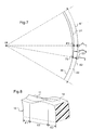
Pour la mise en oeuvre du procédé selon l'invention, on peut disposer d'un appareil de détourage réalisé sous la forme de toute machine de découpage ou d'enlèvement de matière apte à modifier le contour d'une lentille ophtalmique pour l'adapter à celui de l'entourage de la monture sélectionnée.For the implementation of the method according to the invention, it is possible to dispose of a trimming apparatus in the form of any cutting or removal machine capable of modifying the contour of an ophthalmic lens to adapt it. to that of the entourage of the selected mount.
Dans l'exemple schématisé sur la
une bascule 201 qui est montée librement pivotante autour d'un axe de référence A5, en pratique un axe horizontal, sur un châssis non représenté, et qui supporte la lentille ophtalmique 10 à usiner ;- un train de meules 210, qui est calé en rotation sur un axe de meule A6 parallèle à l'axe de référence A5, et qui est lui aussi dûment entraînée en rotation par un moteur non représenté ;
- un module de finition 220 qui est monté à rotation autour de l'axe de meule A6, et qui embarque une meule de rainage 221 de la lentille ophtalmique 10.
- a
latch 201 which is mounted freely pivotally about a reference axis A5, in practice a horizontal axis, on a frame not shown, and which supports theophthalmic lens 10 to be machined; - a
wheel set 210, which is set in rotation on a grinding wheel axis A6 parallel to the reference axis A5, and which is also properly rotated by a motor not shown; - a
finishing module 220 which is rotatably mounted around the wheel axis A6, and which embeds acreasing wheel 221 of theophthalmic lens 10.
La bascule 201 est équipée d'un support de lentille ici formé par deux arbres de serrage et d'entraînement en rotation 202, 203 de la lentille ophtalmique 10 à usiner.The
Ces deux arbres 202, 203 sont alignés l'un avec l'autre suivant un axe de blocage A7 parallèle à l'axe A5. Chacun des arbres 202, 203 possède une extrémité libre qui fait face à l'autre et qui est équipée d'un nez de blocage de la lentille ophtalmique 10.These two
Un premier des deux arbres 202 est fixe en translation suivant l'axe de blocage A7. Le second des deux arbres 203 est au contraire mobile en translation suivant l'axe de blocage A7 pour réaliser le serrage en compression axiale de la lentille ophtalmique 10 entre les deux nez de blocage.A first of the two
Tel que représenté schématiquement sur la
Ce train de meules 210 comporte en particulier :
- une meule d'ébauche 215 cylindrique de révolution autour de l'axe de meule A6, qui présente un diamètre de 155 millimètres et un grain important,
- une meule de rectification droite 214 cylindrique de révolution autour de l'axe de meule A6, qui présente un diamètre de 155 millimètres et un grain intermédiaire,
- une meule de biseautage 213 sensiblement identique à la meule de rectification droite 214, mais qui présente à mi-hauteur une gorge de biseautage 214A de section transversale triangulaire, et
- deux meules de polissage 211, 212 de géométries identiques aux meules de rectification droite 214 et de biseautage 213, mais qui présentent un grain réduit.
- a
roughing wheel 215 cylindrical in revolution around the grinding wheel axis A6, which has a diameter of 155 millimeters and a large grain, - a
straight grinding wheel 214 cylindrical in revolution about the grinding wheel axis A6, which has a diameter of 155 millimeters and an intermediate grain, - a
beveling wheel 213 substantially identical to theright grinding wheel 214, but having at mid-height a bevelling groove 214A of triangular cross-section, and - two polishing
wheels right grinding wheels 214 andbeveling 213, but which have a reduced grain.
La meule d'ébauche 215 est ainsi un outil d'ébauche permettant d'usiner grossièrement la lentille ophtalmique. Les meules de rectification droite 214 et de biseautage 213 sont des outils de finition permettant d'usiner la tranche de la lentille ophtalmique de manière à ce qu'elle présente un profil transversal particulier, adapté à la forme de l'entourage de la monture de lunettes sélectionnée. Les meules de polissage 211, 212 sont des outils de surfinition, agencés pour modifier l'état de surface de la tranche de la lentille ophtalmique.The
Le train de meules 210 est porté par un chariot, non représenté, monté mobile en translation suivant l'axe de meule A6. Le mouvement de translation du chariot porte-meules est appelé « transfert » TRA.The set of
On comprend qu'il s'agit ici de réaliser un mouvement relatif des meules par rapport à la lentille et que l'on pourra prévoir, en variante, une mobilité axiale de la lentille, les meules restant fixes.It is understood that it is a matter here of making a relative movement of the grinding wheels with respect to the lens and that it will be possible, in a variant, to provide an axial mobility of the lens, the grinding wheels remaining fixed.
La meuleuse 200 comporte, en outre, une biellette 230 dont une extrémité est articulée par rapport au châssis pour pivoter autour de l'axe de référence A5, et dont l'autre extrémité est articulée par rapport à une noix 231 pour pivoter autour d'un axe A8 parallèle à l'axe de référence A5.The
La noix 231 est elle-même montée mobile en translation suivant un axe de restitution A9 perpendiculaire à l'axe de référence A5. Telle que schématisée sur la
La biellette 230 comporte par ailleurs un capteur de contact 234, par exemple constitué par une cellule à effet Hall, qui interagit avec un élément correspondant de la bascule 201. On a noté B1 l'angle de pivotement de la biellette 230 autour de l'axe de référence A5 par rapport à l'horizontale. Cet angle B1 est linéairement associé à la translation verticale, notée RES (pour « restitution »), de la noix 231 suivant l'axe de restitution A9.The
Le module de finition 220 présente une mobilité de pivotement autour de l'axe de meule A6, appelée mobilité d'escamotage ESC. Concrètement, le module de finition 220 est pourvu d'une roue dentée (non représentée) qui engrène avec un pignon équipant l'arbre d'un moteur électrique solidaire du chariot porte-meules. Cette mobilité lui permet de se rapprocher ou de s'éloigner de la lentille ophtalmique 10.The
La meule de rainage 221 embarquée sur le module de finition 220 présente ici une forme de disque d'axe de révolution parallèle à l'axe de meule A6. Elle présente une épaisseur réduite, de l'ordre du millimètre, pour permettre de réaliser des rainures de largueurs réduites sur la tranche de la lentille ophtalmique 10. Cette meule de rainage 221 forme alors le troisième outil de finition de la meuleuse 200.The
Lorsque, dûment enserrée entre les deux arbres 202, 203, la lentille ophtalmique 10 à usiner est amenée au contact de l'une des meules du train de meules 210, elle est l'objet d'un enlèvement effectif de matière jusqu'à ce que la bascule 201 vienne buter contre la biellette 230 suivant un appui qui, se faisant au niveau du capteur de contact 234, est dûment détecté par celui-ci.When, duly sandwiched between the two
Pour l'usinage de la lentille ophtalmique 10 suivant un contour donné, il suffit, donc, d'une part, de déplacer en conséquence la noix 231 le long de l'axe de restitution A9, sous le contrôle du moteur 233, pour commander le mouvement de restitution RES et, d'autre part, de faire pivoter conjointement les arbres de support 202, 203 autour de l'axe de blocage A7. Le mouvement de restitution de la bascule 201 et le mouvement de rotation des arbres 202, 203 sont pilotés en coordination par une unité de pilotage 251, dûment programmée à cet effet, pour que tous les points du contour de la lentille ophtalmique 10 soient successivement ramenés au bon diamètre.For the machining of the
Cette unité de pilotage 251 est de type électronique et/ou informatique et permet en particulier de piloter :
- le moteur d'entraînement en translation du deuxième arbre 203 ;
- le moteur d'entraînement en rotation des deux arbres 202, 203 ;
- le moteur d'entraînement en translation du chariot porte-meules suivant la mobilité de transfert TRA ;
- le moteur 233 d'entraînement en translation de la noix 231 suivant la mobilité de restitution RES ;
- le moteur d'entraînement en rotation du module de finition 220 suivant la mobilité d'escamotage ESC ;
- le moteur d'entraînement en rotation de la meule de rainage 221.
- the drive motor in translation of the
second shaft 203; - the drive motor in rotation of the two
shafts - the drive motor in translation of the grinding carriage according to the transfer mobility TRA;
- the
motor 233 driving in translation of thenut 231 according to the restitution mobility RES; - the drive motor in rotation of the
finishing module 220 according to ESC retraction mobility; - the driving motor in rotation of the
creasing wheel 221.
La meuleuse 200 comporte enfin une interface Homme-Machine 252 qui comprend ici un écran d'affichage 253, un clavier 254 et un dispositif de pointage 255 (ici une souris) adaptés à communiquer avec l'unité de pilotage 251. Cette interface IHM 252 permet à l'utilisateur de saisir des valeurs numériques sur l'écran d'affichage 253 pour piloter en conséquence la meuleuse 200.The
Telle que représentée sur la
Le procédé de détourage de la lentille ophtalmique 10 en vue de son montage dans l'entourage de l'une des montures de lunettes précitées se décompose en plusieurs étapes successives.The method of trimming the
Au cours d'une première étape, l'unité de pilotage 251 acquiert la géométrie tridimensionnelle d'un profil longitudinal 30 (voir
Ce profil longitudinal 30 pourra par exemple être acquis sous la forme d'un ensemble de triplets, ces triplets correspondant aux coordonnées d'une pluralité de points caractérisant la forme de ce profil longitudinal 30.This
De manière préférentielle, le profil longitudinal 30 sera acquis dans un registre de base de données à la disposition de l'opticien. Ce registre de base de données, régulièrement mis à jour par le fabricant de montures de lunettes ou par le fabricant de lentilles ophtalmiques ou encore par l'opticien lui-même, comporte à cet effet une pluralité d'enregistrements chacun associé à un modèle de montures de lunettes. Chaque enregistrement comporte alors un identifiant du modèle de la monture de lunettes auquel il est associé, et un ensemble de 360 triplets caractérisants la forme du profil longitudinal de chaque entourage de ce modèle de monture de lunettes.Preferably, the
En variante, le profil longitudinal 30 pourra être acquis à l'aide d'un dispositif d'imagerie comportant des moyens de capture d'images et des moyens de traitement d'images. Grâce à ce dispositif d'imagerie, les coordonnées des points caractérisant le profil longitudinal 30 pourront être acquises en prenant une photo d'une lentille de présentation livrée avec la monture de lunettes, puis en traitant cette photo de manière à repérer sur cette photo 360 points situés sur sa tranche.Alternatively, the
La géométrie tridimensionnelle du profil longitudinal 30 pourra également être acquise autrement, par exemple par palpage avec contact de la tranche de la lentille de présentation.The three-dimensional geometry of the
Au cours d'une seconde étape, l'unité de pilotage 251 acquiert les coordonnées de deux points singuliers initiaux P1, P2 du profil longitudinal 30.During a second step, the
Ces deux points singuliers initiaux P1, P2 correspondent aux points qui, une fois la paire de lunettes assemblée, seront situés au niveau des extrémités de l'arcade (si la monture est semi cerclée) ou des extrémités de l'interruption de l'entourage (si la monture est du troisième type).These two initial singular points P1, P2 correspond to the points which, once the pair of glasses assembled, will be located at the ends of the arch (if the frame is semi-circled) or the ends of the interruption of the entourage (if the mount is of the third type).
Les coordonnées de ces deux points singuliers initiaux P1, P2 peuvent être acquises de différentes manières.The coordinates of these two initial singular points P1, P2 can to be acquired in different ways.
De manière préférentielle, on pourra les acquérir en prévoyant que chaque enregistrement du registre de base de données précité comporte deux triplets complémentaires correspondant aux coordonnées des deux points singuliers initiaux P1, P2 de l'entourage du modèle de la monture de lunettes auquel cet enregistrement est associé. Ainsi, l'acquisition du profil longitudinal 30 et l'acquisition de ses deux points singuliers initiaux P1, P2 seront simultanées et consisteront en une simple recherche, dans le registre, d'un enregistrement correspondant à la monture de lunettes sélectionnée.Preferably, they can be acquired by providing that each record of the aforementioned database register comprises two complementary triplets corresponding to the coordinates of the two initial singular points P1, P2 of the entourage of the model of the spectacle frame to which this recording is associated. Thus, the acquisition of the
En variante, on pourra prévoir que l'acquisition des positions des deux points singuliers initiaux P1, P2 le long du profil longitudinal 30 soit réalisée à main levée par l'opticien.Alternatively, it can be provided that the acquisition of the positions of the two initial singular points P1, P2 along the
L'unité de pilotage 251 pourra à cet effet, après avoir acquis la géométrie tridimensionnelle du profil longitudinal 30, commander l'affichage de ce profil longitudinal 30 sur l'écran d'affichage 253. De cette manière, l'opticien pourra ensuite pointer, à l'aide du dispositif de pointage 255, les deux points singuliers initiaux P1, P2 sur le profil longitudinal 30.The
Avantageusement alors, le profil longitudinal 30 sera affiché à l'écran avec une échelle 1 :1, de manière que l'opticien puisse positionner la monture de lunettes ou la lentille de présentation devant l'écran d'affichage 253, en regard du profil longitudinal 30 affiché, afin de repérer avec précision les positions des deux points singuliers initiaux P1, P2 le long du profil longitudinal 30.Advantageously then, the
Par conséquent, les deux points singuliers initiaux P1, P2 sont séparés angulairement autour du centre boxing O1 du profil longitudinal 30 d'un angle initial THETA3 qui est égal à l'angle séparant les deux extrémités de l'arcade 21A autour du centre boxing de l'entourage 21.Consequently, the two initial singular points P1, P2 are angularly separated around the boxing center O1 of the
On rappelle à cet effet que le centre boxing est, de manière usuelle, défini comme étant le centre du rectangle qui est circonscrit au profil longitudinal ou à l'entourage, et dont deux des côtés sont parallèles à l'horizontal.To this end, it is recalled that the boxing center is usually defined as being the center of the rectangle which is circumscribed in the longitudinal profile or the surrounding area, and whose two sides are parallel to the horizontal.
Comme le montre la
Un premier arc initial D1, appelé aussi arc supérieur initial D1, correspond à la partie du profil longitudinal 30 qui sera située à hauteur de l'arcade 21A, tandis que le second arc initial D2, appelé aussi second arc ou arc inférieur D2, correspond à la partie du profil longitudinal 30 qui sera située à hauteur du fil nylon 21 B.A first initial arc D1, also called initial superior arc D1, corresponds to the portion of the
Au cours d'une troisième étape, comme le montre la
Grâce à cette réduction de longueur, la frontière entre les deux finitions à réaliser sur la tranche de la lentille (biseau, finition droite ou rainure) est ramenée sous l'arcade 21A, de manière que cette transition ne soit pas visible.With this reduction in length, the border between the two finishes to be made on the edge of the lens (bevel, straight finish or groove) is brought under the arch 21A, so that this transition is not visible.
Dans le cas où seule la position de l'un des deux points singuliers initiaux P1, P2 est corrigée, alors le point singulier initial P2 sélectionné pour être corrigé est le point situé du côté de la partie temporale du profil longitudinal 30. Du côté nasal, la transition entre les deux finitions est en effet généralement cachée par les plaquettes nasales de la monture de lunettes.In the case where only the position of one of the two initial singular points P1, P2 is corrected, then the initial singular point P2 selected for correction is the point located on the side of the temporal portion of the
Toutefois, ici, l'unité de pilotage 251 corrige les positions des deux points singuliers initiaux P1, P2.However, here, the
Pour corriger les positions des deux points singuliers initiaux P1, P2 et obtenir ainsi les points singuliers finaux P1', P2', l'unité de pilotage 251 procède à un décalage de ces deux points d'un écart donné. Cet écart peut s'exprimer sous la forme d'une longueur en abscisse curviligne le long du profil longitudinal. Il peut également s'exprimer, comme cela apparaît sur la
Tel que représenté sur la
Ces premier et second angles de décalage THETA1, THETA2 sont préférentiellement supérieurs ou égaux à 5 degrés, de sorte que les deux points singuliers finaux P1', P2' sont séparés angulairement autour du centre boxing 01 d'un angle final THETA4 qui est inférieur audit angle initial THETA3 d'au moins 10 degrés.These first and second offset angles THETA1, THETA2 are preferably greater than or equal to 5 degrees, so that the two final singular points P1 ', P2' are angularly separated around the boxing center 01 of a final angle THETA4 which is lower than initial angle THETA3 of at least 10 degrees.
Les angles de décalage THETA1, THETA2 peuvent être prédéterminés et donc invariables quelle que soit la forme de la monture de lunettes 20 sélectionnée.The offset angles THETA1, THETA2 can be predetermined and therefore invariable regardless of the shape of the selected
Toutefois, ici, ces angles de décalage THETA1, THETA2 sont calculés en fonction non seulement de la forme du profil longitudinal 30, mais aussi en fonction du rayon des outils de finition 213, 214, 221 sélectionnés pour usiner la lentille.However, here, these offset angles THETA1, THETA2 are calculated based not only on the shape of the
Ces angles de décalage THETA1, THETA2 sont en effet calculés en tenant compte des phénomènes de rognage du biseau 11 de la lentille ophtalmique 10.These offset angles THETA1, THETA2 are indeed calculated taking into account the trimming phenomena of the
Ce phénomène, communément appelé « rognage du biseau », s'explique ainsi. La meule de biseautage 213 présente un rayon important. De ce fait, lors de l'opération de biseautage, la portion angulaire de la meule de biseautage qui est engagée dans la matière de la lentille est étendue. Par conséquent, lorsque la meule de biseautage usine le chant de la lentille en une section transversale donnée de cette lentille, elle usine également, de manière involontaire, une partie du chant de la lentille située en avant de cette section transversale et une autre partie du chant de la lentille située en arrière de cette section transversale. On observe alors une première interférence entre la meule de biseautage et la portion de biseau déjà réalisée, et une seconde interférence entre la meule de biseautage et la portion de biseau qui reste à réaliser. Ces interférences génèrent ainsi ce phénomène d'amincissement du biseau.This phenomenon, commonly called "trimming bevel", is explained as well. The
Le calcul des angles de décalage THETA1, THETA2 permet alors de tenir compte de ces interférences, de manière à positionner au mieux les points singuliers corrigés P1', P2' sur le profil longitudinal 30.Calculation of the offset angles THETA1, THETA2 then makes it possible to take these interferences into account, so as to better position the corrected singular points P1 ', P2' on the
Un exemple de méthode de détermination de ces angles de décalage THETA1, THETA2 est illustrée sur la
Sur cette figure, on a représenté le profil longitudinal 30, ainsi que les profils intérieur 32 et extérieur 33 de la meule utilisée pour détourer la lentille ophtalmique (typiquement la meule de biseautage 213 ou la meule de rainage 221). S'il s'agit de la meule de biseautage 213, le profil extérieur 33 correspond au profil général de la meule, tandis que le profil intérieur 32 correspond au profil du fond de la gorge de biseautage de cette meule. S'il s'agit de la meule de rainage 221, le profil extérieur 33 correspond au profil général de la meule de rainage, tandis que le profil intérieur 32 correspond au profil de la partie non active de cette meule (c'est-à-dire de la partie qui ne participe pas à l'usinage de la lentille, eu égard à la profondeur d'enfoncement de la meule dans le chant de la lentille).This figure shows the
Sur la
La méthode de détermination de l'angle de décalage THETA2 consiste alors à :
- déterminer la position relative des profils 32, 33 de la meule par rapport au profil longitudinal 30 lorsque la meule est correctement positionnée pour usiner la lentille ophtalmique au point singulier initial P2 (c'est-à-dire lorsque la meule est tangente au profil longitudinal 30 au niveau du point singulier initial P2), puis à
- déterminer l'angle (autour du centre boxing O1) entre le point singulier initial P2 et le point d'intersection entre le profil extérieur 33 et le profil longitudinal 30.
- determining the relative position of the
grinding wheel profiles longitudinal profile 30 when the grinding wheel is correctly positioned to machine the ophthalmic lens at the initial singular point P2 (ie when the grinding wheel is tangent to thelongitudinal profile 30 at the initial singular point P2), then at - determine the angle (around the boxing center O1) between the initial singular point P2 and the point of intersection between the
outer profile 33 and thelongitudinal profile 30.
Dans cette méthode, ce point d'intersection correspond du reste au point singulier final P2'.In this method, this point of intersection corresponds to the final singular point P2 '.
Comme le montre la
L'arc inférieur D2 reste quant à lui défini comme étant celui délimité entre les deux points singuliers initiaux P1, P2, si bien que l'arc inférieur final D1' et l'arc supérieur D2 ne sont plus complémentaires.The lower arc D2 remains defined as being that delimited between the two initial singular points P1, P2, so that the final lower arc D1 'and the upper arc D2 are no longer complementary.
Au cours d'une quatrième étape, appelée étape d'ébauche, l'unité de pilotage 251 pilote les différents degrés de liberté de la meuleuse 200 de manière à réduire grossièrement les rayons de la lentille ophtalmique 10 préalablement bloquée entre les arbres de serrage 202, 203 de la meuleuse 200.During a fourth step, called the roughing step, the
La meule d'ébauche 215 et la bascule 201 sont à cet effet pilotées l'une relativement à l'autre de manière à réduire, pour chaque position angulaire de la lentille autour de l'axe de blocage A7, le rayon de la lentille à un rayon de longueur strictement supérieure à celle du rayon correspondant du profil longitudinal 30.For this purpose, the
Au cours d'une cinquième étape, appelée première étape de finition, l'unité de pilotage 251 pilote les différents degrés de liberté de la meuleuse 200 de manière à ramener une partie supérieure E1 (voir
Au cours d'une sixième étape, appelée seconde étape de finition, l'unité de pilotage 251 pilote les différents degrés de liberté de la meuleuse 200 de manière à ramener une partie inférieure E2 du contour de la lentille à la forme du second arc D2 du profil longitudinal 30.During a sixth step, called the second finishing step, the
Ces première et seconde étapes de finition sont réalisées de manière à ce que les finitions (biseau 11, rainure 12 - 13, finition plate 14) soient différentes sur les deux parties E1, E2 du contour de la lentille ophtalmique 10These first and second finishing steps are carried out so that the finishes (
Avantageusement, la première étape de finition est réalisée sur l'ensemble du contour de la lentille ophtalmique, tandis que la seconde étape de finition n'est réalisée que sur une partie seulement du contour de la lentille, celle complémentaire de la partie supérieure E1.Advantageously, the first finishing step is performed on the entire contour of the ophthalmic lens, while the second finishing step is performed on only a portion of the lens contour, that complementary to the upper portion E1.
Comme le montre les
Au cours d'une septième et dernière étape, la tranche de la lentille ophtalmique 10 est polie à l'aide des meules de polissage 211, 212 de la meuleuse 200.During a seventh and last step, the wafer of the
Dans la suite de cet exposé, on décrira en détail trois exemples de mise en oeuvre des deux étapes de finition, prévus pour respectivement détourer trois lentilles ophtalmiques à monter sur des montures de lunettes du premier type, du second type et du troisième type.In the remainder of this description, three examples of implementation of the two finishing steps, provided respectively for respectively cutting three ophthalmic lenses to be mounted on spectacle frames of the first type, the second type and the third type, will be described in detail.
Considérons tout d'abord le cas où la monture de lunettes sélectionnée est du second type.Consider first the case where the selected eyeglass frame is of the second type.
Comme le montre la
En référence à la
Toutefois, ici, comme le montrent plus précisément les
Au cours de cette opération de biseautage, la meule de biseautage 213 est plus précisément pilotée par rapport à la lentille ophtalmique 10 de manière à ce que le fond de sa gorge de biseautage 213A suive un profil qui est confondu avec l'arc supérieur final D1' du profil longitudinal 30, mais qui est distinct de l'arc inférieur D2.During this beveling operation, the
La partie inférieure E2 du contour de la lentille ophtalmique 10, située entre les deux points singuliers initiaux P1, P2, est alors biseautée en suivant un arc noté D4, qui est distinct de l'arc inférieur D2 du profil longitudinal 30 mais qui s'étend sur un même secteur angulaire que celui-ci.The lower part E2 of the contour of the
Cet arc D4 se distingue ici de l'arc inférieur D2 en ce qu'il est écarté radialement de celui-ci autour du centre boxing O1 d'un écart F1 constant. Cet écart F1 est ici choisi égal à la profondeur F2 de la gorge de biseautage 213A de la meule de biseautage (
Comme le montre la
Comme le montre la
Au cours de la seconde étape de finition, seule une portion du contour de la lentille ophtalmique 10 est rectifiée puis rainée. Cette portion du contour de la lentille est formée de la partie inférieure E2 et des deux parties de liaison E3 qui s'étendent de part et d'autre de la partie inférieure E2.During the second finishing step, only a portion of the contour of the
Comme le montre les
De cette manière, sur la partie inférieure E2 du contour de la lentille ophtalmique 10, le biseau 11 initialement formé est entièrement tronqué et présente une finition droite 14.In this way, on the lower part E2 of the contour of the
Sur les parties de liaison E3 du contour de la lentille ophtalmique 10, le biseau 11 est en revanche partiellement tronqué. Son sommet est ainsi progressivement tronqué depuis les points singuliers finaux P1', P2' où il est laissé intact, jusqu'aux points singuliers initiaux P1, P2 où le biseau est entièrement tronqué.On the connection portions E3 of the contour of the
A l'issue de cette opération de rectification, la hauteur du biseau 11 varie donc progressivement sur chacune des parties de liaison E3 du contour de la lentille ophtalmique 10.At the end of this grinding operation, the height of the
Comme le montre les
La meule de rainage 221 est ainsi pilotée dans la partie inférieure E2 du contour de la lentille de telle sorte que sa surface de travail s'enfonce d'une profondeur F3 souhaitée dans la tranche de la lentille ophtalmique 10.The
La meule de rainage 221 est par ailleurs pilotée, sur les parties de liaison E3 du contour de la lentille, de telle manière que sa surface de travail s'écarte progressivement de la lentille ophtalmique 10.The
Elle est plus précisément pilotée, sur chacune de ces parties de liaison E3, suivant un arc D5 qui s'étend depuis l'extrémité correspondante de l'arc D6 jusqu'à l'extrémité correspondante de l'arc supérieur final D1'. De cette manière, la profondeur de la rainure 13 obtenue varie progressivement tout le long de chaque partie de liaison E3 du contour de la lentille, depuis une profondeur maximale F3 au niveau des points singuliers initiaux P1, P2 jusqu'à une profondeur nulle au niveau des points singuliers finaux P1', P2'.It is more precisely controlled, on each of these connecting portions E3, following an arc D5 which extends from the corresponding end of the arc D6 to the corresponding end of the final upper arc D1 '. In this way, the depth of the
En définitive, comme le montre la
La rainure 13 prend quant à elle naissance sous l'arcade de la monture de lunettes 20, de telle sorte que le fil nylon 21A accroché à proximité de cette extrémité de l'arcade peut s'engager directement dans la rainure 13, sans buter contre la tranche de la lentille ophtalmique 10, au bénéfice de l'esthétisme de la paire de lunettes ainsi obtenue et de la rigidité du montage de la lentille ophtalmique 10 dans son entourage 21.The
Considérons maintenant le cas où la monture de lunettes sélectionnée est du troisième type.Consider now the case where the selected spectacle frame is of the third type.
Comme le montre la
Ces opérations de biseautage et de rectification pourront alors être réalisées de la même manière que précédemment.These beveling and grinding operations can then be performed in the same manner as before.
En variante, on pourra simplement prévoir de biseauter la première partie E1 du contour de la lentille ophtalmique 10, entre les deux points singuliers finaux P1', P2', puis de rectifier la partie restante du contour de la lentille ophtalmique 10, en suivant le profil longitudinal 30.Alternatively, it will be possible simply to bevel the first portion E1 of the contour of the
Considérons enfin le cas où la monture de lunettes sélectionnée est du premier type.Consider finally the case where the selected spectacle frame is of the first type.
Comme le montre la
La seconde étape de finition doit quant à elle consister en une opération de second rainage (
Ici, au cours de l'opération de rectification, l'ensemble du contour de la lentille ophtalmique 10 est rectifié en suivant le profil longitudinal 30.Here, during the grinding operation, the entire contour of the
Au cours de cette opération de rectification, la meule de rectification droite 214 est plus précisément pilotée par rapport à la lentille ophtalmique 10 de manière à ce que sa surface de travail suive l'ensemble du profil longitudinal 30.During this grinding operation, the
Au cours de l'opération de premier rainage, l'ensemble du contour de la lentille ophtalmique 10 est rainé de telle sorte que la première rainure 13 s'étende sur l'ensemble de la tranche de la lentille.During the first creasing operation, the entire contour of the
La meule de rainage 221 est à cet effet pilotée par rapport à la lentille ophtalmique 10 de manière à ce que sa surface de travail suive un profil qui est écarté radialement du profil longitudinal 30 d'une valeur constante, choisie en fonction de la profondeur souhaitée pour la première rainure 13.For this purpose, the
Au cours de l'opération de second rainage, la meule de rainage 221 est ensuite pilotée par rapport à la lentille ophtalmique 10 de manière à ce que sa surface de travail repasse dans la partie de la première rainure 13 qui est située le long de l'arc supérieur final D1'. Dans cette partie, la meule de rainage 221 est plus précisément pilotée pour louvoyer transversalement afin d'élargir la première rainure 13 de manière à former la seconde rainure 12.During the second creasing operation, the
Elle est par ailleurs pilotée pour louvoyer avec une amplitude constante le long de l'arc supérieur final D1', de manière que la seconde rainure 12 présente une largeur constante, et pour louvoyer avec une amplitude qui se réduit jusqu'à une valeur nulle le long des arcs de jonction D3, de manière à ce que les jonctions des deux rainures 12, 13 soient progressives.It is furthermore controlled to tack with a constant amplitude along the final upper arc D1 ', so that the
En variante, on pourrait bien sur prévoir que la lentille ophtalmique soit rainée de manière que les jonctions entre ses deux rainures soient brutales et qu'elles forment ainsi deux rétrécissements de sections au niveau des deux points singuliers finaux P1', P2'.Alternatively, it could of course be provided that the ophthalmic lens is slotted so that the junctions between its two grooves are abrupt and thus form two narrowing sections at the two final singular points P1 ', P2'.
Quoi qu'il en soit, cette différence de largeurs entre les deux rainures permet ici à chaque rainure 12, 13 d'être adaptée au diamètre du fil nylon et à la largeur de la nervure prévue le long de la face intérieure de l'arcade de la monture de lunettes.Anyway, this difference in widths between the two grooves here allows each
Claims (15)
caractérisé en ce que, à l'étape b), on corrige la position d'au moins l'un des deux points singuliers initiaux (P1, P2) de manière à obtenir deux points singuliers finaux (P1', P2') délimitant ledit premier arc final (D1'), ce dernier étant tronqué de telle sorte que sa longueur soit réduite par rapport à celle d'un premier arc initial (D1) du profil longitudinal (30) s'étendant entre les deux points singuliers initiaux (P1, P2) du profil longitudinal (30).A method of trimming an ophthalmic lens (10) for mounting in a mixed surround (21) of an eyeglass frame (20), comprising:
characterized in that , in step b), the position of at least one of the two initial singular points (P1, P2) is corrected so as to obtain two final singular points (P1 ', P2') delimiting said first final arc (D1 '), the latter being truncated so that its length is reduced relative to that of a first initial arc (D1) of the longitudinal profile (30) extending between the two initial singular points (P1 , P2) of the longitudinal profile (30).
Applications Claiming Priority (1)
| Application Number | Priority Date | Filing Date | Title |
|---|---|---|---|
| FR1003565A FR2964336B1 (en) | 2010-09-07 | 2010-09-07 | METHOD FOR DISTRESSING AN OPHTHALMIC LENS |
Publications (2)
| Publication Number | Publication Date |
|---|---|
| EP2425926A1 true EP2425926A1 (en) | 2012-03-07 |
| EP2425926B1 EP2425926B1 (en) | 2013-01-09 |
Family
ID=44124891
Family Applications (1)
| Application Number | Title | Priority Date | Filing Date |
|---|---|---|---|
| EP20110290347 Active EP2425926B1 (en) | 2010-09-07 | 2011-07-28 | Method for trimming an ophthalmic lens |
Country Status (3)
| Country | Link |
|---|---|
| US (1) | US8926401B2 (en) |
| EP (1) | EP2425926B1 (en) |
| FR (1) | FR2964336B1 (en) |
Cited By (1)
| Publication number | Priority date | Publication date | Assignee | Title |
|---|---|---|---|---|
| US20210308971A1 (en) * | 2018-05-09 | 2021-10-07 | Essilor International | Method for manufacturing an ophthalmic lens to be mounted in a frame, ophthalmic lens, frame and eyeglasses equipment |
Families Citing this family (4)
| Publication number | Priority date | Publication date | Assignee | Title |
|---|---|---|---|---|
| JP6034582B2 (en) * | 2012-03-29 | 2016-11-30 | Hoya株式会社 | Eyeglass lens manufacturing method, circumference calculation device, and circumference calculation program |
| FR2990369B1 (en) * | 2012-05-09 | 2014-08-29 | Essilor Int | METHOD FOR DISTRESSING A MULTILAYER OPHTHALMIC LENS |
| US10748091B1 (en) | 2020-01-16 | 2020-08-18 | Applied Underwriters, Inc. | Forecasting digital reservoir controller |
| EP4001998A1 (en) | 2020-11-20 | 2022-05-25 | Essilor International | System and process for edging ophthalmic lenses |
Citations (3)
| Publication number | Priority date | Publication date | Assignee | Title |
|---|---|---|---|---|
| US5347762A (en) * | 1992-02-04 | 1994-09-20 | Nidek Co., Ltd. | Lens periphery processing apparatus, method for obtaining processing data, and lens periphery processing method |
| EP1266722A1 (en) | 2000-06-15 | 2002-12-18 | Nidek Co., Ltd. | Eyeglass lens processing apparatus |
| EP1815941A1 (en) * | 2006-02-03 | 2007-08-08 | Nidek Co., Ltd | Eyeglass lens processing apparatus |
Family Cites Families (6)
| Publication number | Priority date | Publication date | Assignee | Title |
|---|---|---|---|---|
| EP1188516A4 (en) * | 2000-02-23 | 2004-12-08 | Shinetsu Handotai Kk | Method and apparatus for polishing outer peripheral chamfered part of wafer |
| US6758733B2 (en) * | 2002-03-13 | 2004-07-06 | Ronald C. Wiand | Two-part beveling wheel for improved positioning of bevel contours on ophthalmic lenses |
| FR2907041B1 (en) * | 2006-10-13 | 2008-12-26 | Essilor Int | METHOD FOR DISTRESSING AN OPHTHALMIC LENS |
| FR2912335B1 (en) * | 2007-02-13 | 2009-04-17 | Essilor Int | MACHINE FOR DETOURING A LENS OF GLASSES, PROVIDED WITH A ROTATING TOOL HOLDER ON WHICH ARE MADE SEVERAL WORKING TOOLS |
| FR2926896B1 (en) * | 2008-01-28 | 2010-03-19 | Essilor Int | PROCESS FOR PREPARING AN OPHTLUM LENS WITH SPECIFIC MACHINING OF ITS RIB |
| FR2962676B1 (en) * | 2010-07-13 | 2012-08-03 | Essilor Int | METHOD FOR DETOURING AN OPHTHALMIC LENS OF LENSES COMPRISING A COATING FILM |
-
2010
- 2010-09-07 FR FR1003565A patent/FR2964336B1/en not_active Expired - Fee Related
-
2011
- 2011-07-28 EP EP20110290347 patent/EP2425926B1/en active Active
- 2011-09-01 US US13/223,401 patent/US8926401B2/en active Active
Patent Citations (3)
| Publication number | Priority date | Publication date | Assignee | Title |
|---|---|---|---|---|
| US5347762A (en) * | 1992-02-04 | 1994-09-20 | Nidek Co., Ltd. | Lens periphery processing apparatus, method for obtaining processing data, and lens periphery processing method |
| EP1266722A1 (en) | 2000-06-15 | 2002-12-18 | Nidek Co., Ltd. | Eyeglass lens processing apparatus |
| EP1815941A1 (en) * | 2006-02-03 | 2007-08-08 | Nidek Co., Ltd | Eyeglass lens processing apparatus |
Cited By (2)
| Publication number | Priority date | Publication date | Assignee | Title |
|---|---|---|---|---|
| US20210308971A1 (en) * | 2018-05-09 | 2021-10-07 | Essilor International | Method for manufacturing an ophthalmic lens to be mounted in a frame, ophthalmic lens, frame and eyeglasses equipment |
| US11787136B2 (en) * | 2018-05-09 | 2023-10-17 | Essilor International | Method for manufacturing an ophthalmic lens to be mounted in a frame, ophthalmic lens, frame and eyeglasses equipment |
Also Published As
| Publication number | Publication date |
|---|---|
| US8926401B2 (en) | 2015-01-06 |
| US20120058714A1 (en) | 2012-03-08 |
| EP2425926B1 (en) | 2013-01-09 |
| FR2964336A1 (en) | 2012-03-09 |
| FR2964336B1 (en) | 2012-09-14 |
Similar Documents
| Publication | Publication Date | Title |
|---|---|---|
| EP2046529B1 (en) | Pair of ophthalmic glasses and method for forming a peripheral mounting rib on the edge of a lens | |
| EP2076358B1 (en) | Device for machining ophthalmic lenses comprising a plurality of machine tools positioned on an orientable module | |
| EP1807244B1 (en) | Device and method for adjusting the drilling direction of a drilling tool for an ophthalmic lens | |
| EP2410372B1 (en) | Method for calculating a setting for bevelling or scoring an ophthalmic lens | |
| EP2425926B1 (en) | Method for trimming an ophthalmic lens | |
| EP2247407B1 (en) | Method for preparing an ophthalmic lens with specific machining of the fitting rib thereof | |
| EP2210703B1 (en) | Eyeglass lens processing apparatus | |
| EP2760631B1 (en) | Method for trimming an opthalmic lens | |
| EP2268997B1 (en) | Apparatus and method for acquiring the shape of a spectacle frame circle or arcade | |
| FR2893524A1 (en) | Ophthalmic lens trimming method for spectacle frame, involves dynamically moving two axes of rotation relative to each other so that tangent to curve of machining portion of grinding wheel edge is parallel to tangent to curve of lens bevel | |
| EP2234758B1 (en) | Method for preparing an ophthalmic lens with specific machining of the fitting rib thereof | |
| FR3008914A1 (en) | METHOD AND MACHINE FOR ETCHING OPTICAL LENSES | |
| CA2904024C (en) | Device for cutting an ophthalmic lens | |
| FR2887168A1 (en) | Ophthalmic lens trimming method for spectacles, involves completing edging of lens` edge by using edge finishing grinding wheel with beveling gorge and by finishing machining of bevel, and edging edge by rough grinding machining of bevel | |
| EP2846969B1 (en) | Method for cutting-out a multi-layer ophthalmic lens | |
| EP2247408B1 (en) | Visual device including an ophthalmic lens having a partially cropped insertion rib, and method for preparing such lens | |
| EP2253427B1 (en) | Apparatus and method for preparing assembly of an ophthalmic eyeglass lens | |
| EP2399709B1 (en) | Process for the calculation and simulation of a peripheral mounting rib on the edge of a spectacle lens and bevelling process | |
| WO2006045965A1 (en) | Method for finishing or correction of the profile of the periphery of an ophthalmic lens following an edge profile |
Legal Events
| Date | Code | Title | Description |
|---|---|---|---|
| AK | Designated contracting states |
Kind code of ref document: A1 Designated state(s): AL AT BE BG CH CY CZ DE DK EE ES FI FR GB GR HR HU IE IS IT LI LT LU LV MC MK MT NL NO PL PT RO RS SE SI SK SM TR |
|
| AX | Request for extension of the european patent |
Extension state: BA ME |
|
| PUAI | Public reference made under article 153(3) epc to a published international application that has entered the european phase |
Free format text: ORIGINAL CODE: 0009012 |
|
| 17P | Request for examination filed |
Effective date: 20120712 |
|
| GRAP | Despatch of communication of intention to grant a patent |
Free format text: ORIGINAL CODE: EPIDOSNIGR1 |
|
| RIC1 | Information provided on ipc code assigned before grant |
Ipc: B24B 9/14 20060101AFI20120731BHEP Ipc: G02C 13/00 20060101ALI20120731BHEP Ipc: B24B 51/00 20060101ALI20120731BHEP |
|
| RIN1 | Information on inventor provided before grant (corrected) |
Inventor name: BATHEROSSE, ROMAIN Inventor name: LEMAIRE, CEDRIC |
|
| GRAS | Grant fee paid |
Free format text: ORIGINAL CODE: EPIDOSNIGR3 |
|
| GRAA | (expected) grant |
Free format text: ORIGINAL CODE: 0009210 |
|
| AK | Designated contracting states |
Kind code of ref document: B1 Designated state(s): AL AT BE BG CH CY CZ DE DK EE ES FI FR GB GR HR HU IE IS IT LI LT LU LV MC MK MT NL NO PL PT RO RS SE SI SK SM TR |
|
| REG | Reference to a national code |
Ref country code: GB Ref legal event code: FG4D Free format text: NOT ENGLISH |
|
| REG | Reference to a national code |
Ref country code: CH Ref legal event code: EP Ref country code: AT Ref legal event code: REF Ref document number: 592454 Country of ref document: AT Kind code of ref document: T Effective date: 20130115 |
|
| REG | Reference to a national code |
Ref country code: IE Ref legal event code: FG4D Free format text: LANGUAGE OF EP DOCUMENT: FRENCH |
|
| REG | Reference to a national code |
Ref country code: DE Ref legal event code: R096 Ref document number: 602011000721 Country of ref document: DE Effective date: 20130307 |
|
| PG25 | Lapsed in a contracting state [announced via postgrant information from national office to epo] |
Ref country code: SI Free format text: LAPSE BECAUSE OF FAILURE TO SUBMIT A TRANSLATION OF THE DESCRIPTION OR TO PAY THE FEE WITHIN THE PRESCRIBED TIME-LIMIT Effective date: 20130109 |
|
| REG | Reference to a national code |
Ref country code: NL Ref legal event code: VDEP Effective date: 20130109 |
|
| REG | Reference to a national code |
Ref country code: AT Ref legal event code: MK05 Ref document number: 592454 Country of ref document: AT Kind code of ref document: T Effective date: 20130109 |
|
| REG | Reference to a national code |
Ref country code: LT Ref legal event code: MG4D |
|
| PG25 | Lapsed in a contracting state [announced via postgrant information from national office to epo] |
Ref country code: AT Free format text: LAPSE BECAUSE OF FAILURE TO SUBMIT A TRANSLATION OF THE DESCRIPTION OR TO PAY THE FEE WITHIN THE PRESCRIBED TIME-LIMIT Effective date: 20130109 Ref country code: ES Free format text: LAPSE BECAUSE OF FAILURE TO SUBMIT A TRANSLATION OF THE DESCRIPTION OR TO PAY THE FEE WITHIN THE PRESCRIBED TIME-LIMIT Effective date: 20130420 Ref country code: IS Free format text: LAPSE BECAUSE OF FAILURE TO SUBMIT A TRANSLATION OF THE DESCRIPTION OR TO PAY THE FEE WITHIN THE PRESCRIBED TIME-LIMIT Effective date: 20130509 Ref country code: BG Free format text: LAPSE BECAUSE OF FAILURE TO SUBMIT A TRANSLATION OF THE DESCRIPTION OR TO PAY THE FEE WITHIN THE PRESCRIBED TIME-LIMIT Effective date: 20130409 Ref country code: SE Free format text: LAPSE BECAUSE OF FAILURE TO SUBMIT A TRANSLATION OF THE DESCRIPTION OR TO PAY THE FEE WITHIN THE PRESCRIBED TIME-LIMIT Effective date: 20130109 Ref country code: NO Free format text: LAPSE BECAUSE OF FAILURE TO SUBMIT A TRANSLATION OF THE DESCRIPTION OR TO PAY THE FEE WITHIN THE PRESCRIBED TIME-LIMIT Effective date: 20130409 Ref country code: LT Free format text: LAPSE BECAUSE OF FAILURE TO SUBMIT A TRANSLATION OF THE DESCRIPTION OR TO PAY THE FEE WITHIN THE PRESCRIBED TIME-LIMIT Effective date: 20130109 |
|
| PG25 | Lapsed in a contracting state [announced via postgrant information from national office to epo] |
Ref country code: LV Free format text: LAPSE BECAUSE OF FAILURE TO SUBMIT A TRANSLATION OF THE DESCRIPTION OR TO PAY THE FEE WITHIN THE PRESCRIBED TIME-LIMIT Effective date: 20130109 Ref country code: FI Free format text: LAPSE BECAUSE OF FAILURE TO SUBMIT A TRANSLATION OF THE DESCRIPTION OR TO PAY THE FEE WITHIN THE PRESCRIBED TIME-LIMIT Effective date: 20130109 Ref country code: PT Free format text: LAPSE BECAUSE OF FAILURE TO SUBMIT A TRANSLATION OF THE DESCRIPTION OR TO PAY THE FEE WITHIN THE PRESCRIBED TIME-LIMIT Effective date: 20130509 Ref country code: PL Free format text: LAPSE BECAUSE OF FAILURE TO SUBMIT A TRANSLATION OF THE DESCRIPTION OR TO PAY THE FEE WITHIN THE PRESCRIBED TIME-LIMIT Effective date: 20130109 Ref country code: GR Free format text: LAPSE BECAUSE OF FAILURE TO SUBMIT A TRANSLATION OF THE DESCRIPTION OR TO PAY THE FEE WITHIN THE PRESCRIBED TIME-LIMIT Effective date: 20130410 Ref country code: NL Free format text: LAPSE BECAUSE OF FAILURE TO SUBMIT A TRANSLATION OF THE DESCRIPTION OR TO PAY THE FEE WITHIN THE PRESCRIBED TIME-LIMIT Effective date: 20130109 |
|
| PG25 | Lapsed in a contracting state [announced via postgrant information from national office to epo] |
Ref country code: HR Free format text: LAPSE BECAUSE OF FAILURE TO SUBMIT A TRANSLATION OF THE DESCRIPTION OR TO PAY THE FEE WITHIN THE PRESCRIBED TIME-LIMIT Effective date: 20130109 Ref country code: RS Free format text: LAPSE BECAUSE OF FAILURE TO SUBMIT A TRANSLATION OF THE DESCRIPTION OR TO PAY THE FEE WITHIN THE PRESCRIBED TIME-LIMIT Effective date: 20130109 |
|
| PG25 | Lapsed in a contracting state [announced via postgrant information from national office to epo] |
Ref country code: SK Free format text: LAPSE BECAUSE OF FAILURE TO SUBMIT A TRANSLATION OF THE DESCRIPTION OR TO PAY THE FEE WITHIN THE PRESCRIBED TIME-LIMIT Effective date: 20130109 Ref country code: EE Free format text: LAPSE BECAUSE OF FAILURE TO SUBMIT A TRANSLATION OF THE DESCRIPTION OR TO PAY THE FEE WITHIN THE PRESCRIBED TIME-LIMIT Effective date: 20130109 Ref country code: DK Free format text: LAPSE BECAUSE OF FAILURE TO SUBMIT A TRANSLATION OF THE DESCRIPTION OR TO PAY THE FEE WITHIN THE PRESCRIBED TIME-LIMIT Effective date: 20130109 Ref country code: CZ Free format text: LAPSE BECAUSE OF FAILURE TO SUBMIT A TRANSLATION OF THE DESCRIPTION OR TO PAY THE FEE WITHIN THE PRESCRIBED TIME-LIMIT Effective date: 20130109 Ref country code: RO Free format text: LAPSE BECAUSE OF FAILURE TO SUBMIT A TRANSLATION OF THE DESCRIPTION OR TO PAY THE FEE WITHIN THE PRESCRIBED TIME-LIMIT Effective date: 20130109 |
|
| PLBE | No opposition filed within time limit |
Free format text: ORIGINAL CODE: 0009261 |
|
| STAA | Information on the status of an ep patent application or granted ep patent |
Free format text: STATUS: NO OPPOSITION FILED WITHIN TIME LIMIT |
|
| PG25 | Lapsed in a contracting state [announced via postgrant information from national office to epo] |
Ref country code: CY Free format text: LAPSE BECAUSE OF FAILURE TO SUBMIT A TRANSLATION OF THE DESCRIPTION OR TO PAY THE FEE WITHIN THE PRESCRIBED TIME-LIMIT Effective date: 20130109 |
|
| 26N | No opposition filed |
Effective date: 20131010 |
|
| PG25 | Lapsed in a contracting state [announced via postgrant information from national office to epo] |
Ref country code: IT Free format text: LAPSE BECAUSE OF FAILURE TO SUBMIT A TRANSLATION OF THE DESCRIPTION OR TO PAY THE FEE WITHIN THE PRESCRIBED TIME-LIMIT Effective date: 20130109 |
|
| REG | Reference to a national code |
Ref country code: DE Ref legal event code: R097 Ref document number: 602011000721 Country of ref document: DE Effective date: 20131010 |
|
| BERE | Be: lapsed |
Owner name: ESSILOR INTERNATIONAL (COMPAGNIE GENERALE D'OPTIQ Effective date: 20130731 |
|
| PG25 | Lapsed in a contracting state [announced via postgrant information from national office to epo] |
Ref country code: MC Free format text: LAPSE BECAUSE OF FAILURE TO SUBMIT A TRANSLATION OF THE DESCRIPTION OR TO PAY THE FEE WITHIN THE PRESCRIBED TIME-LIMIT Effective date: 20130109 |
|
| REG | Reference to a national code |
Ref country code: IE Ref legal event code: MM4A |
|
| PG25 | Lapsed in a contracting state [announced via postgrant information from national office to epo] |
Ref country code: BE Free format text: LAPSE BECAUSE OF NON-PAYMENT OF DUE FEES Effective date: 20130731 |
|
| PG25 | Lapsed in a contracting state [announced via postgrant information from national office to epo] |
Ref country code: IE Free format text: LAPSE BECAUSE OF NON-PAYMENT OF DUE FEES Effective date: 20130728 |
|
| REG | Reference to a national code |
Ref country code: CH Ref legal event code: PL |
|
| PG25 | Lapsed in a contracting state [announced via postgrant information from national office to epo] |
Ref country code: CH Free format text: LAPSE BECAUSE OF NON-PAYMENT OF DUE FEES Effective date: 20140731 Ref country code: LI Free format text: LAPSE BECAUSE OF NON-PAYMENT OF DUE FEES Effective date: 20140731 |
|
| PG25 | Lapsed in a contracting state [announced via postgrant information from national office to epo] |
Ref country code: SM Free format text: LAPSE BECAUSE OF FAILURE TO SUBMIT A TRANSLATION OF THE DESCRIPTION OR TO PAY THE FEE WITHIN THE PRESCRIBED TIME-LIMIT Effective date: 20130109 |
|
| PG25 | Lapsed in a contracting state [announced via postgrant information from national office to epo] |
Ref country code: MT Free format text: LAPSE BECAUSE OF FAILURE TO SUBMIT A TRANSLATION OF THE DESCRIPTION OR TO PAY THE FEE WITHIN THE PRESCRIBED TIME-LIMIT Effective date: 20130109 Ref country code: TR Free format text: LAPSE BECAUSE OF FAILURE TO SUBMIT A TRANSLATION OF THE DESCRIPTION OR TO PAY THE FEE WITHIN THE PRESCRIBED TIME-LIMIT Effective date: 20130109 |
|
| PG25 | Lapsed in a contracting state [announced via postgrant information from national office to epo] |
Ref country code: MK Free format text: LAPSE BECAUSE OF FAILURE TO SUBMIT A TRANSLATION OF THE DESCRIPTION OR TO PAY THE FEE WITHIN THE PRESCRIBED TIME-LIMIT Effective date: 20130109 Ref country code: HU Free format text: LAPSE BECAUSE OF FAILURE TO SUBMIT A TRANSLATION OF THE DESCRIPTION OR TO PAY THE FEE WITHIN THE PRESCRIBED TIME-LIMIT; INVALID AB INITIO Effective date: 20110728 Ref country code: LU Free format text: LAPSE BECAUSE OF NON-PAYMENT OF DUE FEES Effective date: 20130728 |
|
| REG | Reference to a national code |
Ref country code: FR Ref legal event code: PLFP Year of fee payment: 6 |
|
| REG | Reference to a national code |
Ref country code: FR Ref legal event code: PLFP Year of fee payment: 7 |
|
| REG | Reference to a national code |
Ref country code: DE Ref legal event code: R082 Ref document number: 602011000721 Country of ref document: DE Representative=s name: CORALIS PATENTANWAELTE, FR Ref country code: DE Ref legal event code: R081 Ref document number: 602011000721 Country of ref document: DE Owner name: ESSILOR INTERNATIONAL, FR Free format text: FORMER OWNER: ESSILOR INTERNATIONAL (COMPAGNIE GENERALE D'OPTIQUE), CHARENTON-LE-PONT, FR |
|
| REG | Reference to a national code |
Ref country code: FR Ref legal event code: TP Owner name: ESSILOR INTERNATIONAL, FR Effective date: 20180601 |
|
| REG | Reference to a national code |
Ref country code: FR Ref legal event code: PLFP Year of fee payment: 8 |
|
| PG25 | Lapsed in a contracting state [announced via postgrant information from national office to epo] |
Ref country code: AL Free format text: LAPSE BECAUSE OF FAILURE TO SUBMIT A TRANSLATION OF THE DESCRIPTION OR TO PAY THE FEE WITHIN THE PRESCRIBED TIME-LIMIT Effective date: 20130109 |
|
| P01 | Opt-out of the competence of the unified patent court (upc) registered |
Effective date: 20230525 |
|
| PGFP | Annual fee paid to national office [announced via postgrant information from national office to epo] |
Ref country code: GB Payment date: 20230727 Year of fee payment: 13 |
|
| PGFP | Annual fee paid to national office [announced via postgrant information from national office to epo] |
Ref country code: FR Payment date: 20230725 Year of fee payment: 13 Ref country code: DE Payment date: 20230727 Year of fee payment: 13 |