EP2425926A1 - Konturfräsverfahren einer Augenlinse - Google Patents
Konturfräsverfahren einer Augenlinse Download PDFInfo
- Publication number
- EP2425926A1 EP2425926A1 EP11290347A EP11290347A EP2425926A1 EP 2425926 A1 EP2425926 A1 EP 2425926A1 EP 11290347 A EP11290347 A EP 11290347A EP 11290347 A EP11290347 A EP 11290347A EP 2425926 A1 EP2425926 A1 EP 2425926A1
- Authority
- EP
- European Patent Office
- Prior art keywords
- ophthalmic lens
- contour
- arc
- longitudinal profile
- final
- Prior art date
- Legal status (The legal status is an assumption and is not a legal conclusion. Google has not performed a legal analysis and makes no representation as to the accuracy of the status listed.)
- Granted
Links
- 238000000034 method Methods 0.000 title claims abstract description 29
- 238000009966 trimming Methods 0.000 title claims description 22
- 101150099299 HBQ1 gene Proteins 0.000 claims description 11
- 230000000295 complement effect Effects 0.000 claims description 5
- 238000013519 translation Methods 0.000 description 11
- 239000004677 Nylon Substances 0.000 description 9
- 229920001778 nylon Polymers 0.000 description 9
- 238000003754 machining Methods 0.000 description 5
- 239000011521 glass Substances 0.000 description 4
- 238000005498 polishing Methods 0.000 description 4
- 230000008901 benefit Effects 0.000 description 3
- 230000000903 blocking effect Effects 0.000 description 3
- 238000012937 correction Methods 0.000 description 3
- 210000001331 nose Anatomy 0.000 description 3
- 240000008042 Zea mays Species 0.000 description 2
- 230000006835 compression Effects 0.000 description 2
- 238000007906 compression Methods 0.000 description 2
- 238000005520 cutting process Methods 0.000 description 2
- 238000003384 imaging method Methods 0.000 description 2
- 239000000463 material Substances 0.000 description 2
- 230000002093 peripheral effect Effects 0.000 description 2
- 230000000750 progressive effect Effects 0.000 description 2
- 238000012546 transfer Methods 0.000 description 2
- 230000007704 transition Effects 0.000 description 2
- 230000005355 Hall effect Effects 0.000 description 1
- 238000004891 communication Methods 0.000 description 1
- 238000004519 manufacturing process Methods 0.000 description 1
- 230000003287 optical effect Effects 0.000 description 1
- 238000002360 preparation method Methods 0.000 description 1
- 238000012545 processing Methods 0.000 description 1
- 230000002123 temporal effect Effects 0.000 description 1
Images


Classifications
-
- B—PERFORMING OPERATIONS; TRANSPORTING
- B24—GRINDING; POLISHING
- B24B—MACHINES, DEVICES, OR PROCESSES FOR GRINDING OR POLISHING; DRESSING OR CONDITIONING OF ABRADING SURFACES; FEEDING OF GRINDING, POLISHING, OR LAPPING AGENTS
- B24B9/00—Machines or devices designed for grinding edges or bevels on work or for removing burrs; Accessories therefor
- B24B9/02—Machines or devices designed for grinding edges or bevels on work or for removing burrs; Accessories therefor characterised by a special design with respect to properties of materials specific to articles to be ground
- B24B9/06—Machines or devices designed for grinding edges or bevels on work or for removing burrs; Accessories therefor characterised by a special design with respect to properties of materials specific to articles to be ground of non-metallic inorganic material, e.g. stone, ceramics, porcelain
- B24B9/08—Machines or devices designed for grinding edges or bevels on work or for removing burrs; Accessories therefor characterised by a special design with respect to properties of materials specific to articles to be ground of non-metallic inorganic material, e.g. stone, ceramics, porcelain of glass
- B24B9/14—Machines or devices designed for grinding edges or bevels on work or for removing burrs; Accessories therefor characterised by a special design with respect to properties of materials specific to articles to be ground of non-metallic inorganic material, e.g. stone, ceramics, porcelain of glass of optical work, e.g. lenses, prisms
-
- B—PERFORMING OPERATIONS; TRANSPORTING
- B24—GRINDING; POLISHING
- B24B—MACHINES, DEVICES, OR PROCESSES FOR GRINDING OR POLISHING; DRESSING OR CONDITIONING OF ABRADING SURFACES; FEEDING OF GRINDING, POLISHING, OR LAPPING AGENTS
- B24B51/00—Arrangements for automatic control of a series of individual steps in grinding a workpiece
Definitions
- the present invention relates generally to the preparation of ophthalmic lenses for interlocking in eyeglass frames.
- It relates more particularly to a method of trimming an ophthalmic lens for mounting in a mixed environment of a spectacle frame.
- the technical part of the optician's profession is to mount a pair of corrective ophthalmic lenses on a spectacle frame selected by a wearer.
- the entourage has an arch that fits an upper portion of the lens contour and a nylon thread that runs along the lower portion of the lens contour to hold the lens in contact with the lens. 'arcade.
- the finishing step then generally consists of creasing the slice of the lens to form an interlocking groove that can accommodate not only the nylon yarn, but also a rib provided along the inner face of the yoke.
- EP 1 266 722 a method of trimming a lens ophthalmic wherein the finishing step comprises a first creasing operation of an upper portion of the lens contour, and a second creasing operation of a lower portion of the lens contour with a different depth, providing better support nylon thread.
- spectacle frames are known, each of which has an interruption.
- the finishing step of the lens then comprises a first beveling operation of a major part of the lens contour, and a second operation of grinding the edge of the lens with a cylindrical grinding wheel of revolution, at the level of the interruption of the entourage.
- the finishing step of the lens comprises a first beveling operation of an upper portion of the contour of the lens, followed by a creasing operation of a lower portion of the contour of the lens.
- the present invention provides a method of trimming an ophthalmic lens as defined in claim 1.
- the border between the two finishes is no longer positioned at the end of the first section of the entourage (typically the arcade), but below this first section.
- the discontinuities located at the border between the two parts of the outline of the lens are then hidden under the first section of the entourage, to the benefit of the aesthetics of the pair of glasses.
- the nylon thread can engage directly in the groove, without abutting against the interlocking rib, at advantage of the rigidity of the assembly.
- the present invention relates to a method of trimming an ophthalmic lens for mounting in an environment of a spectacle frame with mixed surrounds.
- Eyeglass frames with mixed surrounds means any frame each surround has an interrupted section or two distinct sections (that is to say two sections equipped with lens attachment means that have different architectures).
- the first two types of spectacle frames are semi-rimmed frames.
- such a semi-rimmed spectacle frame 20 comprises two surrounds 21 each comprising an arch 21A (the first section) which bears against an upper part of the contour of the ophthalmic lens 10 and a nylon thread 21 B (the second section) which runs along a lower part of the contour of this lens in order to maintain it in support against the arch 21A.
- the first type of eyeglass frame comprises, on the inner face of each of its arches 21A, a nesting rib arranged to engage in a groove provided on the edge of the corresponding ophthalmic lens 10.
- the trimming of the ophthalmic lens 10 will then preferably comprise a creasing step during which two grooves of different widths will be made on the edge of the lens, one adapted to the dimensions of the interlocking rib and the other adapted to the diameter of the nylon thread.
- the second type of eyeglass frame comprises, on the inner face of each of its arches 21A, an interlocking groove (or “bezel") in which can engage a rib (or “bevel”) provided sure the edge of the corresponding ophthalmic lens 10.
- the trimming of the ophthalmic lens 10 will then include a step of beveling an upper portion of its contour, followed by a step of creasing a lower portion of its contour.
- the third type of eyeglass frame to which we will focus in this presentation includes two circles each having an interruption, each entourage then comprising only an arcade (the first section).
- An ophthalmic lens to be mounted on such a mount will then be bevelled over a major part of its contour and rectified on a remaining part of its contour (that left visible by the interruption) so as to present a "flat" slice on this part of its outline.
- a trimming apparatus in the form of any cutting or removal machine capable of modifying the contour of an ophthalmic lens to adapt it. to that of the entourage of the selected mount.
- the latch 201 is equipped with a lens holder here formed by two shafts and rotation drive 202, 203 of the ophthalmic lens 10 to be machined.
- Each of the shafts 202, 203 has a free end which faces the other and which is equipped with a locking nose of the ophthalmic lens 10.
- a first of the two shafts 202 is fixed in translation along the blocking axis A7.
- the second of the two shafts 203 is instead movable in translation along the blocking axis A7 to achieve the compression in axial compression of the ophthalmic lens 10 between the two locking noses.
- the grinding wheel 210 comprises a plurality of grinding wheels mounted coaxially on the grinding wheel axis A6, each grinding wheel being used for a specific machining operation of the ophthalmic lens 10 to be machined.
- the blank wheel 215 is thus a roughing tool for rough machining the ophthalmic lens.
- the right-hand grinding and the beveling grinding rollers 213 are finishing tools for machining the edge of the ophthalmic lens so that it has a particular transverse profile, adapted to the shape of the surround of the eye-piece frame. glasses selected.
- the polishing wheels 211, 212 are overfinishing tools, arranged to modify the surface state of the wafer of the ophthalmic lens.
- the set of wheels 210 is carried by a carriage, not shown, mounted to move in translation along the grinding wheel axis A6.
- the translational movement of the trolley is called "transfer" TRA.
- the grinder 200 further comprises a connecting rod 230, one end of which is articulated relative to the frame for pivoting about the reference axis A5, and the other end of which is articulated with respect to a nut 231 for pivoting around an axis A8 parallel to the reference axis A5.
- the nut 231 is itself mounted to move in translation along a restitution axis A9 perpendicular to the reference axis A5.
- the nut 231 is a threaded nut threaded with a threaded rod 232 which, aligned along the restitution axis A9, is rotated by a motor 233.
- the link 230 furthermore comprises a contact sensor 234, for example constituted by a Hall effect cell, which interacts with a corresponding element of the flip-flop 201.
- B1 has been noted as the pivot angle of the connecting rod 230 around the reference axis A5 with respect to the horizontal. This angle B1 is linearly associated with the vertical translation, denoted RES (for "restitution"), of the nut 231 along the restitution axis A9.
- the finisher 220 has a pivotal mobility around the wheel axis A6, called ESC retraction mobility. Specifically, the finisher 220 is provided with a toothed wheel (not shown) which meshes with a pinion equipping the shaft of an electric motor integral with the wheel carriage. This mobility allows it to move closer to or away from the ophthalmic lens 10.
- the creasing wheel 221 embarked on the finishing module 220 here has a form of axis of revolution disc parallel to the wheel axis A6. It has a reduced thickness, of the order of a millimeter, to allow the production of reduced width grooves on the edge of the ophthalmic lens 10. This creasing wheel 221 then forms the third finishing tool of the grinder 200.
- the ophthalmic lens 10 to be machined When, duly sandwiched between the two shafts 202, 203, the ophthalmic lens 10 to be machined is brought into contact with one of the wheels of the wheel set 210, it is subject to effective material removal until that the rocker 201 abuts against the link 230 following a support which, being at the contact sensor 234, is duly detected by it.
- the grinder 200 finally comprises a human-machine interface 252 which here comprises a display screen 253, a keyboard 254 and a pointing device 255 (here a mouse) adapted to communicate with the control unit 251.
- This interface HMI 252 allows the user to enter numerical values on the display screen 253 to drive the grinder 200 accordingly.
- control unit is implemented on a desktop computer connected to the grinder 200.
- the software part of the grinder could be implemented directly on an electronic circuit of the grinder. It could also be implemented on a remote computer, communicating with the grinder via a private or public network, for example using an IP (internet) communication protocol.
- IP internet
- the method of trimming the ophthalmic lens 10 for mounting in the environment of one of the above-mentioned spectacle frames is broken down into several successive steps.
- control unit 251 acquires the three-dimensional geometry of a longitudinal profile 30 (see figure 3A ), illustrating the shape that should ideally present the contour of the ophthalmic lens 10 so that it can fit perfectly in the corresponding surrounding of the selected spectacle frame.
- This longitudinal profile 30 may for example be acquired in the form of a set of triplets, these triplets corresponding to the coordinates of a plurality of points characterizing the shape of this longitudinal profile 30.
- the longitudinal profile 30 will be acquired in a database register available to the optician.
- This database register regularly updated by the manufacturer of spectacle frames or by the ophthalmic lens manufacturer or even by the optician himself, comprises for this purpose a plurality of records each associated with a model of eyeglass frames. Each record then has an identifier of the model of the spectacle frame with which it is associated, and a set of 360 triplets characterizing the shape of the longitudinal profile of each surround of this spectacle frame model.
- the longitudinal profile 30 may be acquired using an imaging device having image capturing means and image processing means.
- the coordinates of the points characterizing the longitudinal profile 30 can be acquired by taking a picture of a presentation lens delivered with the spectacle frame, then by treating this photo so as to locate in this photo 360 points on its edge.
- the three-dimensional geometry of the longitudinal profile 30 can also be acquired otherwise, for example by probing with contact with the edge of the presentation lens.
- control unit 251 acquires the coordinates of two initial singular points P1, P2 of the longitudinal profile 30.
- the coordinates of these two initial singular points P1, P2 can to be acquired in different ways.
- each record of the aforementioned database register comprises two complementary triplets corresponding to the coordinates of the two initial singular points P1, P2 of the entourage of the model of the spectacle frame to which this recording is associated.
- the acquisition of the longitudinal profile 30 and the acquisition of its two initial singular points P1, P2 will be simultaneous and consist of a simple search, in the register, of a record corresponding to the selected spectacle frame.
- the acquisition of the positions of the two initial singular points P1, P2 along the longitudinal profile 30 is performed freehand by the optician.
- the control unit 251 can, for this purpose, after acquiring the three-dimensional geometry of the longitudinal profile 30, control the display of this longitudinal profile 30 on the display screen 253. In this way, the optician can then point , using the pointing device 255, the two initial singular points P1, P2 on the longitudinal profile 30.
- the longitudinal profile 30 will be displayed on the screen with a scale 1: 1, so that the optician can position the spectacle frame or the presentation lens in front of the display screen 253, facing the profile longitudinal 30 displayed, in order to locate with precision the positions of the two initial singular points P1, P2 along the longitudinal profile 30.
- the two initial singular points P1, P2 are angularly separated around the boxing center O1 of the longitudinal profile 30 of an initial angle THETA3 which is equal to the angle separating the two ends of the arcade 21A around the boxing center of the entourage 21.
- the boxing center is usually defined as being the center of the rectangle which is circumscribed in the longitudinal profile or the surrounding area, and whose two sides are parallel to the horizontal.
- control unit 10 divides the longitudinal profile 30 into two complementary initial arcs D1, D2 situated on either side of these two initial singular points P1, P2.
- a first initial arc D1 also called initial superior arc D1
- the second initial arc D2 also called second arc or lower arc D2
- the control unit 251 corrects the position of at least one of the two initial singular points P1, P2 to respectively obtain two final singular points P1 ', P2' situated in internal recess of the initial singular points P1, P2.
- These final singular points P1 ', P2' then delimit a first final arc D1 ', called in the final upper arc example D1', which constitutes a truncated correction of the initial upper arc D1: the length of this final upper arc D1 is reduced compared to that of the initial upper arc D1 of the longitudinal profile 30.
- the initial singular point P2 selected for correction is the point located on the side of the temporal portion of the longitudinal profile 30.
- the transition between the two finishes is indeed usually hidden by the nose pads of the eyeglass frame.
- control unit 251 corrects the positions of the two initial singular points P1, P2.
- the control unit 251 shifts these two points by a given distance. This difference can be expressed as a length in the curvilinear abscissa along the longitudinal profile. It can also express itself, as it appears on the figure 3A , in the form of an offset angle THETA1, THETA2 around the boxing center 01 of the longitudinal profile 30.
- this correction then consists in determining the points of the longitudinal profile 30, called final singular points P1 ', P2', which are respectively angularly separated from the two initial singular points P1, P2 of a first and a second offset angle THETA1 , THETA2.
- first and second offset angles THETA1, THETA2 are preferably greater than or equal to 5 degrees, so that the two final singular points P1 ', P2' are angularly separated around the boxing center 01 of a final angle THETA4 which is lower than initial angle THETA3 of at least 10 degrees.
- the offset angles THETA1, THETA2 can be predetermined and therefore invariable regardless of the shape of the selected spectacle frame 20.
- these offset angles THETA1, THETA2 are calculated based not only on the shape of the longitudinal profile 30, but also on the radius of the finishing tools 213, 214, 221 selected to machine the lens.
- the beveling wheel 213 has a large radius. Therefore, during the beveling operation, the angular portion of the beveling wheel that is engaged in the material of the lens is extended. Therefore, when the beveling grinding wheel mills the edge of the lens into a given cross-section of that lens, it also unintentionally mills part of the edge of the lens in front of that cross section and another part of the the edge of the lens behind this cross section. There is then a first interference between the beveling wheel and the bevel portion already made, and a second interference between the beveling wheel and the bevel portion that remains to be made. These interferences thus generate this phenomenon of thinning of the bevel.
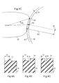
- This figure shows the longitudinal profile 30, as well as the inner 32 and outer 33 profiles of the grinding wheel used to cut the ophthalmic lens (typically the bevel grinding wheel 213 or the grinding wheel 221).
- the outer profile 33 corresponds to the general profile of the grinding wheel
- the inner profile 32 corresponds to the profile of the bottom of the beveling groove of this grinding wheel.
- the creasing wheel 221 the outer profile 33 corresponds to the general profile of the creasing wheel
- the inner profile 32 corresponds to the profile of the nonactive part of this grinding wheel (that is, to say of the part which does not take part in the machining of the lens, considering the depth of depression of the grinding wheel in the edge of the lens).
- the radius of the outer profile 33 is noted R m while the gap between the inner 32 and outer 33 profiles is noted ⁇ P.
- this point of intersection corresponds to the final singular point P2 '.
- the control unit 10 defines a first final arc D1 ', referred to in the final upper arc example, corresponding to the part of the longitudinal profile 30 which is delimited between these two final singular points P1 ',', P2 '.
- This final upper arc D1 ' has a reduced length compared to that of the upper initial arc D1.
- the lower arc D2 remains defined as being that delimited between the two initial singular points P1, P2, so that the final lower arc D1 'and the upper arc D2 are no longer complementary.
- the control unit 251 controls the various degrees of freedom of the grinder 200 in a manner. to reduce coarsely the rays of the ophthalmic lens 10 previously locked between the clamping shafts 202, 203 of the grinder 200.
- the blank wheel 215 and the rocker 201 are driven relative to each other so as to reduce, for each angular position of the lens around the locking pin A7, the radius of the lens to a radius of length strictly greater than that of the corresponding radius of the longitudinal profile 30.
- control unit 251 controls the various degrees of freedom of the grinder 200 so as to bring back an upper portion E1 (see FIG. figure 9 ) of the contour of the lens to the shape of the first final arc D1 'of the longitudinal profile 30.
- control unit 251 controls the various degrees of freedom of the grinder 200 so as to bring a lower portion E2 of the contour of the lens to the shape of the second arc D2 longitudinal profile 30.
- first and second finishing steps are carried out so that the finishes (bevel 11, groove 12-13, flat finish 14) are different on the two parts E1, E2 of the contour of the ophthalmic lens 10
- the first finishing step is performed on the entire contour of the ophthalmic lens, while the second finishing step is performed on only a portion of the lens contour, that complementary to the upper portion E1.
- these finishes 11, 12, 13 are preferably made so that their mean lines extend at the same constant distance C1 from the front face of the ophthalmic lens 10.
- the wafer of the ophthalmic lens 10 is polished using the polishing wheels 211, 212 of the grinder 200.
- the first finishing step must then consist of a beveling operation of the upper portion E1 of the contour of the ophthalmic lens 10, while the second finishing step must consist of two grinding and creasing operations of the lower part E2 of the contour of the ophthalmic lens 10.
- the entire contour of the ophthalmic lens 10 is bevelled following a profile composed of the arches D1 '- D3 - D4 which is partly distinct from the longitudinal profile 30.
- the beveling grinding wheel 213 is more precisely controlled relative to the ophthalmic lens 10 so that the bottom of its bevelling groove 213A follows a profile which is merged with the final upper arc D1 of the longitudinal profile 30, but which is distinct from the lower arch D2.
- This arc D4 is distinguished here from the lower arc D2 in that it is spaced radially thereof from the boxing center O1 a constant F1 difference.
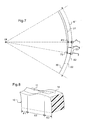
- This difference F1 is here chosen equal to the depth F2 of the beveling groove 213A of the beveling wheel ( figure 2 ).
- the ophthalmic lens 10 is bevelled following an arc of link D3 which extends from the final upper arc D1 'to the arc D4, thus deviating radially from the longitudinal profile 30.
- connection part E3 the contour of the ophthalmic lens 10 thus forms a rounded step which is progressive and continuous, the length of curvilinear abscissa is related to the value of the offset angle THETA1, THETA2 and whose height is equal to the depth F2 of the beveling groove 213A of the beveling wheel 213.
- the right grinding wheel 214 is driven relative to the ophthalmic lens 10 so that its working surface follows the longitudinal profile 30.
- the bevel 11 initially formed is entirely truncated and has a straight finish 14.
- the bevel 11 is partially truncated. Its vertex is thus progressively truncated from the final singular points P1 ', P2' where it is left intact, to the initial singular points P1, P2 where the bevel is entirely truncated.
- the height of the bevel 11 thus varies progressively on each of the connection portions E3 of the contour of the ophthalmic lens 10.
- the creasing wheel 221 is driven relative to the ophthalmic lens 10 so that, on the lower part E2 of the contour of the lens, its working surface follows an arc D6 which is radially spaced from the lower arc D2, the inner side of the longitudinal profile 30, a constant F3 gap.
- the creasing wheel 221 is thus controlled in the lower part E2 of the contour of the lens so that its working surface penetrates a desired depth F3 into the edge of the ophthalmic lens 10.
- the creasing wheel 221 is moreover controlled, on the connection portions E3 of the lens contour, in such a way that its working surface progressively deviates from the ophthalmic lens 10.
- each connecting portion E3 It is more precisely controlled, on each of these connecting portions E3, following an arc D5 which extends from the corresponding end of the arc D6 to the corresponding end of the final upper arc D1 '.
- the depth of the groove 13 obtained varies progressively along each connecting portion E3 of the lens contour, from a maximum depth F3 at the initial singular points P1, P2 to a zero depth at the final singular points P1 ', P2'.
- the non-truncated portion of the bevel 11 machined on the edge of the ophthalmic lens 10 extends over an angular sector of the contour of the ophthalmic lens which is smaller than the angular sector of the arcade of the eyeglass frame 20. In this way , the bevel 11 does not appear unsightly at the ends of the arcade of the spectacle frame 20.
- the groove 13 engages under the arcade of the eyeglass frame 20, so that the nylon thread 21A hooked close to this end of the arch may engage directly in the groove 13 without abutting against the edge of the ophthalmic lens 10, to the benefit of the aesthetics of the pair of spectacles thus obtained and the rigidity of the mounting of the ophthalmic lens 10 in its surroundings 21.
- the first finishing step must then consist of a bevelling operation of a first portion E1 of the contour of the ophthalmic lens 10, while the second finishing step must consist of a single operation of rectification of a second portion E2 of the contour of the ophthalmic lens 10.
- the first finishing step must then consist of a grinding operation ( figure 11A ) followed by a first creasing operation ( figure 11 B) a first portion E1 of the contour of the ophthalmic lens 10, to form a first groove 13 of given width and depth.
- the second finishing step must consist of a second creasing operation ( figure 11 C) a second portion E2 of the contour of the ophthalmic lens 10, to form a second groove 12 of width and / or depth different (s) from that (s) of the first groove 13.
- the entire contour of the ophthalmic lens 10 is ground according to the longitudinal profile 30.
- the right grinding wheel 214 is more precisely controlled relative to the ophthalmic lens 10 so that its working surface follows the entire longitudinal profile 30.
- the entire contour of the ophthalmic lens 10 is slotted so that the first groove 13 extends over the entire slice of the lens.
- the creasing wheel 221 is driven relative to the ophthalmic lens 10 so that its working surface follows a profile which is spaced radially from the longitudinal profile 30 by a constant value, chosen as a function of the desired depth. for the first groove 13.
- the creasing wheel 221 is then driven relative to the ophthalmic lens 10 so that its working surface returns to the portion of the first groove 13 which is located along the final upper arch D1 '.
- the creasing wheel 221 is more precisely controlled to crosswise transversely to widen the first groove 13 so as to form the second groove 12.
- the ophthalmic lens is slotted so that the junctions between its two grooves are abrupt and thus form two narrowing sections at the two final singular points P1 ', P2'.
- each groove 12, 13 to be adapted to the diameter of the nylon thread and the width of the rib provided along the inner face of the arcade of the spectacle frame.
Landscapes
- Engineering & Computer Science (AREA)
- Mechanical Engineering (AREA)
- Chemical & Material Sciences (AREA)
- Ceramic Engineering (AREA)
- Inorganic Chemistry (AREA)
- Eyeglasses (AREA)
- Grinding And Polishing Of Tertiary Curved Surfaces And Surfaces With Complex Shapes (AREA)
Applications Claiming Priority (1)
| Application Number | Priority Date | Filing Date | Title |
|---|---|---|---|
| FR1003565A FR2964336B1 (fr) | 2010-09-07 | 2010-09-07 | Procede de detourage d'une lentille ophtalmique |
Publications (2)
| Publication Number | Publication Date |
|---|---|
| EP2425926A1 true EP2425926A1 (de) | 2012-03-07 |
| EP2425926B1 EP2425926B1 (de) | 2013-01-09 |
Family
ID=44124891
Family Applications (1)
| Application Number | Title | Priority Date | Filing Date |
|---|---|---|---|
| EP20110290347 Active EP2425926B1 (de) | 2010-09-07 | 2011-07-28 | Konturfräsverfahren einer Augenlinse |
Country Status (3)
| Country | Link |
|---|---|
| US (1) | US8926401B2 (de) |
| EP (1) | EP2425926B1 (de) |
| FR (1) | FR2964336B1 (de) |
Cited By (1)
| Publication number | Priority date | Publication date | Assignee | Title |
|---|---|---|---|---|
| US20210308971A1 (en) * | 2018-05-09 | 2021-10-07 | Essilor International | Method for manufacturing an ophthalmic lens to be mounted in a frame, ophthalmic lens, frame and eyeglasses equipment |
Families Citing this family (4)
| Publication number | Priority date | Publication date | Assignee | Title |
|---|---|---|---|---|
| JP6034582B2 (ja) * | 2012-03-29 | 2016-11-30 | Hoya株式会社 | 眼鏡レンズの製造方法、周長算出装置および周長算出プログラム |
| FR2990369B1 (fr) * | 2012-05-09 | 2014-08-29 | Essilor Int | Procede de detourage d'une lentille ophtalmique multicouche |
| US10748091B1 (en) | 2020-01-16 | 2020-08-18 | Applied Underwriters, Inc. | Forecasting digital reservoir controller |
| EP4001998A1 (de) | 2020-11-20 | 2022-05-25 | Essilor International | System und verfahren zum kanten von ophthalmischen linsen |
Citations (3)
| Publication number | Priority date | Publication date | Assignee | Title |
|---|---|---|---|---|
| US5347762A (en) * | 1992-02-04 | 1994-09-20 | Nidek Co., Ltd. | Lens periphery processing apparatus, method for obtaining processing data, and lens periphery processing method |
| EP1266722A1 (de) | 2000-06-15 | 2002-12-18 | Nidek Co., Ltd. | Vorrichtung zur Bearbeitung von Brillengläsern |
| EP1815941A1 (de) * | 2006-02-03 | 2007-08-08 | Nidek Co., Ltd | Vorrichtung zum Bearbeiten von Brillengläsern |
Family Cites Families (6)
| Publication number | Priority date | Publication date | Assignee | Title |
|---|---|---|---|---|
| US6884154B2 (en) * | 2000-02-23 | 2005-04-26 | Shin-Etsu Handotai Co., Ltd. | Method for apparatus for polishing outer peripheral chamfered part of wafer |
| US6758733B2 (en) * | 2002-03-13 | 2004-07-06 | Ronald C. Wiand | Two-part beveling wheel for improved positioning of bevel contours on ophthalmic lenses |
| FR2907041B1 (fr) * | 2006-10-13 | 2008-12-26 | Essilor Int | Procede de detourage d'une lentille ophtalmique |
| FR2912335B1 (fr) * | 2007-02-13 | 2009-04-17 | Essilor Int | Machine de detourage d'une lentille de lunettes,pourvue d'un porte-outils tournant sur lequel sont montes plusieurs outils de travail |
| FR2926896B1 (fr) * | 2008-01-28 | 2010-03-19 | Essilor Int | Procede de preparation d'une lentille ophtlmique avec usinage specifique de sa nervure d'emboitement |
| FR2962676B1 (fr) * | 2010-07-13 | 2012-08-03 | Essilor Int | Procede de detourage d'une lentille ophtalmique de lunettes comportant un film de revetement. |
-
2010
- 2010-09-07 FR FR1003565A patent/FR2964336B1/fr not_active Expired - Fee Related
-
2011
- 2011-07-28 EP EP20110290347 patent/EP2425926B1/de active Active
- 2011-09-01 US US13/223,401 patent/US8926401B2/en active Active
Patent Citations (3)
| Publication number | Priority date | Publication date | Assignee | Title |
|---|---|---|---|---|
| US5347762A (en) * | 1992-02-04 | 1994-09-20 | Nidek Co., Ltd. | Lens periphery processing apparatus, method for obtaining processing data, and lens periphery processing method |
| EP1266722A1 (de) | 2000-06-15 | 2002-12-18 | Nidek Co., Ltd. | Vorrichtung zur Bearbeitung von Brillengläsern |
| EP1815941A1 (de) * | 2006-02-03 | 2007-08-08 | Nidek Co., Ltd | Vorrichtung zum Bearbeiten von Brillengläsern |
Cited By (2)
| Publication number | Priority date | Publication date | Assignee | Title |
|---|---|---|---|---|
| US20210308971A1 (en) * | 2018-05-09 | 2021-10-07 | Essilor International | Method for manufacturing an ophthalmic lens to be mounted in a frame, ophthalmic lens, frame and eyeglasses equipment |
| US11787136B2 (en) * | 2018-05-09 | 2023-10-17 | Essilor International | Method for manufacturing an ophthalmic lens to be mounted in a frame, ophthalmic lens, frame and eyeglasses equipment |
Also Published As
| Publication number | Publication date |
|---|---|
| EP2425926B1 (de) | 2013-01-09 |
| FR2964336A1 (fr) | 2012-03-09 |
| FR2964336B1 (fr) | 2012-09-14 |
| US8926401B2 (en) | 2015-01-06 |
| US20120058714A1 (en) | 2012-03-08 |
Similar Documents
| Publication | Publication Date | Title |
|---|---|---|
| EP2046529B1 (de) | Brillenglaspaar und verfahren zur formung einer peripheren fassungsrippe auf der kante eines brillenglases | |
| EP2076358B1 (de) | Vorrichtung zur bearbeitung von brillengläsern mit mehreren auf einem ausrichtbaren modul positionierten maschinenwerkzeugen | |
| EP1807244B1 (de) | Vorrichtung und verfahren zum einstellen der bohrrichtung eines bohrwerkzeugs für eine ophthalmische linse | |
| EP2410372B1 (de) | Berechnungsverfahren eines Sollwerts zum Facetten- oder Rillenschleifen einer Sehlinse | |
| EP2425926B1 (de) | Konturfräsverfahren einer Augenlinse | |
| EP2210703B1 (de) | Brillenglasbearbeitungsvorrichtung | |
| EP2247407B1 (de) | Verfahren zur herstellung einer kontaktlinse mit besonderer verarbeitung von deren fassungsrippe | |
| EP2760631B1 (de) | Verfahren zum konturfräsen eines brillenglases | |
| EP2268997B1 (de) | Vorrichtung und verfahren zum erfassen der geometrie der glasseinfassung eines brillengestells | |
| FR2893524A1 (fr) | Procede et dispositif de detourage d'une lentille ophtalmique pour usiner le chant de la lentille suivant une courbe voulue | |
| EP2234758B9 (de) | Verfahren zur herstellung einer kontaktlinse mit besonderer verarbeitung von deren fassungsrippe | |
| FR3008914A1 (fr) | Procede et machine de gravure de lentilles optiques | |
| CA2904024C (fr) | Dispositif de detourage de lentilles ophtalmiques | |
| FR2887168A1 (fr) | Procede et dispositif de detourage biseaute d'une lentille ophtalmique de lunettes | |
| EP2846969B1 (de) | Verfahren zum ausschneiden einer mehrschichtigen ophthalmische linse | |
| EP2247408B1 (de) | Sichtgerät mit brillenglas mit teilweise beschnittener einsatzrippe und verfahren zur herstellung eines derartigen glases | |
| EP2253427B1 (de) | Vorrichtung und Verfahren zur Vorbereitung der Montage einer ophthalmischen Brillenlinse | |
| EP2399709B1 (de) | Rechnerisches Simulationsverfahren zur Gestaltung einer peripheren Fassungsrippe auf der Kante eines Brillenglases und Verfahren des Facettierens | |
| WO2006045965A1 (fr) | Procede de finition ou de retouche de detourage de la peripherie d'une lentille ophtalmique selon un chant profile |
Legal Events
| Date | Code | Title | Description |
|---|---|---|---|
| AK | Designated contracting states |
Kind code of ref document: A1 Designated state(s): AL AT BE BG CH CY CZ DE DK EE ES FI FR GB GR HR HU IE IS IT LI LT LU LV MC MK MT NL NO PL PT RO RS SE SI SK SM TR |
|
| AX | Request for extension of the european patent |
Extension state: BA ME |
|
| PUAI | Public reference made under article 153(3) epc to a published international application that has entered the european phase |
Free format text: ORIGINAL CODE: 0009012 |
|
| 17P | Request for examination filed |
Effective date: 20120712 |
|
| GRAP | Despatch of communication of intention to grant a patent |
Free format text: ORIGINAL CODE: EPIDOSNIGR1 |
|
| RIC1 | Information provided on ipc code assigned before grant |
Ipc: B24B 9/14 20060101AFI20120731BHEP Ipc: G02C 13/00 20060101ALI20120731BHEP Ipc: B24B 51/00 20060101ALI20120731BHEP |
|
| RIN1 | Information on inventor provided before grant (corrected) |
Inventor name: BATHEROSSE, ROMAIN Inventor name: LEMAIRE, CEDRIC |
|
| GRAS | Grant fee paid |
Free format text: ORIGINAL CODE: EPIDOSNIGR3 |
|
| GRAA | (expected) grant |
Free format text: ORIGINAL CODE: 0009210 |
|
| AK | Designated contracting states |
Kind code of ref document: B1 Designated state(s): AL AT BE BG CH CY CZ DE DK EE ES FI FR GB GR HR HU IE IS IT LI LT LU LV MC MK MT NL NO PL PT RO RS SE SI SK SM TR |
|
| REG | Reference to a national code |
Ref country code: GB Ref legal event code: FG4D Free format text: NOT ENGLISH |
|
| REG | Reference to a national code |
Ref country code: CH Ref legal event code: EP Ref country code: AT Ref legal event code: REF Ref document number: 592454 Country of ref document: AT Kind code of ref document: T Effective date: 20130115 |
|
| REG | Reference to a national code |
Ref country code: IE Ref legal event code: FG4D Free format text: LANGUAGE OF EP DOCUMENT: FRENCH |
|
| REG | Reference to a national code |
Ref country code: DE Ref legal event code: R096 Ref document number: 602011000721 Country of ref document: DE Effective date: 20130307 |
|
| PG25 | Lapsed in a contracting state [announced via postgrant information from national office to epo] |
Ref country code: SI Free format text: LAPSE BECAUSE OF FAILURE TO SUBMIT A TRANSLATION OF THE DESCRIPTION OR TO PAY THE FEE WITHIN THE PRESCRIBED TIME-LIMIT Effective date: 20130109 |
|
| REG | Reference to a national code |
Ref country code: NL Ref legal event code: VDEP Effective date: 20130109 |
|
| REG | Reference to a national code |
Ref country code: AT Ref legal event code: MK05 Ref document number: 592454 Country of ref document: AT Kind code of ref document: T Effective date: 20130109 |
|
| REG | Reference to a national code |
Ref country code: LT Ref legal event code: MG4D |
|
| PG25 | Lapsed in a contracting state [announced via postgrant information from national office to epo] |
Ref country code: AT Free format text: LAPSE BECAUSE OF FAILURE TO SUBMIT A TRANSLATION OF THE DESCRIPTION OR TO PAY THE FEE WITHIN THE PRESCRIBED TIME-LIMIT Effective date: 20130109 Ref country code: ES Free format text: LAPSE BECAUSE OF FAILURE TO SUBMIT A TRANSLATION OF THE DESCRIPTION OR TO PAY THE FEE WITHIN THE PRESCRIBED TIME-LIMIT Effective date: 20130420 Ref country code: IS Free format text: LAPSE BECAUSE OF FAILURE TO SUBMIT A TRANSLATION OF THE DESCRIPTION OR TO PAY THE FEE WITHIN THE PRESCRIBED TIME-LIMIT Effective date: 20130509 Ref country code: BG Free format text: LAPSE BECAUSE OF FAILURE TO SUBMIT A TRANSLATION OF THE DESCRIPTION OR TO PAY THE FEE WITHIN THE PRESCRIBED TIME-LIMIT Effective date: 20130409 Ref country code: SE Free format text: LAPSE BECAUSE OF FAILURE TO SUBMIT A TRANSLATION OF THE DESCRIPTION OR TO PAY THE FEE WITHIN THE PRESCRIBED TIME-LIMIT Effective date: 20130109 Ref country code: NO Free format text: LAPSE BECAUSE OF FAILURE TO SUBMIT A TRANSLATION OF THE DESCRIPTION OR TO PAY THE FEE WITHIN THE PRESCRIBED TIME-LIMIT Effective date: 20130409 Ref country code: LT Free format text: LAPSE BECAUSE OF FAILURE TO SUBMIT A TRANSLATION OF THE DESCRIPTION OR TO PAY THE FEE WITHIN THE PRESCRIBED TIME-LIMIT Effective date: 20130109 |
|
| PG25 | Lapsed in a contracting state [announced via postgrant information from national office to epo] |
Ref country code: LV Free format text: LAPSE BECAUSE OF FAILURE TO SUBMIT A TRANSLATION OF THE DESCRIPTION OR TO PAY THE FEE WITHIN THE PRESCRIBED TIME-LIMIT Effective date: 20130109 Ref country code: FI Free format text: LAPSE BECAUSE OF FAILURE TO SUBMIT A TRANSLATION OF THE DESCRIPTION OR TO PAY THE FEE WITHIN THE PRESCRIBED TIME-LIMIT Effective date: 20130109 Ref country code: PT Free format text: LAPSE BECAUSE OF FAILURE TO SUBMIT A TRANSLATION OF THE DESCRIPTION OR TO PAY THE FEE WITHIN THE PRESCRIBED TIME-LIMIT Effective date: 20130509 Ref country code: PL Free format text: LAPSE BECAUSE OF FAILURE TO SUBMIT A TRANSLATION OF THE DESCRIPTION OR TO PAY THE FEE WITHIN THE PRESCRIBED TIME-LIMIT Effective date: 20130109 Ref country code: GR Free format text: LAPSE BECAUSE OF FAILURE TO SUBMIT A TRANSLATION OF THE DESCRIPTION OR TO PAY THE FEE WITHIN THE PRESCRIBED TIME-LIMIT Effective date: 20130410 Ref country code: NL Free format text: LAPSE BECAUSE OF FAILURE TO SUBMIT A TRANSLATION OF THE DESCRIPTION OR TO PAY THE FEE WITHIN THE PRESCRIBED TIME-LIMIT Effective date: 20130109 |
|
| PG25 | Lapsed in a contracting state [announced via postgrant information from national office to epo] |
Ref country code: HR Free format text: LAPSE BECAUSE OF FAILURE TO SUBMIT A TRANSLATION OF THE DESCRIPTION OR TO PAY THE FEE WITHIN THE PRESCRIBED TIME-LIMIT Effective date: 20130109 Ref country code: RS Free format text: LAPSE BECAUSE OF FAILURE TO SUBMIT A TRANSLATION OF THE DESCRIPTION OR TO PAY THE FEE WITHIN THE PRESCRIBED TIME-LIMIT Effective date: 20130109 |
|
| PG25 | Lapsed in a contracting state [announced via postgrant information from national office to epo] |
Ref country code: SK Free format text: LAPSE BECAUSE OF FAILURE TO SUBMIT A TRANSLATION OF THE DESCRIPTION OR TO PAY THE FEE WITHIN THE PRESCRIBED TIME-LIMIT Effective date: 20130109 Ref country code: EE Free format text: LAPSE BECAUSE OF FAILURE TO SUBMIT A TRANSLATION OF THE DESCRIPTION OR TO PAY THE FEE WITHIN THE PRESCRIBED TIME-LIMIT Effective date: 20130109 Ref country code: DK Free format text: LAPSE BECAUSE OF FAILURE TO SUBMIT A TRANSLATION OF THE DESCRIPTION OR TO PAY THE FEE WITHIN THE PRESCRIBED TIME-LIMIT Effective date: 20130109 Ref country code: CZ Free format text: LAPSE BECAUSE OF FAILURE TO SUBMIT A TRANSLATION OF THE DESCRIPTION OR TO PAY THE FEE WITHIN THE PRESCRIBED TIME-LIMIT Effective date: 20130109 Ref country code: RO Free format text: LAPSE BECAUSE OF FAILURE TO SUBMIT A TRANSLATION OF THE DESCRIPTION OR TO PAY THE FEE WITHIN THE PRESCRIBED TIME-LIMIT Effective date: 20130109 |
|
| PLBE | No opposition filed within time limit |
Free format text: ORIGINAL CODE: 0009261 |
|
| STAA | Information on the status of an ep patent application or granted ep patent |
Free format text: STATUS: NO OPPOSITION FILED WITHIN TIME LIMIT |
|
| PG25 | Lapsed in a contracting state [announced via postgrant information from national office to epo] |
Ref country code: CY Free format text: LAPSE BECAUSE OF FAILURE TO SUBMIT A TRANSLATION OF THE DESCRIPTION OR TO PAY THE FEE WITHIN THE PRESCRIBED TIME-LIMIT Effective date: 20130109 |
|
| 26N | No opposition filed |
Effective date: 20131010 |
|
| PG25 | Lapsed in a contracting state [announced via postgrant information from national office to epo] |
Ref country code: IT Free format text: LAPSE BECAUSE OF FAILURE TO SUBMIT A TRANSLATION OF THE DESCRIPTION OR TO PAY THE FEE WITHIN THE PRESCRIBED TIME-LIMIT Effective date: 20130109 |
|
| REG | Reference to a national code |
Ref country code: DE Ref legal event code: R097 Ref document number: 602011000721 Country of ref document: DE Effective date: 20131010 |
|
| BERE | Be: lapsed |
Owner name: ESSILOR INTERNATIONAL (COMPAGNIE GENERALE D'OPTIQ Effective date: 20130731 |
|
| PG25 | Lapsed in a contracting state [announced via postgrant information from national office to epo] |
Ref country code: MC Free format text: LAPSE BECAUSE OF FAILURE TO SUBMIT A TRANSLATION OF THE DESCRIPTION OR TO PAY THE FEE WITHIN THE PRESCRIBED TIME-LIMIT Effective date: 20130109 |
|
| REG | Reference to a national code |
Ref country code: IE Ref legal event code: MM4A |
|
| PG25 | Lapsed in a contracting state [announced via postgrant information from national office to epo] |
Ref country code: BE Free format text: LAPSE BECAUSE OF NON-PAYMENT OF DUE FEES Effective date: 20130731 |
|
| PG25 | Lapsed in a contracting state [announced via postgrant information from national office to epo] |
Ref country code: IE Free format text: LAPSE BECAUSE OF NON-PAYMENT OF DUE FEES Effective date: 20130728 |
|
| REG | Reference to a national code |
Ref country code: CH Ref legal event code: PL |
|
| PG25 | Lapsed in a contracting state [announced via postgrant information from national office to epo] |
Ref country code: CH Free format text: LAPSE BECAUSE OF NON-PAYMENT OF DUE FEES Effective date: 20140731 Ref country code: LI Free format text: LAPSE BECAUSE OF NON-PAYMENT OF DUE FEES Effective date: 20140731 |
|
| PG25 | Lapsed in a contracting state [announced via postgrant information from national office to epo] |
Ref country code: SM Free format text: LAPSE BECAUSE OF FAILURE TO SUBMIT A TRANSLATION OF THE DESCRIPTION OR TO PAY THE FEE WITHIN THE PRESCRIBED TIME-LIMIT Effective date: 20130109 |
|
| PG25 | Lapsed in a contracting state [announced via postgrant information from national office to epo] |
Ref country code: MT Free format text: LAPSE BECAUSE OF FAILURE TO SUBMIT A TRANSLATION OF THE DESCRIPTION OR TO PAY THE FEE WITHIN THE PRESCRIBED TIME-LIMIT Effective date: 20130109 Ref country code: TR Free format text: LAPSE BECAUSE OF FAILURE TO SUBMIT A TRANSLATION OF THE DESCRIPTION OR TO PAY THE FEE WITHIN THE PRESCRIBED TIME-LIMIT Effective date: 20130109 |
|
| PG25 | Lapsed in a contracting state [announced via postgrant information from national office to epo] |
Ref country code: MK Free format text: LAPSE BECAUSE OF FAILURE TO SUBMIT A TRANSLATION OF THE DESCRIPTION OR TO PAY THE FEE WITHIN THE PRESCRIBED TIME-LIMIT Effective date: 20130109 Ref country code: HU Free format text: LAPSE BECAUSE OF FAILURE TO SUBMIT A TRANSLATION OF THE DESCRIPTION OR TO PAY THE FEE WITHIN THE PRESCRIBED TIME-LIMIT; INVALID AB INITIO Effective date: 20110728 Ref country code: LU Free format text: LAPSE BECAUSE OF NON-PAYMENT OF DUE FEES Effective date: 20130728 |
|
| REG | Reference to a national code |
Ref country code: FR Ref legal event code: PLFP Year of fee payment: 6 |
|
| REG | Reference to a national code |
Ref country code: FR Ref legal event code: PLFP Year of fee payment: 7 |
|
| REG | Reference to a national code |
Ref country code: DE Ref legal event code: R082 Ref document number: 602011000721 Country of ref document: DE Representative=s name: CORALIS PATENTANWAELTE, FR Ref country code: DE Ref legal event code: R081 Ref document number: 602011000721 Country of ref document: DE Owner name: ESSILOR INTERNATIONAL, FR Free format text: FORMER OWNER: ESSILOR INTERNATIONAL (COMPAGNIE GENERALE D'OPTIQUE), CHARENTON-LE-PONT, FR |
|
| REG | Reference to a national code |
Ref country code: FR Ref legal event code: TP Owner name: ESSILOR INTERNATIONAL, FR Effective date: 20180601 |
|
| REG | Reference to a national code |
Ref country code: FR Ref legal event code: PLFP Year of fee payment: 8 |
|
| PG25 | Lapsed in a contracting state [announced via postgrant information from national office to epo] |
Ref country code: AL Free format text: LAPSE BECAUSE OF FAILURE TO SUBMIT A TRANSLATION OF THE DESCRIPTION OR TO PAY THE FEE WITHIN THE PRESCRIBED TIME-LIMIT Effective date: 20130109 |
|
| P01 | Opt-out of the competence of the unified patent court (upc) registered |
Effective date: 20230525 |
|
| PGFP | Annual fee paid to national office [announced via postgrant information from national office to epo] |
Ref country code: GB Payment date: 20230727 Year of fee payment: 13 |
|
| PGFP | Annual fee paid to national office [announced via postgrant information from national office to epo] |
Ref country code: FR Payment date: 20230725 Year of fee payment: 13 Ref country code: DE Payment date: 20230727 Year of fee payment: 13 |