EP1266701B1 - Katalytische Beschichtung von strukturierten Wärmetauschern - Google Patents
Katalytische Beschichtung von strukturierten Wärmetauschern Download PDFInfo
- Publication number
- EP1266701B1 EP1266701B1 EP02011805A EP02011805A EP1266701B1 EP 1266701 B1 EP1266701 B1 EP 1266701B1 EP 02011805 A EP02011805 A EP 02011805A EP 02011805 A EP02011805 A EP 02011805A EP 1266701 B1 EP1266701 B1 EP 1266701B1
- Authority
- EP
- European Patent Office
- Prior art keywords
- process according
- printing
- heat exchanger
- material component
- catalytically active
- Prior art date
- Legal status (The legal status is an assumption and is not a legal conclusion. Google has not performed a legal analysis and makes no representation as to the accuracy of the status listed.)
- Expired - Lifetime
Links
Images

Classifications
-
- F—MECHANICAL ENGINEERING; LIGHTING; HEATING; WEAPONS; BLASTING
- F28—HEAT EXCHANGE IN GENERAL
- F28F—DETAILS OF HEAT-EXCHANGE AND HEAT-TRANSFER APPARATUS, OF GENERAL APPLICATION
- F28F3/00—Plate-like or laminated elements; Assemblies of plate-like or laminated elements
- F28F3/02—Elements or assemblies thereof with means for increasing heat-transfer area, e.g. with fins, with recesses, with corrugations
- F28F3/04—Elements or assemblies thereof with means for increasing heat-transfer area, e.g. with fins, with recesses, with corrugations the means being integral with the element
- F28F3/042—Elements or assemblies thereof with means for increasing heat-transfer area, e.g. with fins, with recesses, with corrugations the means being integral with the element in the form of local deformations of the element
- F28F3/046—Elements or assemblies thereof with means for increasing heat-transfer area, e.g. with fins, with recesses, with corrugations the means being integral with the element in the form of local deformations of the element the deformations being linear, e.g. corrugations
-
- B—PERFORMING OPERATIONS; TRANSPORTING
- B01—PHYSICAL OR CHEMICAL PROCESSES OR APPARATUS IN GENERAL
- B01J—CHEMICAL OR PHYSICAL PROCESSES, e.g. CATALYSIS OR COLLOID CHEMISTRY; THEIR RELEVANT APPARATUS
- B01J19/00—Chemical, physical or physico-chemical processes in general; Their relevant apparatus
- B01J19/24—Stationary reactors without moving elements inside
- B01J19/248—Reactors comprising multiple separated flow channels
- B01J19/249—Plate-type reactors
-
- F—MECHANICAL ENGINEERING; LIGHTING; HEATING; WEAPONS; BLASTING
- F28—HEAT EXCHANGE IN GENERAL
- F28D—HEAT-EXCHANGE APPARATUS, NOT PROVIDED FOR IN ANOTHER SUBCLASS, IN WHICH THE HEAT-EXCHANGE MEDIA DO NOT COME INTO DIRECT CONTACT
- F28D9/00—Heat-exchange apparatus having stationary plate-like or laminated conduit assemblies for both heat-exchange media, the media being in contact with different sides of a conduit wall
- F28D9/0031—Heat-exchange apparatus having stationary plate-like or laminated conduit assemblies for both heat-exchange media, the media being in contact with different sides of a conduit wall the conduits for one heat-exchange medium being formed by paired plates touching each other
- F28D9/0043—Heat-exchange apparatus having stationary plate-like or laminated conduit assemblies for both heat-exchange media, the media being in contact with different sides of a conduit wall the conduits for one heat-exchange medium being formed by paired plates touching each other the plates having openings therein for circulation of at least one heat-exchange medium from one conduit to another
- F28D9/005—Heat-exchange apparatus having stationary plate-like or laminated conduit assemblies for both heat-exchange media, the media being in contact with different sides of a conduit wall the conduits for one heat-exchange medium being formed by paired plates touching each other the plates having openings therein for circulation of at least one heat-exchange medium from one conduit to another the plates having openings therein for both heat-exchange media
-
- H—ELECTRICITY
- H01—ELECTRIC ELEMENTS
- H01M—PROCESSES OR MEANS, e.g. BATTERIES, FOR THE DIRECT CONVERSION OF CHEMICAL ENERGY INTO ELECTRICAL ENERGY
- H01M8/00—Fuel cells; Manufacture thereof
- H01M8/06—Combination of fuel cells with means for production of reactants or for treatment of residues
- H01M8/0606—Combination of fuel cells with means for production of reactants or for treatment of residues with means for production of gaseous reactants
- H01M8/0612—Combination of fuel cells with means for production of reactants or for treatment of residues with means for production of gaseous reactants from carbon-containing material
- H01M8/0625—Combination of fuel cells with means for production of reactants or for treatment of residues with means for production of gaseous reactants from carbon-containing material in a modular combined reactor/fuel cell structure
- H01M8/0631—Reactor construction specially adapted for combination reactor/fuel cell
-
- B—PERFORMING OPERATIONS; TRANSPORTING
- B01—PHYSICAL OR CHEMICAL PROCESSES OR APPARATUS IN GENERAL
- B01J—CHEMICAL OR PHYSICAL PROCESSES, e.g. CATALYSIS OR COLLOID CHEMISTRY; THEIR RELEVANT APPARATUS
- B01J2219/00—Chemical, physical or physico-chemical processes in general; Their relevant apparatus
- B01J2219/24—Stationary reactors without moving elements inside
- B01J2219/2401—Reactors comprising multiple separate flow channels
- B01J2219/245—Plate-type reactors
- B01J2219/2451—Geometry of the reactor
- B01J2219/2456—Geometry of the plates
- B01J2219/2458—Flat plates, i.e. plates which are not corrugated or otherwise structured, e.g. plates with cylindrical shape
-
- B—PERFORMING OPERATIONS; TRANSPORTING
- B01—PHYSICAL OR CHEMICAL PROCESSES OR APPARATUS IN GENERAL
- B01J—CHEMICAL OR PHYSICAL PROCESSES, e.g. CATALYSIS OR COLLOID CHEMISTRY; THEIR RELEVANT APPARATUS
- B01J2219/00—Chemical, physical or physico-chemical processes in general; Their relevant apparatus
- B01J2219/24—Stationary reactors without moving elements inside
- B01J2219/2401—Reactors comprising multiple separate flow channels
- B01J2219/245—Plate-type reactors
- B01J2219/2451—Geometry of the reactor
- B01J2219/2456—Geometry of the plates
- B01J2219/2459—Corrugated plates
-
- B—PERFORMING OPERATIONS; TRANSPORTING
- B01—PHYSICAL OR CHEMICAL PROCESSES OR APPARATUS IN GENERAL
- B01J—CHEMICAL OR PHYSICAL PROCESSES, e.g. CATALYSIS OR COLLOID CHEMISTRY; THEIR RELEVANT APPARATUS
- B01J2219/00—Chemical, physical or physico-chemical processes in general; Their relevant apparatus
- B01J2219/24—Stationary reactors without moving elements inside
- B01J2219/2401—Reactors comprising multiple separate flow channels
- B01J2219/245—Plate-type reactors
- B01J2219/2461—Heat exchange aspects
-
- B—PERFORMING OPERATIONS; TRANSPORTING
- B01—PHYSICAL OR CHEMICAL PROCESSES OR APPARATUS IN GENERAL
- B01J—CHEMICAL OR PHYSICAL PROCESSES, e.g. CATALYSIS OR COLLOID CHEMISTRY; THEIR RELEVANT APPARATUS
- B01J2219/00—Chemical, physical or physico-chemical processes in general; Their relevant apparatus
- B01J2219/24—Stationary reactors without moving elements inside
- B01J2219/2401—Reactors comprising multiple separate flow channels
- B01J2219/245—Plate-type reactors
- B01J2219/2476—Construction materials
- B01J2219/2477—Construction materials of the catalysts
- B01J2219/2479—Catalysts coated on the surface of plates or inserts
-
- B—PERFORMING OPERATIONS; TRANSPORTING
- B05—SPRAYING OR ATOMISING IN GENERAL; APPLYING FLUENT MATERIALS TO SURFACES, IN GENERAL
- B05D—PROCESSES FOR APPLYING FLUENT MATERIALS TO SURFACES, IN GENERAL
- B05D1/00—Processes for applying liquids or other fluent materials
- B05D1/28—Processes for applying liquids or other fluent materials performed by transfer from the surfaces of elements carrying the liquid or other fluent material, e.g. brushes, pads, rollers
-
- H—ELECTRICITY
- H01—ELECTRIC ELEMENTS
- H01M—PROCESSES OR MEANS, e.g. BATTERIES, FOR THE DIRECT CONVERSION OF CHEMICAL ENERGY INTO ELECTRICAL ENERGY
- H01M8/00—Fuel cells; Manufacture thereof
- H01M8/04—Auxiliary arrangements, e.g. for control of pressure or for circulation of fluids
- H01M8/04007—Auxiliary arrangements, e.g. for control of pressure or for circulation of fluids related to heat exchange
- H01M8/04067—Heat exchange or temperature measuring elements, thermal insulation, e.g. heat pipes, heat pumps, fins
- H01M8/04074—Heat exchange unit structures specially adapted for fuel cell
-
- Y—GENERAL TAGGING OF NEW TECHNOLOGICAL DEVELOPMENTS; GENERAL TAGGING OF CROSS-SECTIONAL TECHNOLOGIES SPANNING OVER SEVERAL SECTIONS OF THE IPC; TECHNICAL SUBJECTS COVERED BY FORMER USPC CROSS-REFERENCE ART COLLECTIONS [XRACs] AND DIGESTS
- Y02—TECHNOLOGIES OR APPLICATIONS FOR MITIGATION OR ADAPTATION AGAINST CLIMATE CHANGE
- Y02E—REDUCTION OF GREENHOUSE GAS [GHG] EMISSIONS, RELATED TO ENERGY GENERATION, TRANSMISSION OR DISTRIBUTION
- Y02E60/00—Enabling technologies; Technologies with a potential or indirect contribution to GHG emissions mitigation
- Y02E60/30—Hydrogen technology
- Y02E60/50—Fuel cells
-
- Y—GENERAL TAGGING OF NEW TECHNOLOGICAL DEVELOPMENTS; GENERAL TAGGING OF CROSS-SECTIONAL TECHNOLOGIES SPANNING OVER SEVERAL SECTIONS OF THE IPC; TECHNICAL SUBJECTS COVERED BY FORMER USPC CROSS-REFERENCE ART COLLECTIONS [XRACs] AND DIGESTS
- Y02—TECHNOLOGIES OR APPLICATIONS FOR MITIGATION OR ADAPTATION AGAINST CLIMATE CHANGE
- Y02P—CLIMATE CHANGE MITIGATION TECHNOLOGIES IN THE PRODUCTION OR PROCESSING OF GOODS
- Y02P70/00—Climate change mitigation technologies in the production process for final industrial or consumer products
- Y02P70/50—Manufacturing or production processes characterised by the final manufactured product
-
- Y—GENERAL TAGGING OF NEW TECHNOLOGICAL DEVELOPMENTS; GENERAL TAGGING OF CROSS-SECTIONAL TECHNOLOGIES SPANNING OVER SEVERAL SECTIONS OF THE IPC; TECHNICAL SUBJECTS COVERED BY FORMER USPC CROSS-REFERENCE ART COLLECTIONS [XRACs] AND DIGESTS
- Y10—TECHNICAL SUBJECTS COVERED BY FORMER USPC
- Y10T—TECHNICAL SUBJECTS COVERED BY FORMER US CLASSIFICATION
- Y10T29/00—Metal working
- Y10T29/49—Method of mechanical manufacture
- Y10T29/4935—Heat exchanger or boiler making
Definitions
- the invention relates to a method for producing a coated, structured heat exchanger plate for a reactor in a fuel cell system.
- DE 199 10 773 A1 describes a method for applying electrode layers to a band-shaped polymer electrolyte membrane for fuel cells.
- the front and back of the membrane are continuously printed in the desired pattern with the electrode layers using an electrocatalyst-containing ink.
- the printed electrode layers are dried immediately after the printing operation at elevated temperature, wherein the printing takes place in compliance with a positionally accurate arrangement of the patterns of the electrode layers of front and back.
- the printing process performed here on a flat surface can also be carried out by tampon printing in addition to stencil, offset or screen printing.
- structured heat exchanger plates for applying coatings are usually spray, rinse or dip coated. In spray coating, however, a coating mass loss of up to 50% occurs due to overspray.
- structured heat exchangers made of spray-coated metal sheets, which are coated over the entire surface layer flaking occurs at the points of contact. If such welded reactors are sputtered or dip-coated, deposits form on the contact points, which also flake off easily when thermal stresses occur.
- the object of the invention is therefore to provide a cost-effective method for coating a structured heat exchanger plate for a rector, in which a catalyst discharge by mechanical and / or thermal stress in the production or operation of a fuel cell system is almost avoided.
- the present invention provides a method for producing a coated, structured heat exchanger plate for a reactor in a fuel cell system with the features of claim 1.
- the further subclaims contain advantageous embodiments of the invention.
- a catalytic component is applied in at least one layer in a continuous or discontinuous manner by pad printing exclusively in the wells 2 and / or flanks 3 of the heat exchanger plate 1.
- the surface of the raised parts 4 of the heat exchanger plate are thus recessed by the coating.
- Pad printing is an indirect printing process, ie a plate called a cliche serves as a template on which the print image is present as a depression.
- the cliché is flooded by means of a doctor blade with a so-called printing paste or printing fluid, which is then withdrawn with a knife again.
- a smooth, elastic stamp called Tampon 6, preferably made of silicone rubber, takes by pressing a portion of this coating composition Due to the elasticity of the silicone rubber, the tampon 6 can, as shown in Fig. 3, adapt to the object to be printed in the discharge of the printing paste or printing fluid to the object to be printed. Characterized the printing of non-planar, structured sheets is possible in which advantageously only the wells 2 and / or flanks 3, but not the raised surfaces 4 of the structured sheet 1 to be printed.
- the coating of the heat exchanger plate with the catalytic component can be carried out by one or more imprints in the total circumference of the sheet.
- the coating can also be done by zonewise coating the heat exchanger plates. Due to the multiple pressure, the individual layers can be functionalized, so that, for example, applied at the reactor inlet another catalyst as at the reactor outlet, on the other hand over the sheet length, the amount of catalyst to build a gradient can be varied. In both of these cases, this procedure serves to selectively control conversions and reactions within the reactor. If one wanted to carry out this procedure by means of spray coating, complex masking of the respective zones would be necessary. In addition to the overspray effect, this would make the method unnecessarily expensive and relatively expensive.
- the applied by pad printing catalytic component contains a catalytically active and / or a water-repellent material component.
- the coating with the respective material components can take place in mixed form or as a single layer, i.
- the catalytically active lower layer and then a top layer containing the water-repellent material component are first printed onto the metal sheet.
- the pad printing can not be applied in sheet form, but in the form of patterns, the first order of the catalytically active material component is not fully covered by the subsequent imprint of the water-repellent material component, so that the reaction gases and / or vapors can still reach the catalyst and so that the catalytic activity is maintained, but a "flooding of the catalyst", ie a complete occupancy of the catalyst with droplets and / or a liquid film by condensation of water vapor and the concomitant decrease in activity or deactivation of the catalyst is avoided.
- the composite of the catalytically active with the water-repellent material component ensures that the catalyst is not hindered by condensation in cold spots in the fuel cell system in its reactivity, but is mainly available for cold start largely available, on the other hand prevents this bond by gluing and / or crosslinking advantageously a chipping or the discharge of the catalyst or reduces these effects as far as possible.
- metals selected from the subgroups of the Periodic Table Ib, IIb, VIIb and / or VIIIb are preferably selected as the catalytically active material, it additionally being possible to include substances which are based on elements from other groups of the periodic table such as oxides of rare earths for thermal stabilization of the catalyst.
- the at least one catalyst material component and / or catalyst-containing Material component is preferably supported.
- support materials for catalysts such as ceramic, carbon, plastic, metal, etc.
- Ceramic materials such as zeolites, Al 2 O 3 , SiO 2 , ZrO 2 , CeO 2 and / or mixtures thereof are particularly preferably used as support materials.
- the at least one water-repellent material preferably contains silicones or silicone-containing materials, fluorinated polymers such as e.g. Polytetrafluoroethylene or polytetrafluoroethylene-containing materials, epoxy resin or epoxy resin-containing materials, phenolic resin or phenolic resin-containing materials, acrylic or acrylic resin-containing materials, polyurethane adhesive materials or polyurethane-containing materials or resin / shellac mixtures or resin-containing / shellac-containing mixtures.
- fluorinated polymers is particularly suitable polytetrafluoroethylene (PTFE) as a water-repellent component and binder for catalysts.
- silicone resins which have to have a high long-term heat resistance in the area of use.
- These use temperatures are in the range between about 30 ° C to 650 ° C, preferably in the range between about 50 ° C to 300 ° C.
- the layer containing the water-repellent material component has an elasticity due to the chemical substance itself, which additionally prevents or substantially reduces the effects of spalling or the discharge of catalyst from the layer.
- the water-repellent material component By networking the water-repellent material component it also acts as a binder for the catalyst.
- the proportion of water-repellent material component with respect to the catalytically active material component and / or catalyst-containing material component is 1 to 50 weight percent, preferably 5 to 25 weight percent.
- the catalyst paste or suspension or liquid required for printing may contain, in addition to at least one catalytically active material component, preferably a ceramic binder which can also be crosslinked after calcination in air at about 500 ° C., and water.
- a ceramic binder which can also be crosslinked after calcination in air at about 500 ° C.
- Particularly suitable as ceramic binders are oxides and / or hydroxides of Al, Ce, Si, Zr and / or mixtures thereof, preference being given to those which can be crosslinked.
- the calcination step is omitted and only one or more drying steps follow.
- An exception to this is the use of PTFE as a polymeric binder, since this material briefly withstands higher temperatures.
- additives such as for controlling the viscosity, wetting behavior on the stamper, or adjusting the pH, may also be present in the printing paste, suspension or liquid.
- the shape of the stamp In order to achieve an optimum print image, the shape of the stamp must be adapted to the surface to be printed.
- the adaptation of the process parameters to the printing process are material, temperature and process step-dependent and can be solved by means of conventional printing skills.
- the printing process itself is carried out at room temperature, whereby the printing medium (the stamp or pad) and the coating material (printing paste, suspension or liquid) are not heated.
- the heat exchanger plate may be heated up to 200 ° C during the application of the catalytic component. This advantageously requires a faster drying of the coating composition, especially in the case of multiple printing.
- the printing step is followed by a drying step in a temperature range of about 100 to 200 ° C for better adhesion of the coating.
- a drying step in a temperature range of about 100 to 200 ° C for better adhesion of the coating.
- circulating air / continuous dryers but also radiation dryers, e.g. by infrared, are used.
- the required drying time is regulated by the flow speed of the sheet or sheet metal strip.
- the drying step may be followed by further printing.
- the final calcining step is carried out at about 500 ° C, which contributes to the final drying and crosslinking of the ceramic binder contained in the coating.
- the duration of the calcination step is between 0.5 and 4 hours.
- the calcination step must take place before application of the silicone or silicone-containing material.
- one or more drying steps are or are connected downstream.
- the heat exchanger plates produced by the process according to the invention are equally suitable for use as a reactor in hydrogen, reformate and direct methanol fuel cell systems.
Landscapes
- Engineering & Computer Science (AREA)
- Chemical & Material Sciences (AREA)
- Physics & Mathematics (AREA)
- Thermal Sciences (AREA)
- Mechanical Engineering (AREA)
- General Engineering & Computer Science (AREA)
- Chemical Kinetics & Catalysis (AREA)
- Sustainable Energy (AREA)
- Sustainable Development (AREA)
- Manufacturing & Machinery (AREA)
- Life Sciences & Earth Sciences (AREA)
- Electrochemistry (AREA)
- General Chemical & Material Sciences (AREA)
- Organic Chemistry (AREA)
- Catalysts (AREA)
- Fuel Cell (AREA)
- Inert Electrodes (AREA)
Description
- Die Erfindung betrifft ein Verfahren zur Herstellung eines beschichteten, strukturierten Wärmetauscherblechs für einen Reaktor in einem Brennstoffzellensystem.
- In DE 199 10 773 A1 ist ein Verfahren zum Aufbringen von Elektrodenschichten auf eine bandförmige Polymerelektrolytmembran für Brennstoffzellen beschrieben. Die Vorder- und Rückseite der Membran wird kontinuierlich im gewünschten Muster mit den Elektrodenschichten unter Verwendung einer einen Elektrokatalysator enthaltenden Tinte bedruckt. Die aufgedruckten Elektrodenschichten werden unmittelbar nach dem Druckvorgang bei erhöhter Temperatur getrocknet, wobei das Bedrucken unter Einhaltung einer positionsgenauen Anordnung der Muster der Elektrodenschichten von Vorder- und Rückseite erfolgt. Der hier auf einer ebenen Fläche durchgeführte Druckvorgang kann neben Schablonen-, Offset- oder Siebdruck auch mittels Tampondruck durchgeführt werden.
- Bisher werden strukturierte Wärmetauscherbleche zur Aufbringung von Beschichtungen üblicherweise sprüh-, spül- oder tauchbeschichtet. Bei der Sprühbeschichtung tritt jedoch ein Beschichtungsmassenverlust von bis zu 50% durch Overspray auf. Bei der Herstellung von geschweißten, strukturierten Wärmetauschern aus sprühbeschichteten Blechen, die vollflächig beschichtet sind, treten an den Berührungspunkten Schichtabplatzungen auf. Werden solche geschweißten Reaktoren spüloder tauchbeschichtet, so bilden sich an den Berührstellen Ablagerungen aus, die beim Auftreten von thermischen Spannungen ebenfalls leicht abplatzen. Der hierdurch auftretende Nachteil in Form von ausgetragenem Katalysatorstaub führt nicht nur zu höheren Kosten durch den Katalysatorverlust, sondern stört auch im gesamten Brennstoffzellensystem durch das Auftreten von Verunreinigungen in den Rohrleitungssystemen und als Folge davon durch das Zusetzen der Filter, durch Zündungen in unerwünschten Bereichen des Systems, Beschädigung von Ventilen u.s.w.
- Aufgabe der Erfindung ist es daher, ein kostengünstiges Verfahren zur Beschichtung eines strukturierten Wärmetauscherbleches für einen Reáktor zur Verfügung zu stellen, bei dem ein Katalysatoraustrag durch mechanischen und/oder thermischen Stress bei der Herstellung oder im Betrieb eines Brennstoffzellensystems nahezu vermieden wird.
- Zur Lösung dieser Aufgabe sieht die vorliegende Erfindung ein Verfahren zur Herstellung eines beschichteten, strukturierten Wärmetauscherblechs für einen Reaktor in einem Brennstoffzellensystems mit den Merkmalen des Patentanspruchs 1 vor. Die weiteren Unteransprüche enthalten vorteilhafte Ausgestaltungen der Erfindung.
- Weitere Vorteile des erfindungsgemäßen Verfahrens ergeben sich aus der hohen Prozeßsicherheit des Verfahrens und des daraus resultierenden qualitativ hochwertigen Produkts und der Einsparung von Verfahrensschritten. Außerdem ist dieses Verfahren weitaus umweltverträglicher als die anderen genannten Verfahren, da hier keine Sprühnebel entstehen und kein Overspray anfällt, das bzw. die abgeführt und entsorgt werden muß bzw. müssen.
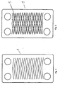
- Die Erfindung ist in den Zeichnungen schematisch und beispielhaft dargestellt und wird im Folgenden unter Bezugnahme auf die Zeichnungen näher erläutert. Hier zeigt
- Fig. 1
- die Draufsicht eines gewellten Bleches
- Fig. 2
- die Überlappung der Wellen beim Stapeln der Bleche und daraus resultierende Berührungspunkte
- Fig. 3
- einen Querschnitt durch 2 geschweißte, gewellte Bleche
- Fig. 4
- eine Prinzipskizze des Tampondrucks am Beispiel gewellter Bleche
- In dem erfindungsgemäßen Verfahren zur Herstellung eines beschichteten, strukturierten Wärmetauscherbleches 1 für einen Reaktor in einem Brennstoffzellensystem wird eine katalytische Komponente in mindestens einer Schicht in kontinuierlicher oder diskontinuierlicher Weise mittels Tampondruck ausschließlich in die Vertiefungen 2 und/oder Flanken 3 des Wärmetauscherbleches 1 aufgebracht. Die Oberfläche der erhabenen Teile 4 des Wärmetauscherblechs werden somit von der Beschichtung ausgespart. Beim Fügen der einzelnen Wärmetauscherbleche zu Reaktoren, die nur umfangsgeschweißt sind, sind somit die Berührungsflächen 5 bzw. Berührungspunkte nicht mit der katalytischen Komponente bedeckt. Aufgrund dieser gezielten Beschichtung wird die Katalysatorablösung bzw. das Abplatzen des Katalysators, welches zum Katalysatoraustrag infolge mechanischem und/oder thermischem Stress führt, minimiert.
- Die Beschichtung dieser strukturierten Bleche wird mittels Tampondruck vorgenommen. Beim Tampondruck handelt es sich um ein indirektes Druckverfahren, d.h. eine Platte, die Klischee genannt wird, dient als Vorlage, auf der das Druckbild als Vertiefung vorhanden ist. Das Klischee wird mittels eines Rakels mit einer sogenannten Druckpaste oder Druckflüssigkeit überschwemmt, die dann mit einem Messer wieder abgezogen wird. In den Vertiefungen des Klischees bleibt die Druckpaste oder Druckflüssigkeit hängen. Ein glatter, elastischer Stempel, genannt Tampon 6, bevorzugt aus Silikonkautschuk hergestellt, nimmt durch Aufdrücken einen Teil dieser Beschichtungsmasse aus den Vertiefungen auf und überträgt diese Masse auf den zu beschichtenden Gegenstand 1. Durch die Elastizität des Silikonkautschuks kann sich der Tampon 6, wie in Fig. 3 dargestellt, bei der Abgabe der Druckpaste oder Druckflüssigkeit dem zu bedruckenden Gegenstand anpassen. Dadurch wird das Bedrucken von nicht ebenen, strukturierten Blechen möglich, bei denen in vorteilhafter Weise nur die Vertiefungen 2 und/oder Flanken 3, nicht aber die erhabenen Flächen 4 des strukturierten Blechs 1 bedruckt werden sollen.
- Die Beschichtung des Wärmetauscherblechs mit der katalytischen Komponente kann durch einen oder mehrere Aufdrucke im Gesamtumfang des Bleches erfolgen. Die Beschichtung kann aber auch durch zonenweises Beschichten der Wärmstauscherbleche erfolgen. Durch den Mehrfachdruck lassen sich die einzelnen Schichten funktionalisieren, so daß beispielsweise zum einen am Reaktoreingang ein anderer Katalysator wie am Reaktorausgang aufgebracht, zum anderen über die Blechlänge die Menge an Katalysator zum Aufbau eines Gradienten variiert werden kann. In beiden genannten Fällen dient diese Vorgehensweise zur selektiven Steuerung von Umsätzen und Reaktionen innerhalb des Reaktors. Würde man dieses Vorgehen mittels Sprühbeschichtung durchführen wollen, wären aufwendige Maskierungen der jeweiligen Zonen notwendig. Dies würde das Verfahren zusätzlich zum Oversprayeffekt unnötig verteuern und relativ aufwendig gestalten. Mittels Spül- oder Tauchbeschichtung läßt sich keine zonenweise Beschichtung realisieren, bestenfalls kann ein Gradient in Höhe der Beschichtung aufgebracht werden. Obengenanntes Verfahren kann sowohl in diskontinuierlicher als auch in kontinuierlicher Art und Weise erfolgen, wobei beim Druckvorgang das Blech bzw. Blechband kurz angehalten, bedruckt und anschließend sensorgesteuert um ein bestimmtes Rastermaß weiterbewegt wird. Die mittels Tampondruck aufgebrachten Schichtdicken bewegen sich im Bereich von etwa 5 bis 50 µm der Gesamtschichtdicke.
- Die durch Tampondruck aufzubringende katalytische Komponente enthält eine katalytisch aktive und/oder eine wasserabweisende Materialkomponente. Die Beschichtung mit den jeweiligen Materialkomponenten kann in gemischter Form oder als Einzelschicht erfolgen, d.h. auf das Blech wird zunächst eine die katalytisch wirksame Unterschicht und darauf eine die wasserabweisende Materialkomponente enthaltende Oberschicht aufgedruckt. Da der Tampondruck nicht flächenförmig, sondern in Form von Mustern aufgebracht werden kann, wird beim zuerst erfolgten Auftrag der katalytisch aktiven Materialkomponente diese durch den nachfolgenden Aufdruck der wasserabweisenden Materialkomponente nicht vollflächig abgedeckt, so daß die Reaktionsgase und/oder Dämpfe den Katalysator noch erreichen können und damit die katalytische Aktivität erhalten bleibt, aber ein "Überfluten des Katalysators", d.h. eine vollständige Belegung des Katalysators mit Tröpfchen und/oder einem Flüssigkeitsfilm durch Kondensation von Wasserdampf und die damit einhergehende Aktivitätsverminderung oder Desaktivierung des Katalysators, vermieden wird. Zum einen gewährleistet somit der Verbund der katalytisch wirksamen mit der wasserabweisenden Materialkomponente, daß der Katalysator nicht durch Kondensatbildung an kalten Stellen im Brennstoffzellensystem in seiner Reaktivität gehindert ist, sondern vor allem beim Kaltstart weitestgehend zur Verfügung steht, zum anderen verhindert dieser Verbund durch Verkleben und/oder Vernetzen vorteilhafterweise ein Abplatzen oder den Austrag des Katalysators oder vermindert diese Effekte weitestgehend.
- Wie bereits in der Patentanmeldung EP 1243334 der Anmelderin beschrieben, werden als katalytisch aktives Material bevorzugt Metalle aus den Nebengruppen des Periodensystems Ib, IIb, VIIb und/oder VIIIb ausgewählt, wobei zusätzlich auch Substanzen enthalten sein können, denen Elemente aus anderen Gruppen des Periodensystems zugrunde liegen, wie beispielsweise Oxide der seltenen Erden zur thermischen Stabilisierung des Katalysators. Die mindestens eine Katalysatormaterialkomponente und/oder katalysatorhaltige Materialkomponente liegt bevorzugt geträgert vor. Entsprechend dem Stand der Technik gibt es eine Reihe von Trägermaterialien für Katalysatoren wie beispielsweise Keramik, Kohlenstoff, Kunststoff, Metall etc. Es eignen sich besonders poröse Feststoffe, auf dessen Oberfläche katalytisch wirksames Material abgeschieden wird. Besonders bevorzugt werden als Trägermaterialien keramische Werkstoffe wie z.B. Zeolithe, Al2O3, SiO2, ZrO2, CeO2 und/oder Mischungen davon eingesetzt.
- Das mindestens eine wasserabweisende Material enthält bevorzugt Silicone oder siliconhaltige Materialien, fluorierte Polymere wie z.B. Polytetrafluorethylen oder polytetrafluorethylenhaltige Materialien, Epoxidharz oder epoxidharzhaltige Materialien, Phenolharz oder phenolharzhaltige Materialien, Acrylharz oder acrylharzhaltige Materialien, PUR-Klebstoffmaterialien oder PUR-klebstoffhaltige Materialien oder Kunstharz/Schellackgemische oder kunstharzhaltige/schellackhaltige Gemische. Im Bereich der fluorierten Polymere eignet sich besonders Polytetrafluorethylen (PTFE) als wasserabweisende Komponente und Bindemittel für Katalysatoren. Im Bereich der Silicone finden besonders bevorzugt Siliconharze Anwendung, die eine hohe Dauerwärmebeständigkeit im Einsatzbereich aufweisen müssen. Diese Einsatztemperaturen liegen im Bereich zwischen etwa 30°C bis 650°C, bevorzugt im Bereich zwischen etwa 50°C bis 300°C. Als ein weiterer Vorteil zeigt sich, daß bei der Verwendung von Edelmetall als katalytisch aktive Materialkomponente in Verbindung mit Siliconen als wasserabweisende Materialkomponente keine Vergiftungserscheinungen durch Katalysatorgifte auftreten, wie dies z.B. bei der Verwendung von Kupfer als katalytische Komponente der Fall ist.
- Es ist außerdem äußerst vorteilhaft, wenn die Schicht, die die wasserabweisende Materialkomponente enthält, eine durch den chemischen Stoff selbst bedingte Elastizität aufweist, die ein Abplatzen oder den Austrag von Katalysator aus der Schicht zusätzlich verhindert oder diese Effekte weitgehend vermindert. Durch die Vernetzung der wasserabweisenden Materialkomponente wirkt diese ferner als ein Bindemittel für den Katalysator. Der Anteil an wasserabweisender Materialkomponente in Bezug auf die katalytisch wirksame Materialkomponente und/oder katalysatorhaltige Materialkomponente beträgt 1 bis 50 Gewichtsprozent, bevorzugt 5 bis 25 Gewichtsprozent.
- Die zum Druck benötigte Katalysatorpaste oder -suspension oder -flüssigkeit kann neben mindestens einer katalytisch aktiven Materialkomponente bevorzugt einen keramischen Binder enthalten, der nach Calcinierung an Luft bei etwa 500°C auch vernetzt werden kann, und Wasser. Als keramische Binder eignen sich besonders Oxide und/oder Hydroxide von Al, Ce, Si, Zr und/oder Mischungen davon, wobei vorzugsweise solche Einsatz finden, die vernetzt werden können.
- Enthält die zum Druck benötigte Katalysatorpaste oder -suspension oder -flüssigkeit ein polymeres Bindemittel, das bei den für das Calcinieren notwendigen Temperaturen abbaut, entfällt der Calcinierungsschritt und es folgen nur ein oder mehrere Trocknungsschritte. Eine Ausnahme hiervon stellt die Verwendung von PTFE als polymeres Bindemittel dar, da dieses Material kurzzeitig höhere Temperaturen aushält.
- Weitere Zusätze, wie beispielsweise zur Steuerung der Viskosität, des Benetzungsverhaltens auf dem Stempel oder zur pH-Einstellung, können in der Druckpaste, -suspension oder -flüssigkeit ebenfalls vorhanden sein. Um ein optimales Druckbild zu erreichen, muß die Form des Stempels der zu bedruckenden Fläche angepaßt sein. Die Anpassung der Verfahrensparameter an den Druckvorgang sind material-, temperatur- und verfahrensschrittabhängig und können mittels üblichem drucktechnischen Können gelöst werden.
- Der Druckvorgang selbst wird bei Raumtemperatur durchgeführt, wobei das Druckmedium (der Stempel oder Tampon) und die Beschichtungsmasse (Druckpaste, -suspension oder -flüssigkeit) nicht erwärmt werden.
- Das Wärmetauscherblech kann während des Aufbringens der katalytischen Komponente auf bis zu 200°C aufgeheizt werden. Dies bedingt vorteilhafterweise ein schnelleres Abtrocknen der Beschichtungsmasse, vor allem bei Mehrfachdruck.
- Sofern beim Aufbringen der Druckpaste, -suspension oder -flüssigkeit auf das Wärmstauscherblech dieses nicht beheizt wird, ist dem Druckschritt ein Trocknungsschritt in einem Temperaturbereich von etwa 100 bis 200°C zur besseren Haftung der Beschichtung nachgeschaltet. Zur Trocknung können Umluft/Durchlauftrockner, aber auch Strahlungstrockner, z.B. mittels Infrarot, eingesetzt werden. Die benötigte Trocknungszeit wird über die Durchlaufgeschwindigkeit des Bleches oder Blechbandes geregelt. An den Trocknungsschritt können sich weitere Druckvorgänge anschließen.
- Anschließend wird der das Verfahren abschließende Calcinierungsschritt bei etwa 500°C durchgeführt, der zur endgültigen Trocknung und zur Vernetzung des in der Beschichtung enthaltenen keramischen Binders beiträgt. Die Dauer des Calcinierungsschrittes bewegt sich zwischen 0,5 bis 4 Stunden.
- Wird als wasserabweisende Materialkomponente beispielsweise Silikon oder silikonhaltiges Material, das bei den für das Calcinieren notwendigen Temperaturen abbaut, verwendet, muß der Calcinierungsschritt vor dem Auftrag des Silikon oder silikonhaitigen Materials erfolgen. Zur Trocknung der nachfolgend aufgebrachten Silikon- oder silikonhaltigen Schicht wird bzw. werden noch ein oder mehrere Trocknungsschritte nachgeschaltet.
- Die nach dem erfindungsgemäßen Verfahren hergestellten Wärmetauscherbleche eignen sich gleichermaßen für den Einsatz als Reaktor in Wasserstoff-, Reformat- und Direkt-Methanolbetriebenen Brennstoffzellensystemen.
Claims (10)
- Verfahren zur Herstellung eines beschichteten, strukturierten Wärmetauscherbleches für einen Reaktor in einem Brennstoffzellensytem, wobei eine katalytische Komponente in mindestens einer Schicht in kontinuierlicher oder diskontinuierlicher Weise mittels Tampondruck ausschließlich in die Vertiefungen und/oder Flanken des Wärmetauscherbleches aufgebracht wird.
- Verfahren nach Anspruch 1,
dadurch gekennzeichnet,
daß die katalytische Komponente zonenweise aufgebracht wird. - Verfahren nach Anspruch 1,
dadurch gekennzeichnet,
daß die katalytische Komponente eine katalytisch aktive Materialkomponente und/oder eine wasserabweisende Materialkomponente enthält. - Verfahren nach Anspruch 3,
dadurch gekennzeichnet,
daß die katalytisch wirksame Materialkomponente bevorzugt geträgert vorliegt. - Verfahren nach Anspruch 3,
dadurch gekennzeichnet,
daß die katalytisch wirksame Materialkomponente ein keramisches und/oder ein polymeres Bindemittel enthält. - Verfahren nach Anspruch 3, wobei die Zusammensetzung und/oder Konzentration der katalytisch aktiven Materialkomponente über die Länge des Wärmetauscherbleches variiert ist.
- Verfahren nach Anspruch 1,
dadurch gekennzeichnet,
daß der Druckvorgang bei Raumtemperatur durchgeführt wird, wobei Druckmedium und Beschichtungsmasse nicht erwärmt werden. - Verfahren nach Anspruch 7,
dadurch gekennzeichnet,
daß nach dem Druckschritt ein Trocknungsschritt in einem Temperaturbereich von etwa 100 bis 200°C durchgeführt wird. - Verfahren nach Anspruch 7,
dadurch gekennzeichnet,
daß das Wärmetauscherblech während des Aufbringens der katalytischen Komponente beheizt wird. - Verfahren nach Anspruch 8 oder 9,
dadurch gekennzeichnet,
daß der das Verfahren abschließende Calcinierungsschritt bei einer Temperatur von etwa 500°C durchgeführt wird.
Applications Claiming Priority (2)
| Application Number | Priority Date | Filing Date | Title |
|---|---|---|---|
| DE10129099 | 2001-06-16 | ||
| DE10129099A DE10129099A1 (de) | 2001-06-16 | 2001-06-16 | Katalytische Beschichtung von strukturierten Wärmetauscherblechen |
Publications (3)
| Publication Number | Publication Date |
|---|---|
| EP1266701A2 EP1266701A2 (de) | 2002-12-18 |
| EP1266701A3 EP1266701A3 (de) | 2005-11-02 |
| EP1266701B1 true EP1266701B1 (de) | 2006-08-23 |
Family
ID=7688425
Family Applications (1)
| Application Number | Title | Priority Date | Filing Date |
|---|---|---|---|
| EP02011805A Expired - Lifetime EP1266701B1 (de) | 2001-06-16 | 2002-05-28 | Katalytische Beschichtung von strukturierten Wärmetauschern |
Country Status (3)
| Country | Link |
|---|---|
| US (1) | US20030014865A1 (de) |
| EP (1) | EP1266701B1 (de) |
| DE (2) | DE10129099A1 (de) |
Families Citing this family (8)
| Publication number | Priority date | Publication date | Assignee | Title |
|---|---|---|---|---|
| US7250141B2 (en) * | 2004-02-27 | 2007-07-31 | Honeywell International, Inc. | Augmented catalytic heat exchanger system |
| US7618598B2 (en) | 2004-11-29 | 2009-11-17 | Modine Manufacturing Company | Catalytic reactor/heat exchanger |
| GB0608927D0 (en) * | 2006-05-08 | 2006-06-14 | Accentus Plc | Catalytic Reactor |
| EP2384812A3 (de) * | 2006-05-08 | 2011-12-21 | CompactGTL plc | Schnelle Reaktionen in einem kompakten katalytischen Reaktors |
| DE102007042193A1 (de) * | 2007-08-29 | 2009-03-05 | Deutsches Zentrum für Luft- und Raumfahrt e.V. | Verfahren zur Herstellung einer Beschichtung auf einem Träger und Presswerkzeug oder Gegenwerkzeug |
| FR3053607B1 (fr) * | 2016-07-05 | 2020-01-10 | L'air Liquide, Societe Anonyme Pour L'etude Et L'exploitation Des Procedes Georges Claude | Procede de formulation d'une suspension catalytique |
| US11660819B2 (en) | 2016-11-02 | 2023-05-30 | R3 Printing, Inc. | System and method for automated successive three-dimensional printing |
| US10710302B2 (en) | 2016-11-02 | 2020-07-14 | R3 Printing, Inc. | System and method for automated successive three-dimensional printing |
Family Cites Families (11)
| Publication number | Priority date | Publication date | Assignee | Title |
|---|---|---|---|---|
| US4567117A (en) * | 1982-07-08 | 1986-01-28 | Energy Research Corporation | Fuel cell employing non-uniform catalyst |
| DE3225764A1 (de) * | 1982-07-09 | 1984-01-12 | Arnold Dipl.-Ing. 3004 Isernhagen Vogts | Mehrschaliger leichtbaukoerper, insbesondere flaechenwaermetauscher sowie verfahren und spritzkopf zu seiner herstellung aus kunststoff |
| US5181558A (en) * | 1990-11-13 | 1993-01-26 | Matsushita Refrigeration Company | Heat exchanger |
| DE4104960A1 (de) * | 1991-02-18 | 1992-04-02 | Siemens Ag | Waermetauscher |
| DE4104959A1 (de) * | 1991-02-18 | 1992-08-20 | Siemens Ag | Waermetauscher |
| DE19511817C2 (de) * | 1995-03-30 | 1997-10-09 | Aeg Energietechnik Gmbh | Wärmetauscher in Plattenbauweise mit Reformer |
| US5837609A (en) * | 1997-01-16 | 1998-11-17 | Ford Motor Company | Fully additive method of applying a circuit pattern to a three-dimensional, nonconductive part |
| DE19825102C2 (de) * | 1998-06-05 | 2001-09-27 | Xcellsis Gmbh | Verfahren zur Herstellung eines kompakten katalytischen Reaktors |
| US6197365B1 (en) * | 1999-03-30 | 2001-03-06 | Xcellsis Gmbh | Process for manufacturing a catalytic material |
| DE19947803A1 (de) * | 1999-10-05 | 2001-04-12 | Behr Gmbh & Co | Reaktor mit Wärmeübertragerstruktur |
| DE10114646A1 (de) * | 2001-03-24 | 2002-09-26 | Xcellsis Gmbh | Herstellung einer festhaftenden, wasserabweisenden Katalysatorschicht |
-
2001
- 2001-06-16 DE DE10129099A patent/DE10129099A1/de not_active Withdrawn
-
2002
- 2002-05-28 DE DE50207903T patent/DE50207903D1/de not_active Expired - Fee Related
- 2002-05-28 EP EP02011805A patent/EP1266701B1/de not_active Expired - Lifetime
- 2002-06-14 US US10/171,512 patent/US20030014865A1/en not_active Abandoned
Also Published As
| Publication number | Publication date |
|---|---|
| EP1266701A2 (de) | 2002-12-18 |
| DE10129099A1 (de) | 2002-12-19 |
| EP1266701A3 (de) | 2005-11-02 |
| US20030014865A1 (en) | 2003-01-23 |
| DE50207903D1 (de) | 2006-10-05 |
Similar Documents
| Publication | Publication Date | Title |
|---|---|---|
| DE69916858T2 (de) | Katalytischer konverter zum entfernen von ozon mit anodisierter schicht und überzug | |
| DE2104019C3 (de) | Katalysator zur Anreicherung von flüssigem Wasser mit Wasserstoffisotopen aus Wasserstoffgas | |
| EP1476313B1 (de) | Verfahren und einrichtung zum drucken, wobei vor dem auftrag der farbabstossenden oder farbanziehenden schicht eine benetzungsfördernde substanz aufgetragen wird | |
| EP2131949B1 (de) | Verfahren zur einbringung einer katalytischen beschichtung in die poren eines keramischen durchfluss-wabenkörpers | |
| DE3041961A1 (de) | Mit oxidwhiskern bedeckte folie und verfahren zu ihrer herstellung | |
| DE60005925T2 (de) | Verfahren zur selektiven hydrierung, sowie katalysator zur verwendung dabei | |
| DE68927770T2 (de) | Katalytischer Verbundstoff auf der Basis von Delafosite zur Reinigung von Abgasen und Verfahren zu seiner Herstellung | |
| DE2816471A1 (de) | Verfahren zum herstellen von formaldehyden und katalysator fuer dieses verfahren | |
| DE2804660A1 (de) | Katalysator | |
| DE69030251T2 (de) | Thermisches verfahren zur herstellung von papierschablone | |
| DE69609372T2 (de) | Musterbildende Schicht und daraus hergestelltes Etikett | |
| EP1043068A2 (de) | Verfahren zur Herstellung eines Katalysators | |
| DE60307277T2 (de) | Anodengestützte brennstoffzelle | |
| EP1266701A2 (de) | Katalytische Beschichtung von strukturierten Wärmetauschern | |
| DE102018212110B4 (de) | Verfahren zur Herstellung eines offenporigen Metallkörpers mit einer Oxidschicht und ein mit dem Verfahren hergestellter Metallkörper | |
| EP1243334A1 (de) | Herstellung einer wasserabweisenden Katalysatorschicht auf einem keramischen oder metallischen Träger | |
| EP1346424B1 (de) | Verfahren zur herstellung von elektroden, komponenten, halbzellen und zellen für elektrochmische energiewandler | |
| DE69411464T2 (de) | Plattenherstellungsverfahren für eine Schablone | |
| EP1385702B1 (de) | Aufzug für einen bogenführungszylinder in einer druckmaschine | |
| EP0564830A2 (de) | Monolithischer Trägerkatalysator, Verfahren zu seiner Herstellung und seine Verwendung | |
| DE102018128079A1 (de) | Verfahren zur Herstellung eines Separators für eine Brennstoffzelle | |
| DE68909306T2 (de) | Verfahren zur Herstellung einer Brennstoffzellen-Matrix. | |
| DE19963443A1 (de) | Dünnschichtkatalysatoren auf Basis von Raney-Legierungen und Verfahren zu deren Herstellung | |
| DE60225983T2 (de) | Verfahren zum Beschichten einer Düsenplatte | |
| EP1034843A1 (de) | Verfahren zur Herstellung einer beschichteten Struktur, die sich zum Durchführen von heterogenen Katalysen eignet |
Legal Events
| Date | Code | Title | Description |
|---|---|---|---|
| PUAI | Public reference made under article 153(3) epc to a published international application that has entered the european phase |
Free format text: ORIGINAL CODE: 0009012 |
|
| AK | Designated contracting states |
Kind code of ref document: A2 Designated state(s): AT BE CH CY DE DK ES FI FR GB GR IE IT LI LU MC NL PT SE TR |
|
| AX | Request for extension of the european patent |
Free format text: AL;LT;LV;MK;RO;SI |
|
| PUAL | Search report despatched |
Free format text: ORIGINAL CODE: 0009013 |
|
| AK | Designated contracting states |
Kind code of ref document: A3 Designated state(s): AT BE CH CY DE DK ES FI FR GB GR IE IT LI LU MC NL PT SE TR |
|
| AX | Request for extension of the european patent |
Extension state: AL LT LV MK RO SI |
|
| RIC1 | Information provided on ipc code assigned before grant |
Ipc: 7H 01M 8/04 B Ipc: 7F 28F 3/04 B Ipc: 7H 01M 8/06 B Ipc: 7H 01M 8/02 B Ipc: 7B 01J 35/04 B Ipc: 7F 28D 9/00 B Ipc: 7B 01J 19/24 B Ipc: 7B 05D 1/28 A |
|
| RAP1 | Party data changed (applicant data changed or rights of an application transferred) |
Owner name: NUCELLSYS GMBH |
|
| GRAP | Despatch of communication of intention to grant a patent |
Free format text: ORIGINAL CODE: EPIDOSNIGR1 |
|
| 17P | Request for examination filed |
Effective date: 20051223 |
|
| AKX | Designation fees paid |
Designated state(s): DE FR GB IT |
|
| GRAS | Grant fee paid |
Free format text: ORIGINAL CODE: EPIDOSNIGR3 |
|
| GRAA | (expected) grant |
Free format text: ORIGINAL CODE: 0009210 |
|
| AK | Designated contracting states |
Kind code of ref document: B1 Designated state(s): DE FR GB IT |
|
| PG25 | Lapsed in a contracting state [announced via postgrant information from national office to epo] |
Ref country code: IT Free format text: LAPSE BECAUSE OF FAILURE TO SUBMIT A TRANSLATION OF THE DESCRIPTION OR TO PAY THE FEE WITHIN THE PRESCRIBED TIME-LIMIT;WARNING: LAPSES OF ITALIAN PATENTS WITH EFFECTIVE DATE BEFORE 2007 MAY HAVE OCCURRED AT ANY TIME BEFORE 2007. THE CORRECT EFFECTIVE DATE MAY BE DIFFERENT FROM THE ONE RECORDED. Effective date: 20060823 |
|
| REG | Reference to a national code |
Ref country code: GB Ref legal event code: FG4D Free format text: NOT ENGLISH |
|
| REF | Corresponds to: |
Ref document number: 50207903 Country of ref document: DE Date of ref document: 20061005 Kind code of ref document: P |
|
| GBT | Gb: translation of ep patent filed (gb section 77(6)(a)/1977) |
Effective date: 20061030 |
|
| ET | Fr: translation filed | ||
| PLBE | No opposition filed within time limit |
Free format text: ORIGINAL CODE: 0009261 |
|
| STAA | Information on the status of an ep patent application or granted ep patent |
Free format text: STATUS: NO OPPOSITION FILED WITHIN TIME LIMIT |
|
| 26N | No opposition filed |
Effective date: 20070524 |
|
| PGFP | Annual fee paid to national office [announced via postgrant information from national office to epo] |
Ref country code: DE Payment date: 20090525 Year of fee payment: 8 Ref country code: FR Payment date: 20090513 Year of fee payment: 8 Ref country code: IT Payment date: 20090523 Year of fee payment: 8 |
|
| PGFP | Annual fee paid to national office [announced via postgrant information from national office to epo] |
Ref country code: GB Payment date: 20090522 Year of fee payment: 8 |
|
| GBPC | Gb: european patent ceased through non-payment of renewal fee |
Effective date: 20100528 |
|
| REG | Reference to a national code |
Ref country code: FR Ref legal event code: ST Effective date: 20110131 |
|
| PG25 | Lapsed in a contracting state [announced via postgrant information from national office to epo] |
Ref country code: IT Free format text: LAPSE BECAUSE OF NON-PAYMENT OF DUE FEES Effective date: 20100528 |
|
| PG25 | Lapsed in a contracting state [announced via postgrant information from national office to epo] |
Ref country code: DE Free format text: LAPSE BECAUSE OF NON-PAYMENT OF DUE FEES Effective date: 20101201 |
|
| PG25 | Lapsed in a contracting state [announced via postgrant information from national office to epo] |
Ref country code: FR Free format text: LAPSE BECAUSE OF NON-PAYMENT OF DUE FEES Effective date: 20100531 |
|
| PG25 | Lapsed in a contracting state [announced via postgrant information from national office to epo] |
Ref country code: GB Free format text: LAPSE BECAUSE OF NON-PAYMENT OF DUE FEES Effective date: 20100528 |