EP1265236A2 - Method for manufacturing optical disc and method for transporting multi-layered optical disc - Google Patents
Method for manufacturing optical disc and method for transporting multi-layered optical disc Download PDFInfo
- Publication number
- EP1265236A2 EP1265236A2 EP02012390A EP02012390A EP1265236A2 EP 1265236 A2 EP1265236 A2 EP 1265236A2 EP 02012390 A EP02012390 A EP 02012390A EP 02012390 A EP02012390 A EP 02012390A EP 1265236 A2 EP1265236 A2 EP 1265236A2
- Authority
- EP
- European Patent Office
- Prior art keywords
- disc
- sheet
- disc substrate
- adhesive
- layered
- Prior art date
- Legal status (The legal status is an assumption and is not a legal conclusion. Google has not performed a legal analysis and makes no representation as to the accuracy of the status listed.)
- Withdrawn
Links
- 230000003287 optical effect Effects 0.000 title claims abstract description 87
- 238000000034 method Methods 0.000 title claims abstract description 55
- 238000004519 manufacturing process Methods 0.000 title claims abstract description 18
- 239000000758 substrate Substances 0.000 claims abstract description 219
- 239000000853 adhesive Substances 0.000 claims abstract description 177
- 230000001070 adhesive effect Effects 0.000 claims abstract description 177
- 238000005520 cutting process Methods 0.000 claims abstract description 28
- 230000008569 process Effects 0.000 claims description 13
- 230000032258 transport Effects 0.000 claims description 7
- 230000000149 penetrating effect Effects 0.000 claims description 3
- 206010040844 Skin exfoliation Diseases 0.000 description 12
- 238000004299 exfoliation Methods 0.000 description 12
- 238000003780 insertion Methods 0.000 description 9
- 230000037431 insertion Effects 0.000 description 9
- 239000011347 resin Substances 0.000 description 8
- 229920005989 resin Polymers 0.000 description 8
- 238000004528 spin coating Methods 0.000 description 8
- 230000037303 wrinkles Effects 0.000 description 8
- 238000000465 moulding Methods 0.000 description 7
- 239000010409 thin film Substances 0.000 description 7
- 230000005540 biological transmission Effects 0.000 description 6
- 239000000463 material Substances 0.000 description 6
- 210000000078 claw Anatomy 0.000 description 5
- 229920000515 polycarbonate Polymers 0.000 description 5
- 239000004417 polycarbonate Substances 0.000 description 5
- 239000005020 polyethylene terephthalate Substances 0.000 description 5
- 229920000139 polyethylene terephthalate Polymers 0.000 description 5
- 206010073261 Ovarian theca cell tumour Diseases 0.000 description 3
- 230000004075 alteration Effects 0.000 description 3
- 230000015556 catabolic process Effects 0.000 description 3
- 238000006243 chemical reaction Methods 0.000 description 3
- 238000006731 degradation reaction Methods 0.000 description 3
- 230000031700 light absorption Effects 0.000 description 3
- 230000007246 mechanism Effects 0.000 description 3
- 208000001644 thecoma Diseases 0.000 description 3
- 230000008901 benefit Effects 0.000 description 2
- 230000015572 biosynthetic process Effects 0.000 description 2
- 239000000428 dust Substances 0.000 description 2
- 239000010408 film Substances 0.000 description 2
- 239000007788 liquid Substances 0.000 description 2
- 238000012986 modification Methods 0.000 description 2
- 230000004048 modification Effects 0.000 description 2
- -1 polyethylene terephthalate Polymers 0.000 description 2
- 239000000047 product Substances 0.000 description 2
- 230000000630 rising effect Effects 0.000 description 2
- 238000003860 storage Methods 0.000 description 2
- BQCADISMDOOEFD-UHFFFAOYSA-N Silver Chemical compound [Ag] BQCADISMDOOEFD-UHFFFAOYSA-N 0.000 description 1
- 239000013065 commercial product Substances 0.000 description 1
- 238000009792 diffusion process Methods 0.000 description 1
- 238000006073 displacement reaction Methods 0.000 description 1
- 238000002844 melting Methods 0.000 description 1
- 230000008018 melting Effects 0.000 description 1
- 239000003973 paint Substances 0.000 description 1
- 230000002093 peripheral effect Effects 0.000 description 1
- 230000009467 reduction Effects 0.000 description 1
- 229910052709 silver Inorganic materials 0.000 description 1
- 239000004332 silver Substances 0.000 description 1
Images




Classifications
-
- B—PERFORMING OPERATIONS; TRANSPORTING
- B29—WORKING OF PLASTICS; WORKING OF SUBSTANCES IN A PLASTIC STATE IN GENERAL
- B29C—SHAPING OR JOINING OF PLASTICS; SHAPING OF MATERIAL IN A PLASTIC STATE, NOT OTHERWISE PROVIDED FOR; AFTER-TREATMENT OF THE SHAPED PRODUCTS, e.g. REPAIRING
- B29C65/00—Joining or sealing of preformed parts, e.g. welding of plastics materials; Apparatus therefor
- B29C65/48—Joining or sealing of preformed parts, e.g. welding of plastics materials; Apparatus therefor using adhesives, i.e. using supplementary joining material; solvent bonding
- B29C65/52—Joining or sealing of preformed parts, e.g. welding of plastics materials; Apparatus therefor using adhesives, i.e. using supplementary joining material; solvent bonding characterised by the way of applying the adhesive
- B29C65/521—Joining or sealing of preformed parts, e.g. welding of plastics materials; Apparatus therefor using adhesives, i.e. using supplementary joining material; solvent bonding characterised by the way of applying the adhesive by spin coating
-
- B—PERFORMING OPERATIONS; TRANSPORTING
- B29—WORKING OF PLASTICS; WORKING OF SUBSTANCES IN A PLASTIC STATE IN GENERAL
- B29C—SHAPING OR JOINING OF PLASTICS; SHAPING OF MATERIAL IN A PLASTIC STATE, NOT OTHERWISE PROVIDED FOR; AFTER-TREATMENT OF THE SHAPED PRODUCTS, e.g. REPAIRING
- B29C65/00—Joining or sealing of preformed parts, e.g. welding of plastics materials; Apparatus therefor
- B29C65/02—Joining or sealing of preformed parts, e.g. welding of plastics materials; Apparatus therefor by heating, with or without pressure
- B29C65/14—Joining or sealing of preformed parts, e.g. welding of plastics materials; Apparatus therefor by heating, with or without pressure using wave energy, i.e. electromagnetic radiation, or particle radiation
- B29C65/1403—Joining or sealing of preformed parts, e.g. welding of plastics materials; Apparatus therefor by heating, with or without pressure using wave energy, i.e. electromagnetic radiation, or particle radiation characterised by the type of electromagnetic or particle radiation
- B29C65/1406—Ultraviolet [UV] radiation
-
- B—PERFORMING OPERATIONS; TRANSPORTING
- B29—WORKING OF PLASTICS; WORKING OF SUBSTANCES IN A PLASTIC STATE IN GENERAL
- B29C—SHAPING OR JOINING OF PLASTICS; SHAPING OF MATERIAL IN A PLASTIC STATE, NOT OTHERWISE PROVIDED FOR; AFTER-TREATMENT OF THE SHAPED PRODUCTS, e.g. REPAIRING
- B29C65/00—Joining or sealing of preformed parts, e.g. welding of plastics materials; Apparatus therefor
- B29C65/02—Joining or sealing of preformed parts, e.g. welding of plastics materials; Apparatus therefor by heating, with or without pressure
- B29C65/14—Joining or sealing of preformed parts, e.g. welding of plastics materials; Apparatus therefor by heating, with or without pressure using wave energy, i.e. electromagnetic radiation, or particle radiation
- B29C65/1429—Joining or sealing of preformed parts, e.g. welding of plastics materials; Apparatus therefor by heating, with or without pressure using wave energy, i.e. electromagnetic radiation, or particle radiation characterised by the way of heating the interface
- B29C65/1435—Joining or sealing of preformed parts, e.g. welding of plastics materials; Apparatus therefor by heating, with or without pressure using wave energy, i.e. electromagnetic radiation, or particle radiation characterised by the way of heating the interface at least passing through one of the parts to be joined, i.e. transmission welding
-
- B—PERFORMING OPERATIONS; TRANSPORTING
- B29—WORKING OF PLASTICS; WORKING OF SUBSTANCES IN A PLASTIC STATE IN GENERAL
- B29C—SHAPING OR JOINING OF PLASTICS; SHAPING OF MATERIAL IN A PLASTIC STATE, NOT OTHERWISE PROVIDED FOR; AFTER-TREATMENT OF THE SHAPED PRODUCTS, e.g. REPAIRING
- B29C65/00—Joining or sealing of preformed parts, e.g. welding of plastics materials; Apparatus therefor
- B29C65/02—Joining or sealing of preformed parts, e.g. welding of plastics materials; Apparatus therefor by heating, with or without pressure
- B29C65/14—Joining or sealing of preformed parts, e.g. welding of plastics materials; Apparatus therefor by heating, with or without pressure using wave energy, i.e. electromagnetic radiation, or particle radiation
- B29C65/1429—Joining or sealing of preformed parts, e.g. welding of plastics materials; Apparatus therefor by heating, with or without pressure using wave energy, i.e. electromagnetic radiation, or particle radiation characterised by the way of heating the interface
- B29C65/1448—Joining or sealing of preformed parts, e.g. welding of plastics materials; Apparatus therefor by heating, with or without pressure using wave energy, i.e. electromagnetic radiation, or particle radiation characterised by the way of heating the interface radiating the edges of the parts to be joined, e.g. for curing a layer of adhesive placed between two flat parts to be joined, e.g. for making CDs or DVDs
-
- B—PERFORMING OPERATIONS; TRANSPORTING
- B29—WORKING OF PLASTICS; WORKING OF SUBSTANCES IN A PLASTIC STATE IN GENERAL
- B29C—SHAPING OR JOINING OF PLASTICS; SHAPING OF MATERIAL IN A PLASTIC STATE, NOT OTHERWISE PROVIDED FOR; AFTER-TREATMENT OF THE SHAPED PRODUCTS, e.g. REPAIRING
- B29C65/00—Joining or sealing of preformed parts, e.g. welding of plastics materials; Apparatus therefor
- B29C65/02—Joining or sealing of preformed parts, e.g. welding of plastics materials; Apparatus therefor by heating, with or without pressure
- B29C65/14—Joining or sealing of preformed parts, e.g. welding of plastics materials; Apparatus therefor by heating, with or without pressure using wave energy, i.e. electromagnetic radiation, or particle radiation
- B29C65/1477—Joining or sealing of preformed parts, e.g. welding of plastics materials; Apparatus therefor by heating, with or without pressure using wave energy, i.e. electromagnetic radiation, or particle radiation making use of an absorber or impact modifier
- B29C65/1483—Joining or sealing of preformed parts, e.g. welding of plastics materials; Apparatus therefor by heating, with or without pressure using wave energy, i.e. electromagnetic radiation, or particle radiation making use of an absorber or impact modifier coated on the article
-
- B—PERFORMING OPERATIONS; TRANSPORTING
- B29—WORKING OF PLASTICS; WORKING OF SUBSTANCES IN A PLASTIC STATE IN GENERAL
- B29C—SHAPING OR JOINING OF PLASTICS; SHAPING OF MATERIAL IN A PLASTIC STATE, NOT OTHERWISE PROVIDED FOR; AFTER-TREATMENT OF THE SHAPED PRODUCTS, e.g. REPAIRING
- B29C65/00—Joining or sealing of preformed parts, e.g. welding of plastics materials; Apparatus therefor
- B29C65/48—Joining or sealing of preformed parts, e.g. welding of plastics materials; Apparatus therefor using adhesives, i.e. using supplementary joining material; solvent bonding
- B29C65/4805—Joining or sealing of preformed parts, e.g. welding of plastics materials; Apparatus therefor using adhesives, i.e. using supplementary joining material; solvent bonding characterised by the type of adhesives
- B29C65/483—Reactive adhesives, e.g. chemically curing adhesives
- B29C65/4845—Radiation curing adhesives, e.g. UV light curing adhesives
-
- B—PERFORMING OPERATIONS; TRANSPORTING
- B29—WORKING OF PLASTICS; WORKING OF SUBSTANCES IN A PLASTIC STATE IN GENERAL
- B29C—SHAPING OR JOINING OF PLASTICS; SHAPING OF MATERIAL IN A PLASTIC STATE, NOT OTHERWISE PROVIDED FOR; AFTER-TREATMENT OF THE SHAPED PRODUCTS, e.g. REPAIRING
- B29C65/00—Joining or sealing of preformed parts, e.g. welding of plastics materials; Apparatus therefor
- B29C65/78—Means for handling the parts to be joined, e.g. for making containers or hollow articles, e.g. means for handling sheets, plates, web-like materials, tubular articles, hollow articles or elements to be joined therewith; Means for discharging the joined articles from the joining apparatus
- B29C65/7802—Positioning the parts to be joined, e.g. aligning, indexing or centring
- B29C65/7805—Positioning the parts to be joined, e.g. aligning, indexing or centring the parts to be joined comprising positioning features
- B29C65/7808—Positioning the parts to be joined, e.g. aligning, indexing or centring the parts to be joined comprising positioning features in the form of holes or slots
- B29C65/7811—Positioning the parts to be joined, e.g. aligning, indexing or centring the parts to be joined comprising positioning features in the form of holes or slots for centring purposes
-
- B—PERFORMING OPERATIONS; TRANSPORTING
- B29—WORKING OF PLASTICS; WORKING OF SUBSTANCES IN A PLASTIC STATE IN GENERAL
- B29C—SHAPING OR JOINING OF PLASTICS; SHAPING OF MATERIAL IN A PLASTIC STATE, NOT OTHERWISE PROVIDED FOR; AFTER-TREATMENT OF THE SHAPED PRODUCTS, e.g. REPAIRING
- B29C65/00—Joining or sealing of preformed parts, e.g. welding of plastics materials; Apparatus therefor
- B29C65/78—Means for handling the parts to be joined, e.g. for making containers or hollow articles, e.g. means for handling sheets, plates, web-like materials, tubular articles, hollow articles or elements to be joined therewith; Means for discharging the joined articles from the joining apparatus
- B29C65/7841—Holding or clamping means for handling purposes
- B29C65/7847—Holding or clamping means for handling purposes using vacuum to hold at least one of the parts to be joined
-
- B—PERFORMING OPERATIONS; TRANSPORTING
- B29—WORKING OF PLASTICS; WORKING OF SUBSTANCES IN A PLASTIC STATE IN GENERAL
- B29C—SHAPING OR JOINING OF PLASTICS; SHAPING OF MATERIAL IN A PLASTIC STATE, NOT OTHERWISE PROVIDED FOR; AFTER-TREATMENT OF THE SHAPED PRODUCTS, e.g. REPAIRING
- B29C66/00—General aspects of processes or apparatus for joining preformed parts
- B29C66/01—General aspects dealing with the joint area or with the area to be joined
- B29C66/05—Particular design of joint configurations
- B29C66/10—Particular design of joint configurations particular design of the joint cross-sections
- B29C66/11—Joint cross-sections comprising a single joint-segment, i.e. one of the parts to be joined comprising a single joint-segment in the joint cross-section
- B29C66/112—Single lapped joints
- B29C66/1122—Single lap to lap joints, i.e. overlap joints
-
- B—PERFORMING OPERATIONS; TRANSPORTING
- B29—WORKING OF PLASTICS; WORKING OF SUBSTANCES IN A PLASTIC STATE IN GENERAL
- B29C—SHAPING OR JOINING OF PLASTICS; SHAPING OF MATERIAL IN A PLASTIC STATE, NOT OTHERWISE PROVIDED FOR; AFTER-TREATMENT OF THE SHAPED PRODUCTS, e.g. REPAIRING
- B29C66/00—General aspects of processes or apparatus for joining preformed parts
- B29C66/40—General aspects of joining substantially flat articles, e.g. plates, sheets or web-like materials; Making flat seams in tubular or hollow articles; Joining single elements to substantially flat surfaces
- B29C66/41—Joining substantially flat articles ; Making flat seams in tubular or hollow articles
- B29C66/45—Joining of substantially the whole surface of the articles
- B29C66/452—Joining of substantially the whole surface of the articles the article having a disc form, e.g. making CDs or DVDs
-
- B—PERFORMING OPERATIONS; TRANSPORTING
- B32—LAYERED PRODUCTS
- B32B—LAYERED PRODUCTS, i.e. PRODUCTS BUILT-UP OF STRATA OF FLAT OR NON-FLAT, e.g. CELLULAR OR HONEYCOMB, FORM
- B32B37/00—Methods or apparatus for laminating, e.g. by curing or by ultrasonic bonding
- B32B37/12—Methods or apparatus for laminating, e.g. by curing or by ultrasonic bonding characterised by using adhesives
- B32B37/1284—Application of adhesive
-
- G—PHYSICS
- G11—INFORMATION STORAGE
- G11B—INFORMATION STORAGE BASED ON RELATIVE MOVEMENT BETWEEN RECORD CARRIER AND TRANSDUCER
- G11B7/00—Recording or reproducing by optical means, e.g. recording using a thermal beam of optical radiation by modifying optical properties or the physical structure, reproducing using an optical beam at lower power by sensing optical properties; Record carriers therefor
- G11B7/24—Record carriers characterised by shape, structure or physical properties, or by the selection of the material
- G11B7/26—Apparatus or processes specially adapted for the manufacture of record carriers
- G11B7/265—Apparatus for the mass production of optical record carriers, e.g. complete production stations, transport systems
-
- B—PERFORMING OPERATIONS; TRANSPORTING
- B29—WORKING OF PLASTICS; WORKING OF SUBSTANCES IN A PLASTIC STATE IN GENERAL
- B29C—SHAPING OR JOINING OF PLASTICS; SHAPING OF MATERIAL IN A PLASTIC STATE, NOT OTHERWISE PROVIDED FOR; AFTER-TREATMENT OF THE SHAPED PRODUCTS, e.g. REPAIRING
- B29C35/00—Heating, cooling or curing, e.g. crosslinking or vulcanising; Apparatus therefor
- B29C35/02—Heating or curing, e.g. crosslinking or vulcanizing during moulding, e.g. in a mould
- B29C35/08—Heating or curing, e.g. crosslinking or vulcanizing during moulding, e.g. in a mould by wave energy or particle radiation
- B29C35/0805—Heating or curing, e.g. crosslinking or vulcanizing during moulding, e.g. in a mould by wave energy or particle radiation using electromagnetic radiation
- B29C2035/0827—Heating or curing, e.g. crosslinking or vulcanizing during moulding, e.g. in a mould by wave energy or particle radiation using electromagnetic radiation using UV radiation
-
- B—PERFORMING OPERATIONS; TRANSPORTING
- B29—WORKING OF PLASTICS; WORKING OF SUBSTANCES IN A PLASTIC STATE IN GENERAL
- B29C—SHAPING OR JOINING OF PLASTICS; SHAPING OF MATERIAL IN A PLASTIC STATE, NOT OTHERWISE PROVIDED FOR; AFTER-TREATMENT OF THE SHAPED PRODUCTS, e.g. REPAIRING
- B29C66/00—General aspects of processes or apparatus for joining preformed parts
- B29C66/70—General aspects of processes or apparatus for joining preformed parts characterised by the composition, physical properties or the structure of the material of the parts to be joined; Joining with non-plastics material
- B29C66/71—General aspects of processes or apparatus for joining preformed parts characterised by the composition, physical properties or the structure of the material of the parts to be joined; Joining with non-plastics material characterised by the composition of the plastics material of the parts to be joined
-
- B—PERFORMING OPERATIONS; TRANSPORTING
- B29—WORKING OF PLASTICS; WORKING OF SUBSTANCES IN A PLASTIC STATE IN GENERAL
- B29L—INDEXING SCHEME ASSOCIATED WITH SUBCLASS B29C, RELATING TO PARTICULAR ARTICLES
- B29L2017/00—Carriers for sound or information
- B29L2017/001—Carriers of records containing fine grooves or impressions, e.g. disc records for needle playback, cylinder records
- B29L2017/003—Records or discs
- B29L2017/005—CD''s, DVD''s
-
- B—PERFORMING OPERATIONS; TRANSPORTING
- B32—LAYERED PRODUCTS
- B32B—LAYERED PRODUCTS, i.e. PRODUCTS BUILT-UP OF STRATA OF FLAT OR NON-FLAT, e.g. CELLULAR OR HONEYCOMB, FORM
- B32B2429/00—Carriers for sound or information
- B32B2429/02—Records or discs
-
- G—PHYSICS
- G11—INFORMATION STORAGE
- G11B—INFORMATION STORAGE BASED ON RELATIVE MOVEMENT BETWEEN RECORD CARRIER AND TRANSDUCER
- G11B7/00—Recording or reproducing by optical means, e.g. recording using a thermal beam of optical radiation by modifying optical properties or the physical structure, reproducing using an optical beam at lower power by sensing optical properties; Record carriers therefor
- G11B7/24—Record carriers characterised by shape, structure or physical properties, or by the selection of the material
- G11B7/26—Apparatus or processes specially adapted for the manufacture of record carriers
- G11B7/266—Sputtering or spin-coating layers
-
- Y—GENERAL TAGGING OF NEW TECHNOLOGICAL DEVELOPMENTS; GENERAL TAGGING OF CROSS-SECTIONAL TECHNOLOGIES SPANNING OVER SEVERAL SECTIONS OF THE IPC; TECHNICAL SUBJECTS COVERED BY FORMER USPC CROSS-REFERENCE ART COLLECTIONS [XRACs] AND DIGESTS
- Y10—TECHNICAL SUBJECTS COVERED BY FORMER USPC
- Y10T—TECHNICAL SUBJECTS COVERED BY FORMER US CLASSIFICATION
- Y10T156/00—Adhesive bonding and miscellaneous chemical manufacture
- Y10T156/10—Methods of surface bonding and/or assembly therefor
- Y10T156/1052—Methods of surface bonding and/or assembly therefor with cutting, punching, tearing or severing
- Y10T156/108—Flash, trim or excess removal
-
- Y—GENERAL TAGGING OF NEW TECHNOLOGICAL DEVELOPMENTS; GENERAL TAGGING OF CROSS-SECTIONAL TECHNOLOGIES SPANNING OVER SEVERAL SECTIONS OF THE IPC; TECHNICAL SUBJECTS COVERED BY FORMER USPC CROSS-REFERENCE ART COLLECTIONS [XRACs] AND DIGESTS
- Y10—TECHNICAL SUBJECTS COVERED BY FORMER USPC
- Y10T—TECHNICAL SUBJECTS COVERED BY FORMER US CLASSIFICATION
- Y10T156/00—Adhesive bonding and miscellaneous chemical manufacture
- Y10T156/17—Surface bonding means and/or assemblymeans with work feeding or handling means
- Y10T156/1702—For plural parts or plural areas of single part
- Y10T156/1744—Means bringing discrete articles into assembled relationship
-
- Y—GENERAL TAGGING OF NEW TECHNOLOGICAL DEVELOPMENTS; GENERAL TAGGING OF CROSS-SECTIONAL TECHNOLOGIES SPANNING OVER SEVERAL SECTIONS OF THE IPC; TECHNICAL SUBJECTS COVERED BY FORMER USPC CROSS-REFERENCE ART COLLECTIONS [XRACs] AND DIGESTS
- Y10—TECHNICAL SUBJECTS COVERED BY FORMER USPC
- Y10T—TECHNICAL SUBJECTS COVERED BY FORMER US CLASSIFICATION
- Y10T156/00—Adhesive bonding and miscellaneous chemical manufacture
- Y10T156/17—Surface bonding means and/or assemblymeans with work feeding or handling means
- Y10T156/1702—For plural parts or plural areas of single part
- Y10T156/1744—Means bringing discrete articles into assembled relationship
- Y10T156/1768—Means simultaneously conveying plural articles from a single source and serially presenting them to an assembly station
Definitions
- This invention relates in general to a method for manufacturing an optical disc, a disc-shape recording medium, on which at least one of the recording or the reproducing process is performed by using a laser beam.
- the invention relates to a method for manufacturing an optical disc, wherein the cover layer is formed by adhering a sheet made of transparent resin to a disc substrate. More specifically, the invention relates to a method for transporting a multi-layered disc, wherein in the process of making the optical disc, the multi-layered disc is formed by loading the thin film sheet to the disc substrate through a liquid adhesive.
- Discs for recording or reproducing information by a laser beam such as a CD-R (Compact Disc-Recordable), a CD (Compact Disc), a DVD (Digital Versatile Disc), or a DVD-R (Digital Versatile Disc-Recordable) etc.
- CD-R Compact Disc-Recordable
- CD Compact Disc
- DVD Digital Versatile Disc
- DVD-R Digital Versatile Disc-Recordable
- the recording density of such a disc is substantially determined by the spot size of the laser beam irradiated on the disc. Assuming that the wavelength of the laser beam is ⁇ and the numerical aperture of the objective lens is NA, the spot size is proportional to ⁇ /NA.
- the wavelength of the laser beam has to be shortened and the NA of the objective lens has to be increased.
- the coma aberration created due to the tilt of the optical disc is increased in proportion to the third power of the NA, the tilt margin of the optical disc due to high NA is very small and the laser beam becomes dim due to a little tilt, so that it cannot achieve a high recording density.
- the cover layer which is the transmission layer of the laser beam, is very thin (for example, about 0.1mm), but it has to suppress the coma aberration due to the tilt of the optical disc increasing as the NA increases.
- a liquid ultraviolet curing adhesive is supplied to a resin disc substrate loaded onto a turntable of a spin coater.
- a sheet which is a thin and transparent film, is deposed on the disc substrate via the ultraviolet curing adhesive to form a multi-layered disc.
- the multi-layered disc is then rotated at a high speed by the turntable so that the adhesive between the disc substrate and the sheet extends and becomes a thin film.
- the multi-layered disc is transported from the turntable to an ultraviolet ray irradiation apparatus.
- the ultraviolet rays irradiate the multi-layered disc so that the ultraviolet curing adhesive filled between the disc substrate and the sheet becomes hard. In this way, the sheet is adhered to the disc substrate by the ultraviolet curing adhesive to form a cover layer.
- the cover layer by the sheet and the adhesive it is very difficult to adhere the sheet, at least to within about 0.1 mm of the inner circumference of the sheet, to the disc substrate without damaging the quality of the optical disc, especially the appearance quality.
- the ultraviolet curing adhesive between the disc substrate and the sheet can be comparatively and simply uniformed in thickness due to its extension to the outer circumference by the centrifugal force.
- the surplus adhesive among the ultraviolet curing adhesive extended to the outer circumference can be prevented from being adhered on the surface of the optical disc because the surplus adhesive is shaken off at the outer circumference by the centrifugal force.
- the conventional transporting apparatus for the multi-layered disc for example, comprises a transporting arm to move the multi-layered disc body in the up-and-down direction and the horizontal direction, and a sucking unit arranged in the front end of the transporting arm.
- the transporting apparatus by the sucking unit, sucks the upper surface of the multi-layered disc, i.e., the surface of the sheet, and then makes the transporting arm raise, lower, and rotate so that the multi-layered disc is raised from the turntable of the spin coater and then transported to the ultraviolet ray irradiation apparatus.
- the ultraviolet curing adhesive is applied to a ring region corresponding to the inner circumference of the sheet on the disc substrate before adhering the sheet. Otherwise, the ultraviolet curing adhesive has to be pushed onto the disc substrate by loading of the sheet on the disc substrate, to spread at least over the inner circumference of the sheet. At this time, even if only a little of the ultraviolet curing adhesive is surplus, ultraviolet curing adhesive is overflowed from between the sheet and the disc substrate to the inner circumference of the sheet.
- the ultraviolet curing adhesive overflowed from between the sheet and the disc substrate will be spun to the surface of the optical disc during the high speed rotation of the turn table, and this causes radiative blots when curing by the ultraviolet ray irradiation, resulting in the degradation of the appearance quality.
- the sheet might be exfoliated from the vicinity of the inner circumference because the sheet is very thin and low in strength. Additionally, the appearance is worse to the eyes.
- the air will enter between the disc substrate and the sheet, causing that the adhesion between the disc substrate and the sheet to be incomplete.
- the exfoliations on the sheet expand from locations where the air enters when the optical disc is in use, and additionally the transmission rate of the laser beam can vary, causing errors of recording and reproducing.
- the invention provides a method for manufacturing an optical disc. After forming a ring groove at an inner side of an information recording region in the information recording layer formed on the disc substrate, an adhering process is performed for adhering the sheet to the disc substrate where the ring groove has been formed.
- the adhesive is supplied to an outer side of the ring groove on the disc substrate, the sheet is loaded onto a region from the outer side of the information recording region to the inner side of the ring groove, and the adhesive between the sheet and the disc substrate is extended from the ring groove to the outer side of the sheet in a radial direction.
- the adhesive even though the amount of the adhesive is larger than that required for adhering the inner side of the sheet to the disc substrate and moves to the inner side, because the surplus adhesive will flow into the groove and then be blocked, the surplus adhesive will not overflow toward the inner side of the groove.
- the adhesive can be extended outwards by spin-coating to the outer circumference of the sheet.
- the adhesive can be extended outwards by spin-coating to the outer circumference of the sheet.
- the groove formed on the disc substrate can be formed, for example, by having a ring protrusion corresponding to the groove shape formed on a stamper that is a portion of the mold, or on a retainer that supports the stamper, and then as the disc substrate is formed by molding, the ring groove can be formed by the protrusion.
- the groove can be formed on the disc substrate by cutting after being formed by molding.
- the thickness of the sheet can be between 30 ⁇ m ⁇ 150 ⁇ m. Namely, the coma aberration due to the tilt of the optical disc being increased in proportion to the third power of the numerical aperture NA of the objective lens, and the margin for the tilt of the optical disc due to the high NA value is very small. Therefore, when NA is increased for high recording density, the cover layer, the light transmission layer, of the optical disc has to be thinned in order to obtain a sufficient tilt margin. However, as the cover layer is thinned, the thickness of the sheet has to be also thinned and the thinned sheet will cause a reduction of its strength (rigidity).
- the entire sheet from the inner circumference to the outer circumference cannot be adhered on the disc substrate, and therefore, the sheet might be exfoliated from the disc substrate. Accordingly, when the thickness of the sheet is between 30 ⁇ m ⁇ 150 ⁇ m, to prevent the sheet from exfoliating from the disc substrate, the above method is suitably used, and therefore, the entire sheet from the inner circumference to the outer circumference can be firmly adhered onto the disc substrate.
- the invention provides a method for transporting a multi-layered disc.
- the transporting apparatus In order to lift up the multi-layered disc, that has the sheet loaded onto the disc substrate through the adhesive before the adhesive between the disc substrate and the sheet is cured, to transport by a transporting apparatus for transporting the multi-layered disc, the transporting apparatus is connected to the disc substrate of the multi-layered disc, a loading weight of the multi-layered disc is supported by the transporting apparatus through the disc substrate, and the multi-layered disc is lifted up and transported by the transporting apparatus.
- the loading weight from the transporting apparatus does not directly act on the sheet, it can prevent the sheet of the multi-layered disc from wrinkling due to the force of the transporting apparatus and prevent the sheet from exfoliating off the disc substrate.
- the loading weight from the multi-layered disc to the transporting apparatus is the loading weight created by the weight of the multi-layered disc itself or the inertial force etc.
- a transporting force as a reaction of the above loading weight when transporting the multi-layered disc acts on the multi-layered disc from the transporting apparatus.
- the multi-layered disc can be connected to the transporting apparatus by any method.
- the outer circumference or the inner circumference of the disc substrate can be fixed by plural fixers installed in the transporting apparatus, and the transporting apparatus is directly connected to the multi-layered disc.
- the transporting apparatus can be connected to the turntable that loads the multi-layered disc to indirectly connect to the disc substrate.
- Figs. 1A and 1B are a perspective view and a cross-sectional view respectively for showing the structure of an optical disc according to the first embodiment of the invention
- Figs. 2A ⁇ 2D show an adhesion process in the method for manufacturing the optical disc according to the embodiment of the invention
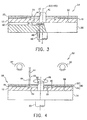
- Fig. 3 is a cross-sectional view showing a structure of the turntable and the optical disc according to the embodiment of the invention, and shows a status immediately after the sheet is loaded onto the disc substrate through the ultraviolet curing adhesive;
- Fig. 4 is a cross-sectional view showing a structure of the ultraviolet ray irradiation apparatus and the optical disc according to the embodiment of the invention, and shows a status when ultraviolet rays irradiate the ultraviolet curing adhesive;
- Fig. 5 is a cross-sectional view showing a structure of the ultraviolet ray irradiation apparatus and the optical disc according to the embodiment of the invention, and shows a status where the non-adhered portion is removed from the sheet after the ultraviolet curing adhesive is cured;
- Fig. 6 a perspective view showing an optical disc according to the second embodiment of the invention.
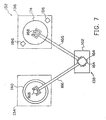
- Fig. 7 shows an disc making apparatus for making an optical disc according to the second embodiment
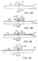
- Figs. 8A ⁇ 8D are side views showing the multi-layered disc and the turntable of the spin coater, and show a process for making the multi-layered disc on the turntable;
- Fig. 9 is a side view showing the transporting apparatus and the turntable for the multi-layered disc according to the second embodiment of the invention.
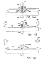
- Figs. 10A ⁇ 10C are side views showing the transporting apparatus and the ultraviolet ray irradiation apparatus for the multi-layered disc according to the second embodiment of the invention.
- the first embodiment of the invention relates to the method for manufacturing an optical disc.
- Fig. 1 shows an optical disc according to the first embodiment of the invention.
- the optical disc 10 can record information with a high density like a conventional optical disc, such as a DVD-R.
- the laser beam for recording and reproducing uses a bluish purple laser beam with a short wavelength, and the numerical aperture NA to the objective lens of the recording/reproducing device increases up to about 0.85.
- the recording capacity of a single-side disc for a 12cm optical disc 10 is increased up to about 22.5 GB (giga bytes).
- the optical disc 10 comprises a disc substrate 12 formed in a circular disc shape, a recording layer 18 layered on the disc substrate 12, and a transparent cover layer 20 covering the recording layer 12.
- the recording layer 18 is layered by a light reflection layer 16 and a light absorption layer 14.
- the cover layer 20 is composed of a sheet 22 (described later) that is adhered to the disc substrate 12 through the recording layer 18 by an ultraviolet curing adhesive 24.
- a circular center hole 26 is formed by penetrating the disc substrate 12 along a rotational center of the optical disc 10, the axial center SD.
- a circular opening 28 with a diameter larger than the center hole 26 is also formed on the center portion of the cover layer centered on the axial center SD.
- a ring groove 30 is formed on the inner circumference of the recording layer 18 along the circumferential direction centered on the axial center SD.
- the disc substrate is formed by molding, using resin material such as the polycarbonate (PC).
- the mold (not shown) for molding to form the disc substrate 12 comprises a main body having a circular concave cavity corresponding to the shape of the disc substrate 12 thereon, and a stamper with a circular-plate shape for transcribing to form a guiding groove on the recording surface 13 on the disc substrate 12.
- the stamper has a structure supported by a retainer of the mold formation apparatus.
- a protrusion with a ring shape corresponding to the groove 30 is formed on the stamper or the retainer.
- the sheet 22 forming the cover layer 20 is made of a thin film of transparent resin, such as polycarbonate (PC), polyethylene terephthalate (PET).
- a position determining hole 32 with a circular shape having the same diameter as the central hole 26 on the disc substrate 12 is formed by penetrating through the central portion of the sheet 22, referring to Fig. 3.
- the thickness of the thin film as the material of the sheet 22 is selected from a range of 30 ⁇ m ⁇ 150 ⁇ m.
- Fig. 2 shows an adhesion process in the method for manufacturing the optical disc according to the embodiment of the invention.
- the spin coater 34 as shown in Fig. 2, has a turntable 36, which is a thick circular plate.
- the upper surface of the turntable 36 is used as a loading surface 38 for loading the disc substrate 12.
- a cylindrical boss 40 stands on the central portion of the loading surface 38.
- the outer diameter of the boss 40 is a little smaller than the inner diameter of the central hole 26 on the disc substrate 12.
- a rotational shaft 42 under the central portion of the turntable 36 is coaxially connected to the turntable 36, and the rotational shaft 42 is directly connected to a driving motor (not shown), or through a torque transmission mechanism.
- a ring attraction groove 44 is formed on the inner circumference of the loading surface of the turntable 36 along the circumferential direction centered on the axial center ST of the turntable 36.
- a concave running groove 46 is formed outside the attraction groove 44 along the circumferential direction and has a width wider than that of the attraction groove 44.
- the attraction groove 44 is connected to a vacuum generating device (not shown), such as a vacuum pump, through a connection path with a pipe shape installed in the turntable 36.
- the vacuum generating device provides a negative pressure in the attraction groove 44 when the turntable 36 rotates, so that the disc substrate 12 can be sucked and fixed on the loading surface 38.
- the running groove 46 on the loading surface 38 makes the region corresponding to the recording layer 18 to not be in contact with the loading surface 38, so that it prevents this region from being damaged, and prevents foreign articles, such as dust, from being adhered on this region.
- the ultraviolet curing adhesive 24 is supplied to the recording surface 13 on the disc substrate 12 by a nuzzle dispenser 50 that is an adhesive supplier, as shown in Fig. 2B.
- a nuzzle dispenser 50 that is an adhesive supplier, as shown in Fig. 2B.
- the position of the dispenser 50 is adjusted to locate at an outer side from the groove 30 by a preset distance along the radial direction.
- the turntable rotates at a low speed and the ultraviolet curing adhesive 24 is dropped from the dispenser 50.
- the dispenser 50 can move along the circumferential direction and the ultraviolet curing adhesive 24 is dropped from the dispenser 50. In this way, the ultraviolet curing adhesive 24 dropped from the dispenser 50 becomes a ring shape at the outer side from the groove 30 by a preset distance, and is adhered on the recording surface 13.
- the sheet 22 is slowly lowered to the disc substrate 12, and as shown in Fig. 2C, the boss 40 is inserted into the position determining hole 32 of the sheet 22. Therefore, the position is determined so that the sheet 22 and the turntable 36 are coaxial, i.e., the sheet 22 and the disc substrate 12 are concentric in the surface direction. Accordingly, the sheet 22 is loaded onto the disc substrate 12 via the ultraviolet curing adhesive 24. Due to the sheet 22, the ultraviolet curing adhesive 24 is pressed to spread to the inner side and outer sides respectively in the radial direction. At this time, the ultraviolet curing adhesive 24, which is pressed to spread by the sheet 22 towards the inner side, reaches at least the groove 30 on the disc substrate 12. In other words, the distance from the position where the ultraviolet curing adhesive is dropped on the disc substrate 12 to the groove 30 is smaller than the displacement of the ultraviolet curing adhesive 24 toward the inner side when pressed to spread by the sheet 22.
- the ultraviolet curing adhesive 24 is pressed by the sheet 22 to spread to the groove 30 so that the attraction opening (not shown) connected to the connection path 48 of the turntable 36 on the outer surface of the boss 40 is opened, and a negative pressure from the gap between the disc substrate 12 and the sheet 22 is supplied within a preset time. By the negative pressure, the ultraviolet curing adhesive 24 between the sheet 22 and the disc substrate 12 can be compulsorily attracted to the groove 30.
- the turntable 36 begins to rotate at a high speed.
- the disc substrate 12 and the sheet 22 are rotated together with the turntable 36.
- the ultraviolet curing adhesive 24 between the sheet 22 and the disc substrate 12 extends outwards by the centrifugal force, so that the ultraviolet curing adhesive 24 is thinned and therefore the thickness from the groove 30 to the outer circumference of the sheet 22 becomes substantially uniform.
- the surplus ultraviolet curing adhesive 24 between the disc substrate 12 and the sheet 22 is scattered outwards from the outer rim between the disc substrate 12 and the sheet 22, and then adhered on the peripheral of the turntable 36.
- the ultraviolet curing adhesive 24 Before the ultraviolet curing adhesive 24 is cured, the ultraviolet curing adhesive 24 has a sufficient fluidity and can be easily removed and recycled.
- a multi-layered disc 68 layered by the disc substrate 12 and the sheet 22 through the ultraviolet curing adhesive 24 before being cured is transferred to a turntable 54 of an ultraviolet ray irradiation apparatus 52 by a disc transporting apparatus (not shown).
- the disc transporting apparatus supports the multi-layered disc 68 from the underside, i.e., the disc substrate 12, and transfers the multi-layered disc 68 from the turntable 36 to the turntable 54 of the ultraviolet ray irradiation apparatus 52.
- the multi-layered disc 68 can be transported in such a way that no wrinkles are created on the sheet 22 as well as the sheet 22 being not shifted on the disc substrate 12.
- the turntable 36 of the spin coater 34 is detachable, and after finishing the spin coating, the multi-layered disc 68 can be transported to the ultraviolet ray irradiation apparatus 52 together with the turntable 36 loading the disc 68.
- the turntable 54 is installed in the ultraviolet ray irradiation apparatus 52.
- a cylindrical boss 58 is also stood at the central portion of a loading surface of the turntable 54.
- the boss 58 determines a position so that the multi-layered disc 68 loaded on the loading surface 56 is coaxial with the turntable 54.
- a rotational shaft 60 is connected to the central portion of the underside of the turntable 54.
- the turntable 54 is rotatably supported by the rotational shaft 60 and connected to a driving motor (not shown). As the multi-layered disc is loaded on the turntable 54, the turntable 54 is rotated at a low speed by the torque generated from the multi-layered disc 68 and the driving motor.
- ultraviolet lamps 62 each constituted of a light source and a reflector etc are arranged above the turntable 54 in the ultraviolet ray irradiation apparatus 52.
- the ultraviolet lamps 62 irradiate ultraviolet rays with a predetermined wavelength to the multi-layered disc 68. Most of the ultraviolet rays penetrate through the sheet 22 to the ultraviolet curing adhesive 24. Accordingly, a curing reaction of the ultraviolet curing adhesive 24 begins.
- the thinned ultraviolet curing adhesive 24 between the sheet 22 and the disc substrate 12 is completely cured (hardened).
- the cover layer 20 composed of the sheet 22 and the cured ultraviolet curing adhesive 24 is thus formed with a thickness below 150 ⁇ m.
- a cutting blade 64 is arranged above the turntable 54 in the ultraviolet ray irradiation apparatus 52.
- the cutting blade 64 is further connected to an operation shaft of a linear actuator (not shown) used as a driving source for a step motor etc.
- the linear actuator By the linear actuator, the cutting blade 64 is supported to be able to contact with the turntable 54.
- the cutting blade 64 is supported to a position corresponding to the groove 30 on the disc substrate 12 in the radial direction.
- the cutting blade 64 is supported so that the blade edge 66 is located at an inner side where it is slightly in from the inner circumference of the groove 30. However, it has to fine-tune the position in the radial direction of the blade edge 66 according to the shape of the blade edge 66 and the thickness of the sheet 22 etc.
- the cutting blade 64 is in standby above the turntable 54 that is rotated at a low speed by the linear actuator before the curing for the ultraviolet curing adhesive 24 in the multi-layered disc 68 is finished.
- the cutting blade 64 begins to be lowered by the linear actuator toward the turntable 54 loading the multi-layered disc 68 thereon.
- the linear actuator lowers the cutting blade 64 so that the blade edge 66 penetrates the sheet 22 in the thickness direction, but the blade edge 66 reaches a cutting position not reaching the recording surface 13 of the disc substrate 12.
- the cutting blade 64 keeps at the cutting position for an interval of at least one revolution of the turntable 54.
- the cutting blade is raised by the linear actuator and put in standby above the turntable 54.
- the turntable 54 stops rotating as the cutting blade 64 begins to rise.
- the non-adhered portion 23 of the sheet 22 that is located at a more inner side than the groove 30 is cut from the sheet 22 and the remaining inner circumference of the sheet 22 is adhered to the disc substrate 12.
- the non-adhered portion 23 is sucked by a negative pressure attraction unit of a sucker installed at the front end of a manipulator, and the non-adhered portion 23 is removed from the disc substrate 12 by the manipulator. Accordingly, as shown in Fig. 5, the opening 28 is formed on the sheet 22.
- the non-adhered portion 23 of the sheet 22 is cut and removed in the ultraviolet ray irradiation apparatus 52.
- the multi-layered disc 68 that the ultraviolet curing adhesive 24 has been completely cured can be transported from the ultraviolet ray irradiation apparatus 52 to a cutting apparatus, at which the non-adhered portion 23 is cut and removed from the sheet 22.
- the multi-layered disc 68 is loaded on a turntable to rotate, and then the sheet 22 can be cut by a cutting blade.
- the multi-layered disc 68 can be fixed and the cutting blade moves in the radial direction to cut the sheet 22.
- a cutting blade with a circular blade edge is pressed to the sheet 22, and the sheet 22 is pressed to be cut by the blade edge of the cutting blade so that the non-adhered portion 23 is cut away from the inner circumference.
- the sheet 22 can be cut by the heated cutting blade 64, and at the same time, the cut profile of the sheet 22 is melted and softened to work out a desired shape.
- a laser beam can be used for melting to cut the non-adhered portion 23 away from the sheet 22.
- notch grooves or intermittent cutting parts with dash lines etc are previously formed along the groove 30, and after the ultraviolet curing adhesive 24 is cured, the non-adhered portion 23 can be separated from the sheet only by the pressurization without using the cutting blade.
- the multi-layered disc 68 where the non-adhered portion 23 has been removed from the sheet 22 becomes the optical disc product 10 shown in Fig. 1. If necessary, the resin paint is applied and dried on a disc surface opposite to the cover layer 20 of the disc substrate 12, and then type of the optical disc, label etc are printed thereon. Afterwards, the shape and size are examined to obtain the optical disc as a commercial product.
- the ultraviolet curing adhesive 24 is supplied to the outer side of the groove 30 on the disc substrate 12, and the sheet 22 is loaded on the disc substrate 12 through the ultraviolet curing adhesive 24.
- the ultraviolet curing adhesive 24 between the sheet 22 and the disc substrate 12 is pressed by the sheet 22 to extend to the groove 30.
- the surplus ultraviolet curing adhesive 24 does not overflow easily toward the inner side of the groove 30.
- the ultraviolet curing adhesive 24 even though the ultraviolet curing adhesive 24 overflows toward the inner side of the groove 30, the ultraviolet curing adhesive 24 is kept between the non-adhered portion 23 of the sheet 22 and the disc substrate 12. Therefore, before the ultraviolet curing adhesive 24 is cured, when the ultraviolet curing adhesive 24 between the disc substrate 12 and the sheet 22 is extended toward the outer side by the spin coater, the non-adhered portion 23 can stop the ultraviolet curing adhesive 24 that overflows toward the inner side of the groove 30 from moving toward the surface of the multi-layered disc.
- the ultraviolet curing adhesive 24 between the disc substrate 12 and the sheet 22 is extended toward the outer side by the spin coater. After the ultraviolet curing adhesive 24 filled between the disc substrate 12 and the sheet 22 is cured by the irradiation of the ultraviolet rays, the non-adhered portion 23 of the sheet 22 extending to the outer side of the groove 30 is cut along the groove 30. By removing the non-adhered portion 23 from the disc substrate 12, the whole sheet 22 from the inner circumference to the outer circumference can be adhered onto the disc substrate 12 by the ultraviolet curing adhesive 24.
- the ultraviolet curing adhesive 24 As a result, in order to increase the NA corresponding to the high recording density, even though the sheet 22 is very thin and the strength (rigidity) of the sheet is reduced, because the whole sheet 22 from the inner circumference to the outer circumference can be adhered onto the disc substrate 12 by the ultraviolet curing adhesive 24, it can actually prevent the sheet 22 of the optical disc 10 from exfoliating off the disc substrate 12. In addition, on the surface of the optical disc, except for the ultraviolet curing adhesive 24 that is cured along the groove 30, the other ultraviolet curing adhesive 24 is not exposed to the disc surface, so that the appearance quality of the optical disc is very excellent.
- the method for transporting the multi-layered disc of the second embodiment is suitable for a manufacturing process for an optical disc where a thin sheet is loaded on a disc substrate through an adhesive and a cover layer composed of the sheet and the adhesive is formed.
- Fig. 6 shows an optical disc according to the second embodiment of the invention.
- the optical disc 110 has the same structure as the optical disc 10 shown in Fig. 1.
- the laser beam for recording and reproducing uses a bluish purple laser beam with a short wavelength, and the numerical aperture NA to the objective lens of the recording/reproducing device increases up to about 0.85.
- the recording capacity of a single-side disc for a 12cm optical disc 110 is increased up to about 22.5 GB.
- the opening 28, larger than the center hole 26 of the disc substrate 12 is formed on the sheet 22 that forms the cover layer 20 together with the ultraviolet curing adhesive.
- a center hole 130 having the same inner diameter as the center hole 128 of the disc substrate 112 is formed on the central portion of the sheet 124.
- the optical disc 110 has a disc substrate 112 formed in a circular disc shape.
- One surface of the disc substrate 112 serves as a recording surface 114.
- the recording layer 114 is sequentially layered by a light reflection layer 116 and a light absorption layer 118, and a recording layer 120 is formed by the light reflection layer 116 and the light absorption layer 118.
- a transparent cover layer 122 is formed on the disc substrate 112 to cover the recording layer 120.
- the cover layer 122 is formed by adhering the sheet 124 to the disc substrate 112 through the recording layer 120 by an ultraviolet curing adhesive 126.
- the disc substrate 112 is formed by molding, using resin material such as the polycarbonate (PC), and the sheet 124 forming the cover layer 124 is made of a thin film of transparent resin, such as polycarbonate (PC), polyethylene terephthalate (PET).
- the thickness of the thin film as the material of the sheet 22 is selected from a range of 30 ⁇ m ⁇ 150 ⁇ m.
- Fig. 7 shows a disc making apparatus for making an optical disc according to the second embodiment.
- the disc making apparatus comprises a spin coater 134, an ultraviolet ray irradiation apparatus 136 and a disc transporting apparatus 138.
- a thick circular turntable 140 is installed in the spin coater 134.
- a surface on the turntable 140 for loading the disc substrate 112 is used as a loading surface 142.
- a cylindrical boss 144 is installed by standing on the central portion of the loading surface 142 along the axial center ST 1 .
- the outer diameter of the boss 144 is slightly smaller than the inner diameter of the center hole 128 of the disc substrate 112.
- the boss 144 is inserter into the center hole 128 to determine a position where the disc substrate 112 and the turntable 140 are coaxial.
- a rotational shaft 146 under the central portion of the turntable 140 is coaxially connected to the turntable 140, and the rotational shaft 146 is directly connected to a driving motor (not shown), or through a torque transmission mechanism.
- a ring attraction groove 148 is formed on the inner side of the loading surface 142 of the turntable 140 along the circumferential direction centered on the axial center ST 1 of the turntable 140.
- a concave running groove 150 is formed outside the attraction groove 148 along the circumferential direction and has a width wider than that of the attraction groove 148.
- the attraction groove 148 is connected to a vacuum generating device (not shown), such as a vacuum pump, through a connection path with a pipe shape installed in the turntable 140.
- the vacuum generating device provides a negative pressure in the attraction groove 148 when the turntable 140 rotates, so that the disc substrate 112 can be sucked and fixed on the loading surface 142.
- the running groove 150 on the loading surface 142 makes the region corresponding to the recording layer 120 to not be in contact with the loading surface 142, so that it prevents this region from being damaged, and prevents foreign articles, such as dust, from being adhered on this region.
- the ultraviolet curing adhesive 126 is supplied to the recording surface 114 on the disc substrate 112 by a nuzzle dispenser 154 that is an adhesive supplier, as shown in Fig. 8B.
- a nuzzle dispenser 154 that is an adhesive supplier
- the position of the dispenser 154 is adjusted to be located at an outer side from the center hole 128 by a preset distance.
- the turntable 140 rotates at a low speed and the ultraviolet curing adhesive 126 is dropped from the dispenser 154.
- the dispenser 154 can move along the circumferential direction and the ultraviolet curing adhesive 126 is dropped from the dispenser 126.
- the ultraviolet curing adhesive 126 dropped from the dispenser 154 becomes a ring shape at the outer side from the center hole 128 by a preset distance, and then is adhered on the recording surface 114.
- the dispenser 154 can move along the circumferential direction and drop the ultraviolet curing adhesive 126 without rotating the turntable 140.
- the sheet 124 is slowly lowered to the disc substrate 112, and as shown in Fig. 8C, the boss 144 is inserted into the center hole 130 of the sheet 124. Therefore, the position is determined so that the sheet 124 and the turntable 140 are coaxial, and then the sheet 124 is loaded onto the disc substrate 112 via the ultraviolet curing adhesive 126. Accordingly, on the turntable 140, a multi-layered disc 156, which is composed of the disc substrate 112 having the recording layer 120 formed thereon and the sheet 124 on the disc substrate 112 through the ultraviolet curing adhesive 126, is formed. Additionally, by loading the sheet 124 onto the disc substrate 112, due to the sheet 124, the ultraviolet curing adhesive 126 is pressed to spread to the inner side and outer sides respectively.
- the supply amount and position of the ultraviolet curing adhesive 126 to the recording layer 114 from the dispenser 154 are set, so that ultraviolet curing adhesive 126 can be pressed to spread to a preset radial position at the inner portion of the disc substrate 112. Furthermore, the time from finishing the supply of the ultraviolet curing adhesive 126 on the recording layer 114 to loading the sheet 124 can be properly adjusted.
- the turntable 140 of the spin coater 134 begins to rotate at a high speed.
- the disc substrate 112 and the sheet 124 are rotated together with the turntable 140.
- the ultraviolet curing adhesive 126 between the sheet 124 and the disc substrate 112 extends outwards by the centrifugal force, so that the ultraviolet curing adhesive 126 is thinned and therefore the thickness between the disc substrate 112 and sheet 124 becomes substantially uniform.
- the surplus ultraviolet curing adhesive 126 between the disc substrate 112 and the sheet 124 is scattered outwards from the outer rim between the disc substrate 112 and the sheet 124, and then adhered onto the periphery of the turntable 140.
- the ultraviolet curing adhesive 126 Before the ultraviolet curing adhesive 126 is cured, the ultraviolet curing adhesive 126 has a sufficient fluidity and can be easily removed and recycled.
- three insertion holes 158 are formed on the outer surface of the boss 144 of the turntable 140 in the axial direction of the boss 144.
- the three insertion holes 158 extend from the top to the bottom of the boss 144, and are arranged at equal intervals (120°) along the circumferential direction centered on the axis ST 1 .
- a ring recess 160 is formed around the bottom of the boss 144 at the inner side of the attraction groove 148.
- the inner radius of the recess 160 is equal to a distance from the central axial ST 1 to the bottom of the insertion hole 158, but can be a little smaller than that distance.
- the outer radius of the recess 160 is larger than the radius of the center hole 128 of the disc substrate 112 by a preset length.
- the bottoms of the three insertion holes 158 are respectively coupled to the recess 160.
- a supporting stage 162 is installed on a common floor (not shown) of the spin coater 134 and the ultraviolet ray irradiation apparatus in the disc transporting apparatus 138.
- a rotational stage 164 capable of rotating, rising and lowering is installed on the supporting stage 162, and a driving unit (not shown) is also installed internally for driving the rotational stage 164 to rotate, rise and lower.
- the rotational stage 164 is connected to a base of a transporting arm 166, which is supported by the rotational stage 164 in a cantilever manner, and extends substantially in the horizontal direction.
- a disc connecting unit 168 substantially, a cylinder
- three fixers 170 protrude from the bottom of the disc connecting unit 168.
- the three fixers 170 are slender rods and are respectively supported by the disc connecting unit 168 in a way such that the longitudinal direction of the fixer 170 and the axis ST 1 of the turntable 140 are in parallel.
- the three fixers 170 are arranged at equal intervals of 120° along the circumferential direction.
- a claw 172 that is almost bent perpendicularly to the outer side is formed at the tip of each fixer 170.
- the three fixers 170 are supported by the disc connecting unit 168 and are movable along the radial direction centered on the central axis of the disc connecting unit 168.
- the three fixers 170 can be moved between a fixing position shown in solid line and a standby position shown in dash line by an actuator such as an electromagnetic solenoid installed in the disc connecting unit 168.
- the disc transporting apparatus 138 transports the multi-layered disc 156 from the turntable 140 of the spin coater 134 to the ultraviolet ray irradiation apparatus 136.
- the position of the rotational stage 164 is first adjusted in the rotational direction and in the up-and-down direction, so that the center of the disc connecting unit 168 and the axis ST 1 of the turntable 140 is consistent, and the lower ends of the fixers 170 are kept above the multi-layered disc 156 on the turntable 140.
- the transporting arm 166 and the disc connecting unit 168 together with the rotational stage 164 are lowered, so that the three fixers 170 at the standby position shown in dashed line are respectively inserted into the three insertion holes 185 in the boss 144.
- the rotational stage 164 is lowered to a position where the claws 172 of the fixers 170 protrude from the underside of the disc substrate 112 through the center holes 128, 130.
- the fixers 170 protrude from the underside of the disc substrate 112 without being in contact with the turntable 140.
- the disc transporting apparatus 138 moves the fixers 170 from the standby position shown in solid line to the fixing position shown in dashed line by the disc connecting unit 168.
- the underside of the disc substrate 112 is fixed by the claws 172 of the three fixers 170 respectively.
- the rotational stage 164 is raised, and the multi-layered disc 156 whose disc substrate 112 is fixed by the fixers 170 is raised together with the disc connecting unit 168 so that the multi-layered disc 156 is lifted up above the turntable 140.
- the disc transporting apparatus 138 rotates the rotational stage 164 towards the ultraviolet ray irradiation apparatus 136 (clockwise direction in Fig. 7), and the disc connecting unit 168 is moved to above the turntable 174 of the ultraviolet ray irradiation apparatus 136.
- the position of the rotational stage 164 is also adjusted in the rotational direction, so that the center of the disc connecting unit 168 is consistent with the axis ST 2 of the turntable 174.
- a boss 178 is installed in a stand manner on the turntable 174 of the ultraviolet ray irradiation apparatus 136 for determining the position of the multi-layered disc 156. Similar to the boss 144 of the spin coater 134, three insertion holes 180 are formed on the outer surface of the boss 178. In addition, similar to the turntable 140 of the spin coater 134, a ring recess 182 is formed on the loading surface 176 of the turntable 174 around the bottom of the boss 178.
- the rotational stage 164 is lowered together with the disc connecting unit 168.
- the multi-layered disc 156 hung by the fixers 170 below the disc connecting unit 168 is then loaded onto the loading surface 176 of the turntable 174.
- the three fixers 170 fixing the multi-layered disc 156 go down through the insertion holes 180 on the boss 178.
- the tips of the fixers 170 insert into the recess 182 of the turntable 174. Therefore, the disc connecting unit 168 can load the multi-layered disc 156 onto the turntable 174, wherein the three fixers 170 are not in contact with the boss 178 and the turntable 174.
- the disc connecting unit 168 is raised together with the rotational stage 164, and the fixers are withdrawn from the center holes 128, 130 and detached from the multi-layered disc 156.
- the distance from the rotational shaft of the rotational stage 164 to the central axis ST 1 of the turntable 140 is consistent with the distance from the rotational shaft of the rotational stage 164 to the central axis ST 2 of the turntable 174.
- the central axis of the disc connecting unit 168 can be consistent with the axis ST 1 and the axis ST 2 .
- the transporting arm 166 can be expanded or contracted in its longitudinal direction, and the length of the transporting arm 166 can be adjusted while the transporting arm 166 rotates, so that the central axis of the disc connecting unit 168 can be consistent with the axis ST 1 and the axis ST 2 .
- the supporting stage 162 itself can move forward and backward in the horizontal direction, and the distance from the supporting stage 162 to the spin coater 134 and the ultraviolet ray irradiation apparatus 136 can be adjusted while the transporting arm 166 rotates, so that the central axis of the disc connecting unit 168 can be consistent with the axis ST 1 and the axis ST 2 .
- a rotational shaft 184 is connected to the central portion under the turntable 174 of the ultraviolet ray irradiation apparatus 136.
- the turntable 174 is rotatably supported by rotational shaft 184, and additionally, the turntable 174 is directly connected to a step motor (not shown), or through a torque transmission mechanism.
- the insertion holes 158, 180 can have a phase consistent with the fixers 170, so that the turntables 140, 174 can be always stopped from rotating.
- ultraviolet lamps 186 are arranged above the turntable 174 in the ultraviolet ray irradiation apparatus 136.
- the ultraviolet lamps 186 irradiate ultraviolet rays with a predetermined wavelength to the multi-layered disc 156 on the turntable 174.
- the ultraviolet rays penetrate through the sheet 124 on the multi-layered disc 156 to the ultraviolet curing adhesive 126. Accordingly, a curing reaction of the ultraviolet curing adhesive 126 begins.
- the thinned ultraviolet curing adhesive 126 between the sheet 124 and the disc substrate 112 is completely cured (hardened).
- the sheet 124 is adhered to the disc substrate 112, and at the same time, the cover layer 122 composed of the sheet 124 and the cured ultraviolet curing adhesive 126 is thus formed.
- the multi-layered disc 156 whose ultraviolet curing adhesive 126 has been completely cured becomes an optical disc product 110 shown in Fig. 6.
- the optical disc 110 is transported to a transporting device such as a conveyer from the turntable 174, and then the optical disc 110 is transported by the transporting device to a storage room for temporary storage, or to a printing device for a printing label etc.
- the disc transporting apparatus 138 can be used for transporting the optical disc 110.
- a transporting apparatus other than the disc transporting apparatus 138 can also be for transporting.
- the multi-layered disc 156 where the sheet is loaded onto the disc substrate 112 through the ultraviolet curing adhesive is transported from the turntable 140 to the turntable 174 by the disc transporting apparatus 138 before the ultraviolet curing adhesive between the sheet 124 and the disc substrate 112 is cured, the disc substrate 112 is fixed by the fixers 170 and the loading weight of the multi-layered disc is supported by the fixers 170.
- the loading weight from the disc transporting apparatus 138 does not directly act on the sheet when transporting the multi-layered disc 156. Therefore, it can prevent the sheet 124 of the multi-layered disc 156 from wrinkles due to the loading weight of the disc transporting apparatus 138, and also prevent the sheet 124 from local exfoliations on the disc substrate 112.
- the multi-layered disc 156 is transported from the turntable 140 of the spin coater 134 to the turntable 174 of the ultraviolet ray irradiation apparatus, but the positions before or after transporting the multi-layered disc 156 are not limited. If the method for transporting the multi-layered disc 156 is suitable, even though the multi-layered disc 156 is lifted up to transport before the ultraviolet curing adhesive 126 is cured, it can also prevent wrinkles or exfoliations from occurring on the sheet of the multi-layered disc 156 when transporting. Moreover, the method for transporting the multi-layered disc of the second embodiment is also suitable for transporting the optical disc 10 in Fig. 1 from the turntable 36 of the spin coater 34 to another apparatus or place, such as the ultraviolet ray irradiation apparatus 52 etc.
- the inner circumference of the disc substrate 112 is fixed by three fixers 170 and the disc connecting unit 168 is connected to the disc substrate 112.
- the outer circumference of the disc substrate 112 can be fixed by plural fixers each having a claw that protrudes inwards and the disc connecting unit 168 is connected to the disc substrate 112.
- the disc connecting unit 168 does not have to directly connect to the disc substrate 112.
- the turntable 140 of the spin coater 140 can be attachable, by which the turntable 140 can be fixed by fixers and the disc connecting unit 168 is indirectly connected to the disc substrate 112.
- any one of the configurations where the disc connecting unit 168 is connected to the disc substrate 112 and the structure of the disc connecting unit 168 can be used.
- the disc transporting apparatus 138 uses an arm-type device having the transporting arm 166 capable of rising, lowering and rotating.
- the structure of the disc transporting apparatus is not limited to the arm-type device.
- the disc transporting apparatus can have a carrier capable of moving in two dimensions above the spin coater 134 and the ultraviolet ray irradiation apparatus 136, and a crane that is installed on the carrier to make the disc connecting unit be able to move in the up-and-down direction.
- the disc substrate of the optical disc is formed by molding using a material of polycarbonate (PC), with a thickness of 1.2mm, an outer radius of 120mm.
- a guiding groove with a groove depth of 175nm, a groove width of 500nm and a track pitch of 1600nm is formed on the recording surface of the disc substrate.
- a silver film with a thickness of 80nm is used as a light reflection layer and is formed on the recording surface by a magnetron sputter.
- a thin film made of PET with a thickness of 62 ⁇ m is used as the sheet and is made to have the same surface shape as the disc substrate.
- a ring groove is formed on the inner side of the recording layer at the recording surface (inner ring groove).
- the inner ring groove is equivalent to the groove 30 of the optical disc 10 shown in Figs. 1 ⁇ 5.
- the above disc substrate is loaded onto the turntable of the spin coater.
- the turntable rotates at a low speed of 60rpm and the ultraviolet curing adhesive is dropped to the recording surface of the disc substrate.
- the ultraviolet curing adhesive is then adhered to the inner side of the inner ring groove at the recording surface, and becomes a ring shape.
- the sheet is loaded onto the disc substrate through the ultraviolet curing adhesive. After the ultraviolet curing adhesive is pressed by the sheet to spread to the inner ring groove, the turntable rotates at a high speed of 4400rpm, so that the ultraviolet curing adhesive between the sheet and the disc substrate is extended to the outer side by the centrifugal force, and the surplus ultraviolet curing adhesive is scattered to the outer side of the multi-layered disc.
- the disc connecting unit of the disc transporting apparatus is coupled to the disc substrate of the multi-layered disc, the multi-layered disc is then transported from the turntable of the spin coater to the turntable of the ultraviolet ray irradiation apparatus.
- the turntable is rotated at a low speed and the ultraviolet rays from the ultraviolet lamps irradiate so that the ultraviolet curing adhesive between the sheet and the disc substrate is cured.
- the sheet is cut by a cutting blade along the inner ring groove on the recording surface to form a circular opening, and the non-adhered portion of the sheet located at the inner side of the inner ring groove is removed from the disc substrate.
- the sheet of the optical disc made by the above process can be uniformly adhered onto the disc substrate, and therefore local exfoliations on the sheet and the ultraviolet curing adhesive adhered on the surface of the cover layer will not be observed.
- the sheet has the same shape as the sheet that is cut to form the opening in example 1.
- the disc substrate is loaded onto the turntable and the ultraviolet curing adhesive is supplied to the recording surface of the disc substrate. At this time, the amount and the supply position of the ultraviolet curing adhesive in the radial direction with respect to the disc substrate are the same as the example 1.
- the sheet is loaded onto the disc substrate through the ultraviolet curing adhesive, and the ultraviolet curing adhesive is pressed by the sheet to spread to the inner side. However, the ultraviolet curing adhesive is not uniformly spread to the inner side of the sheet.
- the turntable of the spin coater is rotated under the same condition as the example 1, and the ultraviolet curing adhesive is extended to the outer side by the centrifugal force. As a result, the surplus ultraviolet curing adhesive is scattered to the outer side of the multi-layered disc.
- the disc connecting unit of the disc transporting apparatus is coupled to the disc substrate of the multi-layered disc, the multi-layered disc is then transported from the turntable of the spin coater to the turntable of the ultraviolet ray irradiation apparatus.
- the turntable is rotated at a low speed and the ultraviolet rays from the ultraviolet lamps irradiate so that the ultraviolet curing adhesive between the sheet and the disc substrate is cured.
- the optical disc in the comparison example 1 because the non-adhered portion on the inner circumference of the sheet can seen by the naked eye, the appearance quality is worse than that of the optical disc made by the example 1. In addition, if the optical disc made by the comparison example 1 is repeatedly loaded to an optical disc apparatus, exfoliations occur from the inner circumference of the sheet.
- the sheet has the same shape as the sheet that is cut to form the opening in the example 1.
- the disc substrate is loaded onto the turntable and the ultraviolet curing adhesive is supplied to the recording surface of the disc substrate.
- the amount of the ultraviolet curing adhesive in the radial direction with respect to the disc substrate is the same as the example 1, but the supply position of the ultraviolet curing adhesive in the radial direction with respect to the disc substrate is displaced inward with respect to the supply position in the example 1.
- the ultraviolet curing adhesive is pressed by the sheet to spread to the inner side.
- the surplus ultraviolet curing adhesive is slightly overflowed to the inner side from between the sheet and the disc substrate.
- the turntable of the spin coater is rotated under the same condition as example 1, and the ultraviolet curing adhesive is extended to the outer side by the centrifugal force. As a result, the surplus ultraviolet curing adhesive is scattered to the outer side of the multi-layered disc.
- the disc connecting unit of the disc transporting apparatus is coupled to the disc substrate of the multi-layered disc, the multi-layered disc is then transported from the turntable of the spin coater to the turntable of the ultraviolet ray irradiation apparatus.
- the turntable is rotated at a low speed and the ultraviolet rays from the ultraviolet lamps irradiate so that the ultraviolet curing adhesive between the sheet and the disc substrate is cured.
- the ultraviolet curing adhesive that overflows to the inner side from between the sheet and the disc substrate will adhere radially on the disc surface centered on the center hole.
- the ultraviolet curing adhesive that adheres on the disc surface due to the irradiation of the ultraviolet rays becomes radial blots. Therefore, the appearance quality of the optical disc of the comparison example 2 is worse than that of the optical disc of the example 1.
- the radial bolts formed due to the ultraviolet curing adhesive will create diffusion and degradation of the laser beam, which are reasons for the occurrence of the recording/reproducing errors for the optical disc.
- the sheet and the disc substrate used are the same as example 1.
- the disc substrate is loaded onto the turntable and the ultraviolet curing adhesive is supplied to the recording surface of the disc substrate.
- the amount and the supply position of the ultraviolet curing adhesive in the radial direction with respect to the disc substrate are the same as example 1.
- the sheet is loaded onto the disc substrate through the ultraviolet curing adhesive, and the ultraviolet curing adhesive is pressed by the sheet to spread to the inner side.
- the turntable of the spin coater is rotated under the same condition as example 1, and the ultraviolet curing adhesive is extended to the outer side by centrifugal force. As a result, the surplus ultraviolet curing adhesive is scattered to the outer side of the multi-layered disc.
- the disc connecting unit of the disc transporting apparatus is coupled to the disc substrate of the multi-layered disc, the multi-layered disc is then transported from the turntable of the spin coater to the turntable of the ultraviolet ray irradiation apparatus.
- the turntable is rotated at a low speed and the ultraviolet rays from the ultraviolet lamps irradiate so that the ultraviolet curing adhesive between the sheet and the disc substrate is cured.
- the sheet is cut by a cutting blade along the inner ring groove on the recording surface to form a circular opening, and the non-adhered portion of the sheet located at the inner side of the inner ring groove is removed from the disc substrate.
- the ultraviolet curing adhesive adhered onto the surface of the cover layer is not observed, but exfoliations occur in the vicinity of the portion sucking the sheet. As a result, air enters between the sheet and the disc substrate at the exfoliated portions.
- the sheet from the inner circumference to the outer circumference can be simply adhered onto the disc substrate by the adhesive. Additionally, when adhering the sheet, the invention can prevent the surplus adhesive from being adhered to the disc surface from damaging the quality.
- the multi-layered disc can be transported before the adhesive between the disc substrate and the sheet is cured without creating wrinkles and exfoliations on the sheet.
Landscapes
- Engineering & Computer Science (AREA)
- Mechanical Engineering (AREA)
- Physics & Mathematics (AREA)
- Electromagnetism (AREA)
- Health & Medical Sciences (AREA)
- Toxicology (AREA)
- Chemical & Material Sciences (AREA)
- Chemical Kinetics & Catalysis (AREA)
- General Chemical & Material Sciences (AREA)
- Manufacturing & Machinery (AREA)
- Manufacturing Optical Record Carriers (AREA)
- Optical Record Carriers And Manufacture Thereof (AREA)
Abstract
Description
Claims (7)
- A method for manufacturing an optical disc, wherein an information recording layer is formed between a disc substrate and a transparent cover layer thinner than the disc substrate, and the cover layer is formed by adhering a transparent sheet to the disc substrate by an adhesive, so as to form the optical disc, the method comprising the steps of:forming a ring groove at an inner side of an information recording region in the information recording layer formed on the disc substrate;supplying the adhesive to an outer side of the ring groove on the disc substrate;loading the sheet onto a region from the outer side of the information recording region to the inner side of the ring groove;extending the adhesive between the sheet and the disc substrate from the ring groove to the outer side of the sheet in a radial direction; andcutting a non-adhered portion of the sheet that extends towards the inner side of the ring groove after the adhesive is cured, so as to remove the non-adhered portion from the disc substrate.
- The method of claim 1, wherein a thickness of the sheet is between 30µm∼150µm.
- The method of claim 1, wherein after the sheet is loaded on the disc substrate through the adhesive, the disc substrate and the sheet are rotated in a circumferential direction of the disc substrate, so that the adhesive is extended to the outer side.
- The method of claim 1, wherein an ultraviolet curing adhesive is used as the adhesive filled between the disc substrate and the sheet, and the adhesive is filled to the outer side of the ring groove between the disc substrate and the sheet, after the adhesive is extended to the outer side, the adhesive between the sheet and the disc substrate is irradiated by ultraviolet rays to cure.
- A method for transporting a multi-layered disc, in a process to make an optical disc, wherein an information recording layer is formed between a disc substrate and a transparent cover layer thinner than the disc substrate, and the cover layer is formed by adhering a transparent sheet to the disc substrate by an adhesive, so as to form the optical disc, the method comprising:in order to lift up the multi-layered disc, that has the sheet loaded onto the disc substrate through the adhesive before the adhesive between the disc substrate and the sheet is cured, to transport by a transporting apparatus for transporting the multi-layered disc, the transporting apparatus is connected to the disc substrate of the multi-layered disc, a loading weight of the multi-layered disc being supported by the transporting apparatus through the disc substrate, and the multi-layered disc is lifted up and transported by the transporting apparatus.
- The method of claim 5, wherein in the transporting apparatus, when transporting the multi-layered disc, a plurality of fixers is inserted into a center hole penetrating through the disc substrate, a circumference of the center hole is fixed by the fixers so that the transporting apparatus is connected to the disc substrate.
- The method of claim 5, wherein an ultraviolet curing adhesive is used as the adhesive for adhering the sheet to the disc substrate, and the transporting apparatus transports the multi-layered disc from a turntable of a spin coater to an ultraviolet ray irradiation apparatus.
Priority Applications (1)
| Application Number | Priority Date | Filing Date | Title |
|---|---|---|---|
| EP08017908A EP2017838A1 (en) | 2001-06-07 | 2002-06-06 | Method for transporting multi-layered optical disc |
Applications Claiming Priority (6)
| Application Number | Priority Date | Filing Date | Title |
|---|---|---|---|
| JP2001172795 | 2001-06-07 | ||
| JP2001172795 | 2001-06-07 | ||
| JP2001177407 | 2001-06-12 | ||
| JP2001177407 | 2001-06-12 | ||
| JP2002110394A JP2003067991A (en) | 2001-06-07 | 2002-04-12 | Optical disc manufacturing method and disc stack conveying method |
| JP2002110394 | 2002-04-12 |
Related Child Applications (1)
| Application Number | Title | Priority Date | Filing Date |
|---|---|---|---|
| EP08017908A Division EP2017838A1 (en) | 2001-06-07 | 2002-06-06 | Method for transporting multi-layered optical disc |
Publications (2)
| Publication Number | Publication Date |
|---|---|
| EP1265236A2 true EP1265236A2 (en) | 2002-12-11 |
| EP1265236A3 EP1265236A3 (en) | 2008-06-18 |
Family
ID=27346895
Family Applications (2)
| Application Number | Title | Priority Date | Filing Date |
|---|---|---|---|
| EP08017908A Withdrawn EP2017838A1 (en) | 2001-06-07 | 2002-06-06 | Method for transporting multi-layered optical disc |
| EP02012390A Withdrawn EP1265236A3 (en) | 2001-06-07 | 2002-06-06 | Method for manufacturing optical disc and method for transporting multi-layered optical disc |
Family Applications Before (1)
| Application Number | Title | Priority Date | Filing Date |
|---|---|---|---|
| EP08017908A Withdrawn EP2017838A1 (en) | 2001-06-07 | 2002-06-06 | Method for transporting multi-layered optical disc |
Country Status (5)
| Country | Link |
|---|---|
| US (1) | US7001474B2 (en) |
| EP (2) | EP2017838A1 (en) |
| JP (1) | JP2003067991A (en) |
| CN (2) | CN1209764C (en) |
| TW (1) | TW591656B (en) |
Cited By (1)
| Publication number | Priority date | Publication date | Assignee | Title |
|---|---|---|---|---|
| US12329490B2 (en) * | 2020-04-21 | 2025-06-17 | Murata Manufacturing Co., Ltd. | Conversion adapter |
Families Citing this family (4)
| Publication number | Priority date | Publication date | Assignee | Title |
|---|---|---|---|---|
| US7279069B2 (en) * | 2002-07-18 | 2007-10-09 | Origin Electric Company Limited | Adhesive curing method, curing apparatus, and optical disc lamination apparatus using the curing apparatus |
| JP2005085302A (en) * | 2003-09-04 | 2005-03-31 | Tdk Corp | Manufacturing method for optical recording medium |
| JP2006185466A (en) * | 2004-12-24 | 2006-07-13 | Fuji Photo Film Co Ltd | Sticking device and method |
| JP4580444B2 (en) * | 2006-09-27 | 2010-11-10 | 芝浦メカトロニクス株式会社 | Film cutting apparatus and film cutting method |
Family Cites Families (15)
| Publication number | Priority date | Publication date | Assignee | Title |
|---|---|---|---|---|
| JPH01131337A (en) | 1987-11-13 | 1989-05-24 | Nissin Kogyo Kk | Lining for brake and manufacture thereof |
| JPH04105892A (en) * | 1990-08-23 | 1992-04-07 | Shin Meiwa Ind Co Ltd | Disk transferrer |
| US5681634A (en) * | 1995-02-15 | 1997-10-28 | Matsushita Electric Industrial Co., Ltd. | Optical information medium, and method and apparatus for fabricating the same |
| US5744193A (en) * | 1995-05-20 | 1998-04-28 | Kitano Engineering Co., Ltd. | Method of manufacturing an optical disc and a placing platform to be used by the same |
| US5951806A (en) * | 1995-11-30 | 1999-09-14 | Kitano Engineering Co., Ltd. | Method of manufacturing a storage disc |
| DE69731707T2 (en) * | 1996-07-31 | 2006-03-02 | Kitano Engineering Co., Ltd., Komatsushima | Method for correcting the unequal position of an information disc |
| JP4099549B2 (en) * | 1997-05-16 | 2008-06-11 | ソニー株式会社 | Optical recording medium and optical disk device |
| MY121289A (en) * | 1997-05-30 | 2006-01-28 | Matsushita Electric Industrial Co Ltd | Method and apparatus for manufacturing optical disk |
| JP3725344B2 (en) * | 1998-05-11 | 2005-12-07 | オリジン電気株式会社 | Optical disk laminating method and apparatus |
| EP1083557A4 (en) * | 1999-03-23 | 2005-04-13 | Dainippon Ink & Chemicals | DEVICE FOR PRODUCING OPTICAL PLATES |
| US6594330B1 (en) | 1999-10-26 | 2003-07-15 | Agere Systems Inc. | Phase-locked loop with digitally controlled, frequency-multiplying oscillator |
| JP2001172795A (en) | 1999-12-14 | 2001-06-26 | Ulvac Kyushu Corp | Aluminum composite and method for surface-treating aluminum composite |
| TW527590B (en) * | 2000-04-25 | 2003-04-11 | Matsushita Electric Industrial Co Ltd | Compact disk, and the manufacturing method of the same, and the manufacturing device of compact disk |
| JP3516632B2 (en) * | 2000-04-27 | 2004-04-05 | オリジン電気株式会社 | Method and apparatus for bonding optical disk substrates |
| JP2002110394A (en) | 2000-09-29 | 2002-04-12 | Casio Comput Co Ltd | Light source device |
-
2002
- 2002-04-12 JP JP2002110394A patent/JP2003067991A/en active Pending
- 2002-04-26 TW TW091108644A patent/TW591656B/en not_active IP Right Cessation
- 2002-06-06 EP EP08017908A patent/EP2017838A1/en not_active Withdrawn
- 2002-06-06 CN CNB021218315A patent/CN1209764C/en not_active Expired - Fee Related
- 2002-06-06 EP EP02012390A patent/EP1265236A3/en not_active Withdrawn
- 2002-06-06 CN CNB2004100889869A patent/CN100373482C/en not_active Expired - Fee Related
- 2002-06-07 US US10/165,406 patent/US7001474B2/en not_active Expired - Fee Related
Cited By (1)
| Publication number | Priority date | Publication date | Assignee | Title |
|---|---|---|---|---|
| US12329490B2 (en) * | 2020-04-21 | 2025-06-17 | Murata Manufacturing Co., Ltd. | Conversion adapter |
Also Published As
| Publication number | Publication date |
|---|---|
| JP2003067991A (en) | 2003-03-07 |
| EP1265236A3 (en) | 2008-06-18 |
| CN1209764C (en) | 2005-07-06 |
| US20020185219A1 (en) | 2002-12-12 |
| CN1641767A (en) | 2005-07-20 |
| EP2017838A1 (en) | 2009-01-21 |
| CN100373482C (en) | 2008-03-05 |
| US7001474B2 (en) | 2006-02-21 |
| CN1426057A (en) | 2003-06-25 |
| TW591656B (en) | 2004-06-11 |
Similar Documents
| Publication | Publication Date | Title |
|---|---|---|
| KR100469217B1 (en) | Method of manufacturing disk substrate, and method and device for manufacturing optical disk | |
| US7001474B2 (en) | Method for manufacturing optical disc and method for transporting multi-layered optical disc | |
| JP2002316084A (en) | Spin coating apparatus using mask and mask for spin coating | |
| JP4076120B2 (en) | Spin coating method and apparatus | |
| CN101223592B (en) | Optical recording medium manufacturing method and manufacturing device | |
| JP3981625B2 (en) | Optical recording disk manufacturing method and optical recording disk manufacturing system | |
| TW579303B (en) | Spin coating method and apparatus, and mask used in the same method and apparatus | |
| CN101019179A (en) | Method of manufacturing optical information recording medium | |
| JP2004164802A (en) | Manufacturing method of optical recording disk | |
| KR20050005469A (en) | Multi-layer recording medium forming method and device, and multi-layer recording medium | |
| JP2004134050A (en) | Method for forming cover layer of optical disk | |
| JP2003006937A (en) | Method for producing stuck optical disk | |
| JP3126267U (en) | Optical disc manufacturing equipment | |
| JP4719096B2 (en) | Optical recording medium manufacturing method and manufacturing apparatus | |
| JP4640255B2 (en) | Optical recording medium manufacturing method and manufacturing apparatus | |
| JP2002260301A (en) | Method for manufacturing bonded optical disk, and disk supporting base used therefor | |
| JP3983567B2 (en) | Manufacturing method of optical information recording medium | |
| JP2006318610A (en) | Device and method for sticking | |
| JP2002001198A (en) | Spin coater and method of manufacturing information recording medium | |
| JP2008052790A (en) | Spin coating apparatus, disk manufacturing apparatus, and optical disk recording medium | |
| HK1119826B (en) | Process for producing optical recording medium and apparatus therefor | |
| JP2004164727A (en) | Method for manufacturing optical recording medium | |
| JP2007157309A (en) | Optical disc manufacturing method, spin coating apparatus, and optical disc manufacturing apparatus | |
| JP2005353152A (en) | Disk manufacturing apparatus and method | |
| TW200306566A (en) | Optical data recording medium and method for manufacturing the same |
Legal Events
| Date | Code | Title | Description |
|---|---|---|---|
| PUAI | Public reference made under article 153(3) epc to a published international application that has entered the european phase |
Free format text: ORIGINAL CODE: 0009012 |
|
| AK | Designated contracting states |
Kind code of ref document: A2 Designated state(s): AT BE CH CY DE DK ES FI FR GB GR IE IT LI LU MC NL PT SE TR |
|
| AX | Request for extension of the european patent |
Free format text: AL;LT;LV;MK;RO;SI |
|
| RAP1 | Party data changed (applicant data changed or rights of an application transferred) |
Owner name: FUJIFILM CORPORATION |
|
| RIC1 | Information provided on ipc code assigned before grant |
Ipc: B29C 65/52 20060101ALI20080306BHEP Ipc: G11B 7/26 20060101AFI20020916BHEP |
|
| PUAL | Search report despatched |
Free format text: ORIGINAL CODE: 0009013 |
|
| AK | Designated contracting states |
Kind code of ref document: A3 Designated state(s): AT BE CH CY DE DK ES FI FR GB GR IE IT LI LU MC NL PT SE TR |
|
| AX | Request for extension of the european patent |
Extension state: AL LT LV MK RO SI |
|
| 17P | Request for examination filed |
Effective date: 20080918 |
|
| 17Q | First examination report despatched |
Effective date: 20081205 |
|
| AKX | Designation fees paid |
Designated state(s): DE FR GB |
|
| STAA | Information on the status of an ep patent application or granted ep patent |
Free format text: STATUS: THE APPLICATION IS DEEMED TO BE WITHDRAWN |
|
| 18D | Application deemed to be withdrawn |
Effective date: 20090416 |