EP1264927A2 - Transportvorrichtung zum Transport von Reinigungmittel-Einheiten für eine Geschirrspülmaschine oder eine Textilwaschmaschine - Google Patents
Transportvorrichtung zum Transport von Reinigungmittel-Einheiten für eine Geschirrspülmaschine oder eine Textilwaschmaschine Download PDFInfo
- Publication number
- EP1264927A2 EP1264927A2 EP02010283A EP02010283A EP1264927A2 EP 1264927 A2 EP1264927 A2 EP 1264927A2 EP 02010283 A EP02010283 A EP 02010283A EP 02010283 A EP02010283 A EP 02010283A EP 1264927 A2 EP1264927 A2 EP 1264927A2
- Authority
- EP
- European Patent Office
- Prior art keywords
- conveyor belt
- transport device
- transport
- conveyor
- elements
- Prior art date
- Legal status (The legal status is an assumption and is not a legal conclusion. Google has not performed a legal analysis and makes no representation as to the accuracy of the status listed.)
- Withdrawn
Links
Images

Classifications
-
- A—HUMAN NECESSITIES
- A47—FURNITURE; DOMESTIC ARTICLES OR APPLIANCES; COFFEE MILLS; SPICE MILLS; SUCTION CLEANERS IN GENERAL
- A47L—DOMESTIC WASHING OR CLEANING; SUCTION CLEANERS IN GENERAL
- A47L15/00—Washing or rinsing machines for crockery or tableware
- A47L15/42—Details
- A47L15/44—Devices for adding cleaning agents; Devices for dispensing cleaning agents, rinsing aids or deodorants
- A47L15/4463—Multi-dose dispensing arrangements
-
- D—TEXTILES; PAPER
- D06—TREATMENT OF TEXTILES OR THE LIKE; LAUNDERING; FLEXIBLE MATERIALS NOT OTHERWISE PROVIDED FOR
- D06F—LAUNDERING, DRYING, IRONING, PRESSING OR FOLDING TEXTILE ARTICLES
- D06F39/00—Details of washing machines not specific to a single type of machines covered by groups D06F9/00 - D06F27/00
- D06F39/02—Devices for adding soap or other washing agents
- D06F39/026—Devices for adding soap or other washing agents the powder or tablets being added directly, e.g. without the need of a flushing liquid
Definitions
- the invention relates to a transport device for transport of detergent units for a dishwasher or a textile washing machine.
- DE 43 44 205 A1 discloses a detergent dosing device for a dishwasher, in which individual units of detergent of a certain shape are stored in a closed storage room and are fed to the washing process by means of an ejector.
- the individual cleaning agent units are stored in a row or stack arrangement in such a way that the individual cleaning agent units are each connected to at least one further cleaning agent unit on a contact surface.
- a separating device which, in one embodiment for a row or stack arrangement of the cleaning agent units, comprises a conveyor belt-like transport device with coupled separating compartments into which the cleaning agent units can be arranged.
- the dividers are separated from each other by a partition.
- This transport device works on the principle of a paternoster, whereby the filled dividers can be emptied at a certain position.
- the partitions protrude from the conveyor belt essentially vertically outwards.
- the conveyor belt is stretched along a closed conveyor path in the manner of an endless belt over two spaced apart transport rollers with axes of rotation parallel to one another.
- the individual cleaning agent units are transported step by step until they are separated by step-by-step further transport of the conveyor belt, for example by coupling in a rotary movement on one of the two transport rollers.
- the detergent unit to be dosed falls into a collecting device, from which it is conveyed into a rinsing container.
- the invention is therefore based on the object Transport device for the transport of detergent units for a dishwasher or a textile washing machine specify the disadvantages mentioned at least partially eliminated in the prior art or at least be alleviated.
- the invention is based on the consideration of the separating elements in the section of the funding path in which they are not to Transport or to accommodate the detergent units are needed to change their shape in such a way that the space or space they occupy the space required in the used section of the conveyor path, in the detergent units are reduced is.
- the second Part of the conveyor path a folding or bending the separating elements are provided towards the conveyor belt.
- the separating elements preferably have at least one taper on and are at least in the area of this rejuvenation elastically deformable.
- the separating elements can also each have a rotary hinge, the axis of rotation of which is preferred essentially parallel to the conveyor belt and perpendicular to the. Funding path is directed.
- the rotary hinge points generally a stop on and can with a reset element, e.g. a torsion spring, for resetting in be the starting point.
- each partition is generally closer to the conveyor belt than at End of the separating element facing away from the conveyor belt.
- the Separating elements are elastically deformable or at least exist partly made of an elastic material. This allows one particularly simple deformation and return to the original Shape.
- each separating element can also be telescopically extended and be collapsible.
- To return to the extended Position can be provided stops or spring elements his.
- the transport device preferably has a container (or: a housing, a hood) on the inside the conveyor belt is arranged and the at least one, preferably lockable loading opening, through which the first section of the conveyor path is accessible is for loading the spaces between the dividing elements with detergent units.
- the transport device expediently has one the conveyor belt in the second section of the conveyor path opposite counter wall, the closer to the conveyor belt is arranged as the outermost regions of the separating elements spaced from the conveyor belt in the first section of the conveyor path are.
- the separating elements grind against the Counter wall changing its shape compared to hers Shape in the first section of the conveyor path during the movement in the second section of the conveyor path.
- the counter wall is preferably a wall of the container.
- Embodiment are the separation elements and the conveyor belt with a coherent (one-piece) molded body formed, in particular an injection molded body, for example made of plastic.
- At least one and preferably at least two rotatable Transport elements provided, in particular in Shape of transport rollers can be formed.
- the drive the conveyor belt a hole arrangement in the conveyor belt and a corresponding gearing, in particular a corresponding one Gear, whose teeth are engaged are brought with the holes in the conveyor belt provided. This can be done by rotating the toothing or the gear and by the positive locking of the teeth at the edge of the holes the conveyor belt can be moved further.
- the transport device according to this development is through the tooth-hole drive relatively precisely controllable. A slip or slip of the conveyor belt on the gear or the toothing practically not possible, so the positions of each Separators between the separators can be precisely calibrated are due to the deformation or change in shape forces acting on the conveyor belt be compensated.
- the holes of the hole arrangement in the conveyor belt are preferred designed essentially rectangular and / or in one linear arrangement one behind the other in the direction of the conveying path arranged.
- the rectangular shape of the holes allows in particular the use of straight teeth, which is particularly easy to manufacture.
- the shape of the teeth The toothing or the gear wheel can be used within wide limits can be set. In particular, involute teeth are available on.
- the toothing or the gear can in particular on the Formed outer surface of a conveyor roller for the conveyor belt be and only about one to the axis of rotation extend axial portion of the transport roller.
- the conveyor belt then generally lies on the outer surface of the Transport roller outside the toothing. It can too multiple teeth at several points on this transport roller or more gears can be provided to one to enable more even power transmission.
- the conveyor belt then has correspondingly more parallel hole arrangements in whose holes each have at least one of the teeth Gears on the transport roller or at least one Engage gear. Individuals can of course also be used Gears can be provided, which have a common rotary or Drive shaft are firmly coupled together.
- At a distance from the toothing or from the gear Side of the conveyor belt is preferably another rotatable Transport roller provided for transporting the conveyor belt.
- This additional transport roller does not have to be driven by itself his.
- the further transport roller with at least a toothing or gear is provided, the or preferably with the first toothing or the first gear is synchronized to one to ensure even drive of the conveyor belt.
- the drive device comprises at least one with the toothing or the Gear or with the or the transport rollers as transport elements coupled or connectable via a drive shaft Drive motor.
- the drive motor is preferably a Stepper motor and then moves the conveyor belt in single Steps further, the stride length by the distance or the distances of the separating elements from each other becomes.
- the conveyor path and thus the conveyor belt are preferably in closed and in at least one direction of rotation driven or driven along the closed conveyor path.
- Such a formation of the conveyor belt as an endless belt has the advantage of a comparatively compact Construction.
- a drive motor with only one sense of rotation be provided, so not both directions of rotation must have.
- the transport device according to the invention finds one preferred use in a dosing device for dosing of detergent units for a dishwasher or a textile washing machine.
- the metering device comprises except the transport device according to the invention also an output device for outputting the cleaning agent units, from the transport device to the output device have been transported in the flushing or Washing process.
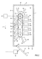
- a conveyor belt 2 is over a first Transport roller 9, which is rotatable about an axis of rotation A1, and a second transport roller 10, which is about an axis of rotation A2 is rotatable, transportable.
- the outer surfaces of the transport rollers 9 and 10 are in contact with the inner surface the conveyor belt closed in the form of an endless belt 2.
- the two transport rollers 9 and 10 are in the direction of gravity G are arranged one above the other so that the conveying path, which the conveyor belt 2 follows, between the two Transport rollers 9 and 10 substantially parallel to Gravity G runs with the two arrows on the Inside of the conveyor belt 2 indicated circulation or Rotation.
- the detergent units 3A to 3D are stacked arranged one above the other and rest on the horizontal, i.e. perpendicular to gravity G, respectively aligned Partitions 5A to 5D.
- the detergent unit is 3E on the other hand just about to slide down because the associated partition 5E on which the detergent unit 3E rests due to the curved movement of the conveyor belt 2 around the transport roller 9 and the reversal of direction moving through more and more the direction of gravity G approaches and thereby the detergent unit 3E if the effective static friction between the Detergent unit 3E and the partition 5E down falls.
- the transport device 1 with the transport rollers 9 and 10, the conveyor belt 2 and the partitions 5A to 5N is complete arranged within a container (or: housing) 6, of which only a rear wall 61, a side wall 60 and a bottom 62 in FIG. 1 and the rear wall 61, the bottom 62, and a blanket 63 are shown in FIG.
- a container or: housing
- a loading opening is provided with a lid or a door 7 can be closed.
- the upper transport roller 10 is on a toothing 11 is provided on one side of the outer surface, the plurality arranged distributed in the circumferential direction Has teeth 12.
- the conveyor belt points accordingly 2 a row of holes 13 with several along the conveyor path holes 14 spaced apart from one another, in each of which a tooth 12 of the toothing 11 engages is feasible.
- the distances of the holes 14 are on the distances (Angular distances) of the teeth 12 of the teeth 11 matched.
- the holes 14 in the conveyor belt 2 according to FIG 1 are Rectangular designed to match the straight toothing designed toothing 11.
- the teeth 12 of the toothing 11 can be designed in particular in the form of involutes his.
- the teeth 11 of the transport roller 10 and the punched tape 13 in the conveyor belt 2 are in the illustrated embodiment arranged on one side, but can also in a central area of the conveyor belt 2 or the transport roller 10 and / or be provided on the other side.
- a plurality of teeth 11 can be axially Axis of rotation A2 offset on the outside of the transport roller 10 can be provided and corresponding parallel to each other running punched tape 13 in the conveyor belt 2 to the transmission select the force more evenly and possibly larger to be able to.
- the conveyor belt 2 is gradually in the direction of rotation moved further by the toothing 11 by the angle ⁇ (only shown in FIG 2) rotated between two teeth 12 becomes. This is about the middle between the partitions 5A to 5N, holes 14 arranged the conveyor belt 2 around Moving the recording tray further, i.e. starting from the one shown Embodiment in FIG 1 and 2 with further movement the conveyor belt 2-step the detergent unit 3A to the position of the detergent unit 3B, the detergent unit 3B in turn the position of the detergent unit 3C and so on.
- the bottom detergent unit 3E now falls to the bottom 62 of the container 6.
- An opening 68 is provided in the bottom 62 of the container 6, which with a flap 8 rotatable about a pivot bearing 28 equipped and lockable.
- the on the flap 8 fallen detergent unit 3E is moved the flap 8 downward, as shown in FIG 2, in the direction one in the interior of the dishwasher or the opening leading to the washing machine.
- the flap 8 is still shown in the closed position, in FIG 2 in the open position.
- the flap 8 via a control device 18, the mechanical is coupled to the flap 8 so as to be rotatable about the rotary bearing 28 adjustable, especially simply between one open position and a closed position.
- That formed with the toothing 11 on the transport roller 10 Gear is together with the entire transport roller 10 via a drive shaft 15 with a not shown Drive motor connected.
- the drive motor can do this within of the container 6 may be arranged or outside of the container 6, in which case the drive shaft 15 through the Housing wall is guided, possibly via a gear.
- the position detection device 20 With the drive shaft 15 and / or the drive motor is now also a position detection device 20 in operative connection or at least metrologically coupled, which in at known the rotational position or angular position the drive shaft 15 and thus the gear 11 are detected, preferably in discrete steps, which is determined by the angular distance formed between two teeth 12 of the teeth 11 Angle ⁇ correspond.
- the position detection device 20 now provides one of the rotational or angular position of the Toothing 11, preferably in multiples of the angle ⁇ , corresponding to a starting position or reference position Position signal P to the control device 18.
- the control device 18 effects after a conveying step by an angle ⁇ , around which the conveyor belt 2 rotates was rotated further, an opening of the flap 8.
- the detergent units 3A to 3E are only on the front the conveyor belt 2 transported and classified the ones on the back Separating elements 5F to 5K no transport or holding functions for detergent units. Since the separators 5F up to 5K normally also stand vertically on the back would also have a corresponding one on the back Space for the transport device 1 can be provided. Now, however, is in household dishwashers or household washing machines the space is usually quite cramped because of the standardized sizes and the multitude of components of these Equipment.
- FIG 1 and FIG 2 each of those on the back Separating elements 5F to 5K folded down towards conveyor belt 2, see above that on the back of the conveyor belt 2 only a smaller one Space is required.
- the Rear wall 61 of the container 6 arranged closer to the conveyor belt 2 than the door 7 in the closed state so that the elastic separators 5F to 5K are bent and attached the rear wall 61 in the conveying direction in the bent state Grind along until they arrive at the top again fold back and essentially perpendicular from the conveyor belt 2 protrude, such as the separator 5L.
- each of the dividers 5A to 5N preferably tapered (or: material savings) 25 provided on which the separating elements Bend 5A to 5N accordingly or deform preferably.
- the taper 25 can in particular with both Provided indentations, recesses or Grooves are formed over the entire width of the separating elements 5A to 5N run.
- Joints or rotating hinges could also be provided be with stop in the conveying direction so that the separating elements 5A to 5N can only be folded down against the conveying direction and would be rotatable around the joints. These hinges are then preferred as well as the tapering arranged closer to the conveyor belt 2 than to the outside Ends of the separators 5A to 5N.
- the Separating elements 5A to 5N also made of a little elastic, rigid material.
- Form the conveyor belt 2 and the separating elements 5A to 5N preferably a coherent molded body which in one single manufacturing process can be produced, for example by injection molding a thermoplastic, especially an elastomer.
- the gearing or the gear 11 preferably also consists of a Plastic with a lower modulus of elasticity than that Conveyor belt 2 or a metal.
- the conveyor belt 2 can also can be driven with two transport rollers without teeth. A hole arrangement 13 in the conveyor belt 2 is then not required.
- the transport rollers generally have a smooth outer surface on.
- a material pairing with one if possible high coefficient of static friction between the material of the Conveyor belt and the material of the transport rollers selected is preferably a material pairing with one if possible high coefficient of static friction between the material of the Conveyor belt and the material of the transport rollers selected, and / or the conveyor belt is made of an elastic. material selected and under a predetermined bias appropriate distance between the two transport rollers set. Due to the restoring force of the elastically deformed Conveyor belt in the normal direction to the outer surfaces of the transport rollers the static friction between the Transport rollers and the conveyor belt increased.
Landscapes
- Engineering & Computer Science (AREA)
- Textile Engineering (AREA)
- Belt Conveyors (AREA)
- Detergent Compositions (AREA)
- Treatment Of Fiber Materials (AREA)
Abstract
Description
wobei die Trennelemente in einem vom ersten Teilbereich verschiedenen zweiten Bereich des Förderweges derart in ihrer Gestalt (oder: Form) anpassbar sind oder angepasst werden, dass sie näher am Förderband liegen oder weniger weit vom Förderband abstehen als im ersten Teilbereich des Förderweges. Mit anderen Worten: der Abstand des am weitesten vom Förderband entfernten Abschnitts oder Bereichs der Trennelemente ist im zweiten Teilbereich des Förderwegs verringert gegenüber dem ersten Teilbereich
- FIG 1
- eine Transportvorrichtung zum Transport mehrerer Reinigungsmittel-Einheiten mittels eines von einem Zahnrad angetriebenen Förderbandes innerhalb eines teilweise geschnittenen Dosierbehälters in einer perspektivischen Ansicht und
- FIG 2
- die Transportvorrichtung gemäß FIG 1 in einer geschnittenen Ansicht mit einer Ansteuerung für eine Ausgabevorrichtung
- 1
- Transportvorrichtung
- 2
- Förderband
- 3A bis 3E
- Reinigungsmittel-Einheiten
- 5A bis 5N
- Trennelement
- 6
- Behälter
- 7
- Tür
- 8
- Klappe
- 9, 10
- Transportwalze
- 11
- Zahnrad
- 12
- Zahn
- 13
- Lochstreifen
- 14
- Loch
- 15
- Antriebswelle
- 18
- Steuereinrichtung
- 20
- Positionserfassungseinrichtung
- 25
- Verjüngung
- 28
- Drehlager
- 60
- Seitenwand
- 61
- Rückwand
- 62
- Boden
- P
- Positionssignal
- α
- Winkel
- A1, A2
- Drehachse
Claims (23)
- Transportvorrichtung (1) zum Transport von Reinigungsmittel-Einheiten (3A bis 3E) für eine Geschirrspülmaschine oder eine Textilwaschmaschine mitwobeia) einem entlang eines Förderweges antreibbaren oder angetriebenen Förderband (2),b) mehreren, vom Förderband nach außen abstehenden Trennelementen (5A bis 5N), zwischen denen wenigstens in einem ersten Teilbereich des Förderweges jeweils wenigstens eine Reinigungsmittel-Einheit anordenbar oder angeordnet ist,c) die Trennelemente in einem vom ersten Teilbereich verschiedenen zweiten Teilbereich des Förderweges derart in ihrer Form veränderbar sind, dass der Abstand des am weitesten außen liegenden Bereichs'der Trehnelemente vom Förderband im zweiten Teilbereich kleiner ist als im ersten Teilbereich.
- Transportvorrichtung nach Anspruch 1, bei der die Trennelemente im zweiten Teilbereich des Förderweges zum Förderband hin abklappbar oder umbiegbar sind oder abgeklappt oder umgebogen werden.
- Transportvorrichtung nach Anspruch 1 oder 2, bei der die Trennelemente wenigstens eine Verjüngung (25) aufweisen und zumindest im Bereich dieser Verjüngung elastisch verformbar sind.
- Transportvorrichtung nach einem oder mehreren der vorhergehenden Ansprüche, bei der die Trennelemente jeweils ein Drehscharnier aufweisen, dessen Drehachse vorzugsweise im Wesentlichen parallel zum Förderband und senkrecht zum Förderweg gerichtet ist.
- Transportvorrichtung nach Anspruch 3 oder Anspruch 4, bei der die Verjüngung oder das Drehscharnier jedes Trennelements näher am Förderband angeordnet ist als am vom Förderband abgewandten Ende des Trennelements.
- Transportvorrichtung nach einem oder mehreren der vorhergehenden Ansprüche, bei der die Trennelemente elastisch verformbar sind oder wenigstens teilweise aus einem elastischen Material bestehen.
- Transportvorrichtung nach einem oder mehreren der vorhergehenden Ansprüche, bei der jedes Trennelement teleskopartig ausziehbar und zusammenschiebbar ist.
- Transportvorrichtung nach einem oder mehreren der vorhergehenden Ansprüche mit einem Behälter (6), in dessen Innenraum das Förderband angeordnet ist und der wenigstens eine Beschickungsöffnung aufweist, durch die der erste Teilbereich des Förderweges zugänglich ist zum Beschicken der Zwischenräume zwischen den Trennelementen mit Reinigungsmittel-Einheiten, wobei vorzugsweise der Behälter (6) einen Verschluss (7) zum Verschließen der Beschickungsöffnung aufweist.
- Transportvorrichtung nach einem oder mehreren der vorhergehenden Ansprüche mit einer dem Förderband im zweiten Teilbereich des Förderweges gegenüberliegenden Gegenwand (61), die näher am Förderband angeordnet ist als die äußersten Bereiche der Trennelemente vom Förderband im ersten Teilbereich des Förderweges beabstandet sind, so dass die Trennelemente an der Gegenwand unter Änderung ihrer Gestalt im Vergleich zu ihrer Gestalt im ersten Teilbereich des Förderweges während der Bewegung im zweiten Teilbereich des Förderweges entlang schleifen.
- Transportvorrichtung nach Anspruch 9 in Rückbeziehung auf Anspruch 8, bei der die Gegenwand mit einer Wand (61) des Behälters (6) gebildet ist.
- Transportvorrichtung nach einem oder mehreren der vorhergehenden Ansprüche, bei der die Trennelemente und das Förderband mit einem zusammenhängenden Formkörper gebildet sind, insbesondere einem Spritzguss-Formkörper.
- Transportvorrichtung nach einem oder mehreren der vorhergehenden Ansprüche, bei der das Förderband auf wenigstens einem und vorzugsweise wenigstens zwei rotierbaren Transportelementen (9, 10) transportierbar öder transportiert ist, wobei vorzugsweise wenigstens ein Transportelement in Form einer Transportwalze (9, 10) ausgebildet ist, deren Außenfläche mit einer Innenfläche des Förderbandes in Kontakt steht.
- Transportvorrichtung nach Anspruch 12, bei der wenigstens ein Transportelement eine Verzahnung, insbesondere ein Zahnrad (11), mit mehreren Zähnen (12) umfasst, und das Förderband eine Lochanordnung (13) mit einer vorgegebenen Anzahl von Löchern (14) entlang des Förderweges aufweist, wobei wenigstens ein Zahn (12) in jeweils ein Loch (14) der Lochanordnung im Förderband eingreift, wobei vorzugsweise wenigstens zwei Zähne der Verzahnung gleichzeitig in jeweils ein Loch der Lochanordnung im Förderband eingreifen.
- Transportvorrichtung nach Anspruch 13, bei der die Lochanordnung im Förderband jeweils wenigstens ein Loch zwischen zwei Trennelementen umfasst und/oder bei der die Löcher (14) der Lochanordnung im Wesentlichen rechteckig ausgestaltet sind und/oder bei der die Löcher (14) der Lochanordnung im Wesentlichen linear, d.h. entlang einer geraden Linie, hintereinander angeordnet sind.
- Transportvorrichtung nach einem oder mehreren der Ansprüche 13 bis 14, bei der die Verzahnung an der AuBenfläche einer Transportwalze (10) für das Förderband gebildet ist.
- Transportvorrichtung nach einem oder mehreren der Ansprüche 12 bis 15, bei der wenigstens zwei Transportelemente eine gemeinsame Rotationsachse oder zueinander parallele Rotationsachsen aufweisen, wobei vorzugsweise wenigstens zwei Transportelemente axial zur Rotationsachse bzw. zu den Rotationsachsen übereinander liegen.
- Transportvorrichtung nach Anspruch 16 in Rückbeziehung auf einen der Ansprüche 13 bis 16, bei der die Verzahnungen der Transportelemente in dieselbe Lochanordnung im Förderband eingreifen.
- Transportvorrichtung nach einem oder mehreren der Ansprüche 13 bis 17, bei der wenigstens zwei Transportelemente mit Verzahnungen oder Zahnrädern axial zur Rotationsachse bzw. zu den Rotationsachsen versetzt zueinander angeordnet sind und das Förderband wenigstens zwei zueinander im Wesentlichen parallel verlaufende Lochanordnungen aufweist, in die jeweils wenigstens eine Verzahnung bzw. ein Zahnrad eingreift.
- Transportvorrichtung nach einem oder mehreren der vorhergehenden Ansprüche, bei der das Förderband (2) entlang eines geschlossenen Förderweges in wenigstens einer Umlaufrichtung antreibbar oder angetrieben ist.
- Transportvorrichtung nach einem oder mehreren der Ansprüche 12 bis 19, bei der die Antriebseinrichtung einen über eine Antriebswelle (15) mit dem wenigstens einen Transportelement gekoppelten oder koppelbaren Antriebsmotor umfasst, wobei vorzugsweise der Antriebsmotor das Förderband in einzelnen Schritten weiterbewegt und dabei vorzugsweise die Schrittlänge durch den Abstand oder die Abstände der Trennelemente bestimmt ist.
- Transportvorrichtung nach einem oder mehreren der vorhergehenden Ansprüche, bei der im zweiten Teilbereich des Förderweges eine Engstelle angeordnet ist, in der die Trennelemente in Richtung auf das Förderband zu verformt oder in ihrer Gestalt verändert werden.
- Transportvorrichtung nach einem oder mehreren der vorhergehenden Ansprüche, bei der jede zwischen zwei Trennelementen angeordnete Reinigungsmittel-Einheit an wenigstens einer vorgegebenen Ausgabeposition ausgebbar oder entnehmbar ist oder aufgrund der Schwerkraft herausfällt, und der erste Teilbereich und der zweite Teilbereich des Förderweges an verschiedenen Seiten der Ausgabeposition liegen.
- Dosiervorrichtung zum Dosieren von Reinigungsmittel-Einheiten für eine Geschirrspülmaschine oder eine Textilwaschmaschine mitwobeia) einer Ausgabevorrichtung (8, 18) zum Ausgeben von Reinigungsmittel-Einheiten,b) einer Transportvorrichtung nach einem oder mehreren der vorhergehenden Ansprüche zum Transport von Reinigungsmittel-Einheiten zu der Ausgabevorrichtung,c) die Ausgabevorrichtung mit der Ausgabeposition der Transportvorrichtung verbunden oder gekoppelt ist.
Applications Claiming Priority (2)
| Application Number | Priority Date | Filing Date | Title |
|---|---|---|---|
| DE10127180 | 2001-06-05 | ||
| DE10127180A DE10127180A1 (de) | 2001-06-05 | 2001-06-05 | Transportvorrichtung zum Transport von Reinigungsmittel-Einheiten für eine Geschirrspülmaschine oder eine Textilwaschmaschine |
Publications (2)
| Publication Number | Publication Date |
|---|---|
| EP1264927A2 true EP1264927A2 (de) | 2002-12-11 |
| EP1264927A3 EP1264927A3 (de) | 2004-02-11 |
Family
ID=7687197
Family Applications (1)
| Application Number | Title | Priority Date | Filing Date |
|---|---|---|---|
| EP02010283A Withdrawn EP1264927A3 (de) | 2001-06-05 | 2002-05-21 | Transportvorrichtung zum Transport von Reinigungmittel-Einheiten für eine Geschirrspülmaschine oder eine Textilwaschmaschine |
Country Status (2)
| Country | Link |
|---|---|
| EP (1) | EP1264927A3 (de) |
| DE (1) | DE10127180A1 (de) |
Family Cites Families (3)
| Publication number | Priority date | Publication date | Assignee | Title |
|---|---|---|---|---|
| GB8703368D0 (en) * | 1987-02-13 | 1987-03-18 | Currys Group Plc | Loading apparatus |
| DE19636417A1 (de) * | 1996-09-07 | 1998-03-12 | Aeg Hausgeraete Gmbh | Geschirrspülmaschine mit einer Dosiervorrichtung |
| DE10127177A1 (de) * | 2001-06-05 | 2002-12-12 | Aeg Hausgeraete Gmbh | Transportvorrichtung zum Transport von Reinigungsmittel-Einheiten für eine Geschirrspülmaschine oder eine Textilwaschmaschine |
-
2001
- 2001-06-05 DE DE10127180A patent/DE10127180A1/de not_active Withdrawn
-
2002
- 2002-05-21 EP EP02010283A patent/EP1264927A3/de not_active Withdrawn
Also Published As
| Publication number | Publication date |
|---|---|
| EP1264927A3 (de) | 2004-02-11 |
| DE10127180A1 (de) | 2002-12-12 |
Similar Documents
| Publication | Publication Date | Title |
|---|---|---|
| DE102013008973B4 (de) | Vorrichtung zum Fördern von Fluiden | |
| DE4204483C2 (de) | Entwicklungsvorrichtung für eine Bilderzeugungseinrichtung | |
| DE112011103935T5 (de) | Werkzeug zum Sammeln und Lenken von Schmieröl | |
| EP2990530B1 (de) | Baumaschine mit versetzten bunkerrückwänden | |
| DE3806723C2 (de) | Zwischenkasse für Selbstverkäufer | |
| DE102013022329A1 (de) | Vorrichtung zum Fördern von Fluiden | |
| DE2341535A1 (de) | Foerderer fuer pappschachteln | |
| DE19603464A1 (de) | Vorrichtung zum Beladen von Aufnahmebehältern für langgestreckte Gegenstände | |
| DE202004002601U1 (de) | Vorrichtung zum Dosieren von Schüttgütern mit einem Rührwerk und einer Antriebseinheit | |
| DE3842273A1 (de) | Vorrichtung zum fuellen von vertiefungen in blisterpackungen | |
| DE60128394T2 (de) | Münzzuführungsvorrichtung | |
| EP1264571A1 (de) | Transportvorrichtung zum Transport von Reinigungsmittel-Einheiten für eine Geschirrspülmaschine oder eine Textilwaschmaschine | |
| EP1264926A2 (de) | Dosiervorrichtung zum Dosieren von Reinigungsmittel-Einheiten für eine Geschirrspülmaschine oder eine Textilwaschmaschine | |
| DE10127180A1 (de) | Transportvorrichtung zum Transport von Reinigungsmittel-Einheiten für eine Geschirrspülmaschine oder eine Textilwaschmaschine | |
| DE102004012825B4 (de) | Ausgabeeinheit für Waren, insbesondere Backwaren | |
| DE102022001668A1 (de) | Mischvorrichtung für Lebensmittelprodukte | |
| DE3144305C2 (de) | Vorrichtung zum Mischen von körnigem oder pulverförmigem Material | |
| DE69306873T2 (de) | Blattausrichtvorrichtung in einem Blattsortiergerät | |
| WO2021018612A1 (de) | Haushalts-geschirrspülmaschine | |
| DE112017000395T5 (de) | Kühlschrank | |
| DE102010028214A1 (de) | Stellmechanismus für den Einsatz in berührungslosen Stapelsystemen | |
| DE102011054581A1 (de) | Vorrichtung und Verfahren zur Bereitstellung von Auswuchtgewichten | |
| DE102011054579A1 (de) | Kassette zur Aufnahme von Auswuchtgewichten und Vorrichtung zur Bereitstellung von Auswuchtgewichten | |
| DE102006012029B4 (de) | Overhead-Warenausgabebehälter | |
| DE2611738C3 (de) | Vorrichtung zum dosierten Abgeben von körnigem bis pulverförmigem fließfähigen Gut |
Legal Events
| Date | Code | Title | Description |
|---|---|---|---|
| PUAI | Public reference made under article 153(3) epc to a published international application that has entered the european phase |
Free format text: ORIGINAL CODE: 0009012 |
|
| AK | Designated contracting states |
Kind code of ref document: A2 Designated state(s): AT BE CH CY DE DK ES FI FR GB GR IE IT LI LU MC NL PT SE TR |
|
| AX | Request for extension of the european patent |
Free format text: AL;LT;LV;MK;RO;SI |
|
| PUAL | Search report despatched |
Free format text: ORIGINAL CODE: 0009013 |
|
| AK | Designated contracting states |
Kind code of ref document: A3 Designated state(s): AT BE CH CY DE DK ES FI FR GB GR IE IT LI LU MC NL PT SE TR |
|
| AX | Request for extension of the european patent |
Extension state: AL LT LV MK RO SI |
|
| AKX | Designation fees paid | ||
| REG | Reference to a national code |
Ref country code: DE Ref legal event code: 8566 |
|
| STAA | Information on the status of an ep patent application or granted ep patent |
Free format text: STATUS: THE APPLICATION IS DEEMED TO BE WITHDRAWN |
|
| 18D | Application deemed to be withdrawn |
Effective date: 20040812 |