EP1264732B1 - Lighting arrangement for the illumination of the number plate of motor-vehicles - Google Patents
Lighting arrangement for the illumination of the number plate of motor-vehicles Download PDFInfo
- Publication number
- EP1264732B1 EP1264732B1 EP02011153A EP02011153A EP1264732B1 EP 1264732 B1 EP1264732 B1 EP 1264732B1 EP 02011153 A EP02011153 A EP 02011153A EP 02011153 A EP02011153 A EP 02011153A EP 1264732 B1 EP1264732 B1 EP 1264732B1
- Authority
- EP
- European Patent Office
- Prior art keywords
- number plate
- leds
- illumination
- lens
- motor
- Prior art date
- Legal status (The legal status is an assumption and is not a legal conclusion. Google has not performed a legal analysis and makes no representation as to the accuracy of the status listed.)
- Expired - Lifetime
Links
- 238000005286 illumination Methods 0.000 title claims description 16
- 238000009304 pastoral farming Methods 0.000 claims description 3
- 230000000694 effects Effects 0.000 description 3
- 239000011521 glass Substances 0.000 description 3
- 239000000463 material Substances 0.000 description 3
- 230000003287 optical effect Effects 0.000 description 2
- 230000007797 corrosion Effects 0.000 description 1
- 238000005260 corrosion Methods 0.000 description 1
- 230000001419 dependent effect Effects 0.000 description 1
- 238000005516 engineering process Methods 0.000 description 1
- 230000007257 malfunction Effects 0.000 description 1
- 239000002184 metal Substances 0.000 description 1
- 230000004048 modification Effects 0.000 description 1
- 238000012986 modification Methods 0.000 description 1
- 230000003647 oxidation Effects 0.000 description 1
- 238000007254 oxidation reaction Methods 0.000 description 1
- 230000000149 penetrating effect Effects 0.000 description 1
- 239000004033 plastic Substances 0.000 description 1
- 229920003023 plastic Polymers 0.000 description 1
- 229920003229 poly(methyl methacrylate) Polymers 0.000 description 1
- 239000004926 polymethyl methacrylate Substances 0.000 description 1
- 239000011241 protective layer Substances 0.000 description 1
Images


Classifications
-
- B—PERFORMING OPERATIONS; TRANSPORTING
- B60—VEHICLES IN GENERAL
- B60Q—ARRANGEMENT OF SIGNALLING OR LIGHTING DEVICES, THE MOUNTING OR SUPPORTING THEREOF OR CIRCUITS THEREFOR, FOR VEHICLES IN GENERAL
- B60Q1/00—Arrangement of optical signalling or lighting devices, the mounting or supporting thereof or circuits therefor
- B60Q1/26—Arrangement of optical signalling or lighting devices, the mounting or supporting thereof or circuits therefor the devices being primarily intended to indicate the vehicle, or parts thereof, or to give signals, to other traffic
- B60Q1/56—Arrangement of optical signalling or lighting devices, the mounting or supporting thereof or circuits therefor the devices being primarily intended to indicate the vehicle, or parts thereof, or to give signals, to other traffic for illuminating registrations or the like, e.g. for licence plates
Definitions
- the present invention refers to a lighting arrangement adapted to illuminate the number plate of motor-vehicles, in particular motor-cars.
- the number plate provided in the rear of motor-cars is usually capable of being illuminated by means of incandescent lamps, which are mounted on at least a support member attached to the body of the vehicle.
- the lamps need to be protected by means of glass coverings, or the like, mounted on the support member. Furthermore, the electrical connections of the same lamps and the above mentioned boot unlocking device are implemented with the use of wirings, or metal strips, as this is described for instance in EP-A-0 976 617 .
- US-A-5,934,798 discloses a generic lighting arrangement for the illumination of the number plate of motor vehicles comprising LEDs, illuminating said number plate through at least a focusing lens.
- the specific optics which is necessary to control the light distribution in order to satisfy the applicable industry standards.
- the light signals must not disturb external observers and must illuminate the number plate in an uniform way, taking into consideration that the light intensity is inversely proportional to the square of the distance from the light source.
- the assembly of the whole support member turns out to be undesirably laborious, i.e. demanding, and expensive on an industrial scale.
- said support member is scarcely reliable owing to the moisture that, by quite easily penetrating thereinto in correspondence of the glass coverings used as a protection for the lamps, causes the electrical contacts to undergo corrosion/oxidation problems and this obviously gives rise to conditions of malfunction. This phenomenon is even made worse by the combination of such a moisture with the heat generated by the incandescent lamps.
- the number plate which is usually situated below the illumination arrangement, has a widened rectangular shape and a surface that extends on a plane upon which the light emitted by said LEDs falls in an almost grazing manner, turns on the whole out as being illuminated in a quite uneven, unsatisfactory manner.
- the number plate turns undesirably out to be illuminated with a "spot-like pattern", in which the various spots have a differing and/or insufficient intensity.
- it is a purpose of the present invention is to provide a lighting arrangement of the above cited kind, which has a particularly simple and reliable structure, is particular compact, while at the same time ensuring an optimum and agreeable illumination of the number plate.
- a further purpose yet of the present invention is to provide a lighting arrangement for the illumination of the number plate of motor-vehicles, which is particularly low-cost and convenient to assemble.
- the lighting arrangement according to the present invention is adapted to be mounted on a support 1, which may be formed directly 30 by the body 8 of a motor-vehicle, or else be constituted by an appropriately shaped member (as shown in Figures 1 and 4) that is in turn adapted to be attached to the body of the vehicle.
- a support 1 may be formed directly 30 by the body 8 of a motor-vehicle, or else be constituted by an appropriately shaped member (as shown in Figures 1 and 4) that is in turn adapted to be attached to the body of the vehicle.
- the actual support arrangement 1 is located in a position that is adjacent to an edge of the number plate 2, which in the herein described example corresponds to the upper major side of the same number plate.
- the lighting arrangement mainly comprises one or more LEDs distributed according to a suitable side-by-side arrangement, appropriately spaced from each other, along a direction that is substantially parallel to the plane defined by the number plate 2 of the motor-vehicle.
- These LEDs are preferably of the high-intensity white-light type and may for instance be made according to the SMD technology.
- the LEDs 3 are preferably attached to a support and connection board 4 of the printed-circuit board type, or the like, which is in turn mounted in a corresponding receptacle 9 provided in the support member 1.
- the LEDs 3, each one of which is adapted to emit a beam of light in the shape of a pre-determined cone, are oriented and arranged in such a manner as to be able to illuminate the number plate 2 through at least a focusing lens 5, which may for instance be made of a suitable plastic material (eg. PMMA or PC) or a glass material, wherein such a material shall in any case be substantially transparent to visible light.
- said focusing lens 5 is adapted to substantially collimate (i.e. reduce the natural convergence of) the light emitted by the LEDs themselves in a transversal direction (as illustrated in Figure 1) and diffuse the same light (ie. maintain the natural divergence thereof) in a longitudinal direction (as illustrated in Figure 3).
- the focusing lens 5 is shaped to show a substantially elongated semi-cylindrical (or similar) configuration with the axis thereof extending in a direction that is substantially parallel to the plane of the number plate 2.
- the lens 5 is so shaped as to feature a preferably planar receiving surface 6 facing the LEDs 3 and adjacent thereto.
- the lens 5 features a substantially curvilinear and convex (eg. spherical-cylindrical or semicircular) emitting surface 7 opposing the surface 6.
- a substantially curvilinear and convex eg. spherical-cylindrical or semicircular
- the emitting surface 7 of the lens is oriented directly towards the number plate 2, i.e. in a direction that is very inclined (almost grazing, as this can be best noticed in Figure 1) with respect to the same number plate, in such a manner as to allow for the use of a support member 1 that protrudes from the body 8 of the motor-vehicle, with respect to the number plate 2, by an advantageously reduced length that substantially does not put any limitation to the structural and application-related versatility thereof.
- the focusing lens 5 directs towards the number plate 2 a light beam (schematically indicated at 10) which is formed by the light emitted by all of the LEDs 3 that are associated to the same lens.
- this light beam 10 is diffused longitudinally so as to substantially fall upon the whole width of the number plate 2, as illustrated in Figure 3.
- the light beam 10 is substantially collimated in the transverse direction so as to fall upon the whole height of the number plate 2, as illustrated in Figure 1.
- the LEDs 3 are preferably arranged at a distance q from the vertex of the curvilinear surface 7 of the focusing lens 5 that is substantially equal to or slightly shorter than the focal length f of the same lens. A perfect collimation is obtained in this way, while the light is emitted from the lens 5 as a beam of substantially parallel or just slightly diverging rays, respectively.
- the LEDs 3 are arranged closer to the lens 5 with respect to the position of the focus of the same lens, so as to allow for the light to diverge by the desired angle.
- the arrangement comprising the LEDs 3 and the associated focusing lens 5 emits a "shaped" light beam 10 (with a substantially elliptical cross-section) that illuminates the number plate 2 in a substantially complete, uniform manner, with an adequate light intensity and an agreeable aesthetical effect.
- said reflecting surface 11 is arranged inside the same seat or receptacle 9 accommodating the LEDs 3, in a position that is adjacent to the extremity 12 of the support member 1 which is most protruding with respect to the number plate 2. It is therefore possible, through the use of extremely simple, reliable, low-cost and scarcely space-demanding means, for the angle of incidence of the light beam 10 upon the number plate 2 to be sensibly increased (by as much as this is allowed for by the form and the dimensions of the support member 1), so that the same number plate turns actually out to be illuminated in a still more effective manner.
- the reflecting surface 11 enables the length of the optical path to be increased and, with it, the overlapping effect of the light beams emitted by the various LEDs to be advantageously enhanced.
- a same number plate 2 may be illuminated through more focusing lenses 5 provided in a side-by-side arrangement and/or each focusing lens 5 may also be associated to a single LED 3, as already mentioned earlier in this description.
Landscapes
- Engineering & Computer Science (AREA)
- Mechanical Engineering (AREA)
- Non-Portable Lighting Devices Or Systems Thereof (AREA)
- Lighting Device Outwards From Vehicle And Optical Signal (AREA)
- Traffic Control Systems (AREA)
- Led Device Packages (AREA)
- Arrangements Of Lighting Devices For Vehicle Interiors, Mounting And Supporting Thereof, Circuits Therefore (AREA)
- Laminated Bodies (AREA)
- Securing Globes, Refractors, Reflectors Or The Like (AREA)
Abstract
Description
- The present invention refers to a lighting arrangement adapted to illuminate the number plate of motor-vehicles, in particular motor-cars.
- As generally known, the number plate provided in the rear of motor-cars is usually capable of being illuminated by means of incandescent lamps, which are mounted on at least a support member attached to the body of the vehicle.
- In particular, generally known in the art is the practice based on the use of an elongated support body which is attached to the rear boot of the vehicle, and which, further to the lamps for the illumination of the number plate, may for example also support a manually actuatable electro-mechanical device for opening said boot. In other words, a manually actuatable lever is provided there to operate a switch, which in turn is adapted to energize an electric motor, or the like, to release the lock fastening said boot.
- In the above cited prior-art solutions, the lamps need to be protected by means of glass coverings, or the like, mounted on the support member. Furthermore, the electrical connections of the same lamps and the above mentioned boot unlocking device are implemented with the use of wirings, or metal strips, as this is described for instance in
EP-A-0 976 617 . -
US-A-5,934,798 discloses a generic lighting arrangement for the illumination of the number plate of motor vehicles comprising LEDs, illuminating said number plate through at least a focusing lens. However, no teaching is supplied concerning the specific optics which is necessary to control the light distribution in order to satisfy the applicable industry standards. In fact, the light signals must not disturb external observers and must illuminate the number plate in an uniform way, taking into consideration that the light intensity is inversely proportional to the square of the distance from the light source. - In any case, the assembly of the whole support member turns out to be undesirably laborious, i.e. demanding, and expensive on an industrial scale.
- Furthermore, said support member is scarcely reliable owing to the moisture that, by quite easily penetrating thereinto in correspondence of the glass coverings used as a protection for the lamps, causes the electrical contacts to undergo corrosion/oxidation problems and this obviously gives rise to conditions of malfunction. This phenomenon is even made worse by the combination of such a moisture with the heat generated by the incandescent lamps.
- In addition, it should be considered that the bulkiness of the support member sets substantial limitations to the structural and application-related versatility thereof.
- In view of substantially minimizing all such drawbacks, it has been proposed to replace the traditional incandescent lamps with an array of high-luminosity LEDs provided in a side-by-side arrangement and embedded in a sealed sandwich-like structure having a transparent protective layer through which the LEDs illuminate the number plate.
- Such a solution, however, turned out to be scarcely satisfactory, owing to the fact that the number plate, which is usually situated below the illumination arrangement, has a widened rectangular shape and a surface that extends on a plane upon which the light emitted by said LEDs falls in an almost grazing manner, turns on the whole out as being illuminated in a quite uneven, unsatisfactory manner. In practice, it can be stated that the number plate turns undesirably out to be illuminated with a "spot-like pattern", in which the various spots have a differing and/or insufficient intensity.
- It therefore is a main purpose of the present invention to provide a lighting arrangement for the illumination of the number plate of motor-vehicles, which is effective in minimizing the drawbacks connected with the above cited prior-art solutions.
- More particularly, it is a purpose of the present invention is to provide a lighting arrangement of the above cited kind, which has a particularly simple and reliable structure, is particular compact, while at the same time ensuring an optimum and agreeable illumination of the number plate.
- A further purpose yet of the present invention is to provide a lighting arrangement for the illumination of the number plate of motor-vehicles, which is particularly low-cost and convenient to assemble.
- According to the present invention, this object is achieved in a lighting arrangement defined in the independent claim. Embodiments of the invention are disclosed in the dependent claims.
- Anyway, features and advantages of the present invention will be more readily understood from the description that is given below by way of non-limiting example with reference to the accompanying drawings, in which:
- Figure 1 is a schematic cross-sectional view of a first embodiment of the lighting arrangement according to the present invention;
- Figure 2 is a perspective exploded view of the main optical component parts of the lighting arrangement of Figure 1;
- Figure 3 is a schematic front view of the lighting arrangement of Figure 1 and the number plate associated thereto; and
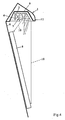
- Figure 4 is a schematic cross-sectional view of a different embodiment of the lighting arrangement according to the present invention.
- With particular reference to Figures 1 and 2, the lighting arrangement according to the present invention is adapted to be mounted on a support 1, which may be formed directly 30 by the
body 8 of a motor-vehicle, or else be constituted by an appropriately shaped member (as shown in Figures 1 and 4) that is in turn adapted to be attached to the body of the vehicle. In any case, the actual support arrangement 1 is located in a position that is adjacent to an edge of thenumber plate 2, which in the herein described example corresponds to the upper major side of the same number plate. - The lighting arrangement mainly comprises one or more LEDs distributed according to a suitable side-by-side arrangement, appropriately spaced from each other, along a direction that is substantially parallel to the plane defined by the
number plate 2 of the motor-vehicle. These LEDs (three of which are shown by way of example in Figures 2 and 3, where they are generally indicated at 3) are preferably of the high-intensity white-light type and may for instance be made according to the SMD technology. - Furthermore, the
LEDs 3 are preferably attached to a support andconnection board 4 of the printed-circuit board type, or the like, which is in turn mounted in a corresponding receptacle 9 provided in the support member 1. - The
LEDs 3, each one of which is adapted to emit a beam of light in the shape of a pre-determined cone, are oriented and arranged in such a manner as to be able to illuminate thenumber plate 2 through at least a focusinglens 5, which may for instance be made of a suitable plastic material (eg. PMMA or PC) or a glass material, wherein such a material shall in any case be substantially transparent to visible light. - According to a feature of the present invention, with respect to the direction of alignment of the
LEDs 3, said focusinglens 5 is adapted to substantially collimate (i.e. reduce the natural convergence of) the light emitted by the LEDs themselves in a transversal direction (as illustrated in Figure 1) and diffuse the same light (ie. maintain the natural divergence thereof) in a longitudinal direction (as illustrated in Figure 3). - To such a purpose, the focusing
lens 5 is shaped to show a substantially elongated semi-cylindrical (or similar) configuration with the axis thereof extending in a direction that is substantially parallel to the plane of thenumber plate 2. - As illustrated in Figure 2, in particular, the
lens 5 is so shaped as to feature a preferably planar receiving surface 6 facing theLEDs 3 and adjacent thereto. - Furthermore, the
lens 5 features a substantially curvilinear and convex (eg. spherical-cylindrical or semicircular) emitting surface 7 opposing the surface 6. - In the herein described example, the emitting surface 7 of the lens is oriented directly towards the
number plate 2, i.e. in a direction that is very inclined (almost grazing, as this can be best noticed in Figure 1) with respect to the same number plate, in such a manner as to allow for the use of a support member 1 that protrudes from thebody 8 of the motor-vehicle, with respect to thenumber plate 2, by an advantageously reduced length that substantially does not put any limitation to the structural and application-related versatility thereof. - In any case, the focusing
lens 5 directs towards the number plate 2 a light beam (schematically indicated at 10) which is formed by the light emitted by all of theLEDs 3 that are associated to the same lens. - In particular, this
light beam 10 is diffused longitudinally so as to substantially fall upon the whole width of thenumber plate 2, as illustrated in Figure 3. - Furthermore, the
light beam 10 is substantially collimated in the transverse direction so as to fall upon the whole height of thenumber plate 2, as illustrated in Figure 1. - Considering the relation governing the conjugate points or foci of a lens, the
LEDs 3 are preferably arranged at a distance q from the vertex of the curvilinear surface 7 of the focusinglens 5 that is substantially equal to or slightly shorter than the focal length f of the same lens. A perfect collimation is obtained in this way, while the light is emitted from thelens 5 as a beam of substantially parallel or just slightly diverging rays, respectively. - In other words, to the purpose of obtaining a regular and diffuse illumination effect it is preferable for the
LEDs 3 to be arranged closer to thelens 5 with respect to the position of the focus of the same lens, so as to allow for the light to diverge by the desired angle. - In conclusion, the arrangement comprising the
LEDs 3 and the associated focusinglens 5 emits a "shaped" light beam 10 (with a substantially elliptical cross-section) that illuminates thenumber plate 2 in a substantially complete, uniform manner, with an adequate light intensity and an agreeable aesthetical effect. - It will of course be appreciated that the illumination of the
number plate 2 improves with an increasing angle of incidence of thelight beam 10. However, as this has been said earlier in this description, such an angle of incidence is limited by the necessarily reduced depth of the support member 1. - Even this drawback can anyway be minimized by an embodiment according to the variant illustrated in Figure 4, in which the focusing
lens 5 is so oriented as to be able to emit thelight beam 10 in a direction that is substantially orthogonal to the plane of thenumber plate 2, and such a light beam is reflected towards the number plate by at least a reflectingsurface 11, which may be planar, parabolic or variously shaped according to the needs. - Preferably, said reflecting
surface 11 is arranged inside the same seat or receptacle 9 accommodating theLEDs 3, in a position that is adjacent to theextremity 12 of the support member 1 which is most protruding with respect to thenumber plate 2. It is therefore possible, through the use of extremely simple, reliable, low-cost and scarcely space-demanding means, for the angle of incidence of thelight beam 10 upon thenumber plate 2 to be sensibly increased (by as much as this is allowed for by the form and the dimensions of the support member 1), so that the same number plate turns actually out to be illuminated in a still more effective manner. - In addition, the reflecting
surface 11 enables the length of the optical path to be increased and, with it, the overlapping effect of the light beams emitted by the various LEDs to be advantageously enhanced. - It will be appreciated that the above described lighting arrangement may be the subject of a number of modifications without departing from the scope of the present invention as defined in the appended claims.
- For instance, a
same number plate 2 may be illuminated through more focusinglenses 5 provided in a side-by-side arrangement and/or each focusinglens 5 may also be associated to asingle LED 3, as already mentioned earlier in this description.
Claims (7)
- Lighting arrangement for the illumination of the number plate of motor-vehicles, comprising one or more LEDs that are adapted to emit each a pre-determined respective conical beam of light and are provided in a side-by-side arrangement along a direction that is substantially parallel to the plane defined by said number plate, said LEDs (3) are adapted to illuminate said number plate (2) through at least a focusing lens (5),
characterized in that
said lens (5) is so shaped as to feature a substantially elongated semi-cylindrical conformation with the axis thereof extending in a direction that is substantially parallel to the plane of the number plate (2), in which said lens (5) has a planar receiving surface (6) facing said LEDs (3) and a convex emitting surface (7) opposed to said receiving surface, and, with respect to the direction of alignment of the LEDs (3), is adapted to substantially limit the divergence of the light emitted by the same LEDs in the transverse direction, while on the contrary favouring the natural divergence of the same light in the longitudinal direction. - Lighting arrangement for the illumination of the number plate of motor-vehicles according to claim 1, characterized in that said LEDs (3) are situated at a distance (q) from the vertex of said convex surface (7) of the lens (5), in which said distance is substantially equal to or slightly shorter than the focal length (f) of the same lens.
- Lighting arrangement for the illumination of the number plate of motor-vehicles according to claim 1, characterized in that said LEDs (3) are attached to a support and connection board (4) of the printed-circuit board type or the like.
- Lighting arrangement for the illumination of the number plate of motor-vehicles according to claim 1, characterized in that said LEDs (3) and said lens (5) are mounted in a receptacle (9) provided in a support member (1) adjacent to said number plate (2) and protruding with respect thereto.
- Lighting arrangement for the illumination of the number plate of motor-vehicles according to claim 4, characterized in that said planar emitting surface (6) of the lens (5) is oriented directly towards the number plate (2) in a substantially grazing direction.
- Lighting arrangement for the illumination of the number plate of motor-vehicles according to claim 4, characterized in that said light beam (10) emitted by the lens (5) is reflected towards the number plate (2) by at least a reflecting surface (11).
- Lighting arrangement for the illumination of the number plate of motor-vehicles according to claim 6, characterized in that said reflecting surface (11) is provided in correspondence of an extremity (12) of said support member (1) protruding with respect to the number plate (2).
Applications Claiming Priority (2)
| Application Number | Priority Date | Filing Date | Title |
|---|---|---|---|
| ITPN20010040 | 2001-06-08 | ||
| IT2001PN000040A ITPN20010040A1 (en) | 2001-06-08 | 2001-06-08 | VEHICLE PLATE LIGHTING DEVICE |
Publications (3)
| Publication Number | Publication Date |
|---|---|
| EP1264732A2 EP1264732A2 (en) | 2002-12-11 |
| EP1264732A3 EP1264732A3 (en) | 2006-01-18 |
| EP1264732B1 true EP1264732B1 (en) | 2007-07-04 |
Family
ID=11453277
Family Applications (1)
| Application Number | Title | Priority Date | Filing Date |
|---|---|---|---|
| EP02011153A Expired - Lifetime EP1264732B1 (en) | 2001-06-08 | 2002-05-21 | Lighting arrangement for the illumination of the number plate of motor-vehicles |
Country Status (4)
| Country | Link |
|---|---|
| EP (1) | EP1264732B1 (en) |
| AT (1) | ATE366205T1 (en) |
| DE (1) | DE60220971T2 (en) |
| IT (1) | ITPN20010040A1 (en) |
Families Citing this family (8)
| Publication number | Priority date | Publication date | Assignee | Title |
|---|---|---|---|---|
| US7163322B2 (en) * | 2003-09-19 | 2007-01-16 | Toyoda Gosei Co., Ltd. | Illumination device for license plate |
| DE102006018259B4 (en) * | 2006-04-20 | 2017-10-05 | Volkswagen Ag | Illuminated license plate holder for a vehicle |
| ES2303453B2 (en) * | 2006-11-10 | 2009-03-01 | Maier, S. Coop. | LIGHTING SYSTEM OF THE VEHICLE REGISTRATION PLATE. |
| ITPN20070022A1 (en) | 2007-04-17 | 2008-10-18 | Plastal Spa | "DEVICE FOR ILLUMINATING A CAR LICENSE PLATE" |
| JP5503109B2 (en) * | 2008-02-06 | 2014-05-28 | 株式会社小糸製作所 | License plate lamp |
| JP6766789B2 (en) * | 2017-09-26 | 2020-10-14 | 豊田合成株式会社 | Backdoor handle device |
| DE102018209010A1 (en) * | 2018-06-07 | 2019-12-12 | Osram Gmbh | VEHICLE WITH AN ILLUMINATOR AND A METHOD |
| JP2021113882A (en) * | 2020-01-17 | 2021-08-05 | 株式会社東海理化電機製作所 | Lens and license lamp |
Family Cites Families (7)
| Publication number | Priority date | Publication date | Assignee | Title |
|---|---|---|---|---|
| US4733335A (en) * | 1984-12-28 | 1988-03-22 | Koito Manufacturing Co., Ltd. | Vehicular lamp |
| US4857890A (en) * | 1988-03-02 | 1989-08-15 | Wolo Manufacturing Co. | Safety rear license plate frame |
| FR2729457A1 (en) * | 1995-01-12 | 1996-07-19 | Peugeot | Illumination by light reflection of a vehicles registration plate |
| US5934798A (en) * | 1997-03-07 | 1999-08-10 | Truck-Lite Co., Inc. | Light emitting diode license lamp |
| FR2777239A1 (en) * | 1998-04-14 | 1999-10-15 | Stea Sarl | REMOVABLE RADIO LINK ROAD PLATE |
| US6027235A (en) * | 1998-07-23 | 2000-02-22 | Chen; Yu-Liang | Number plate housing |
| IT245321Y1 (en) | 1998-07-27 | 2002-03-20 | Plastal Zcp Spa | SUPPORT BODY FOR TARGADI VEHICLE LIGHTING LAMPS |
-
2001
- 2001-06-08 IT IT2001PN000040A patent/ITPN20010040A1/en unknown
-
2002
- 2002-05-21 AT AT02011153T patent/ATE366205T1/en not_active IP Right Cessation
- 2002-05-21 EP EP02011153A patent/EP1264732B1/en not_active Expired - Lifetime
- 2002-05-21 DE DE60220971T patent/DE60220971T2/en not_active Expired - Lifetime
Also Published As
| Publication number | Publication date |
|---|---|
| ATE366205T1 (en) | 2007-07-15 |
| DE60220971T2 (en) | 2008-03-06 |
| EP1264732A2 (en) | 2002-12-11 |
| EP1264732A3 (en) | 2006-01-18 |
| DE60220971D1 (en) | 2007-08-16 |
| ITPN20010040A1 (en) | 2002-12-08 |
Similar Documents
| Publication | Publication Date | Title |
|---|---|---|
| EP2071228B1 (en) | Vehicle lamp assembly | |
| US6367957B1 (en) | Lighting, especially for motor vehicles | |
| JP4930787B2 (en) | VEHICLE LIGHT AND LIGHT GUIDE LENS USED FOR VEHICLE LIGHT | |
| KR101268814B1 (en) | Turn-indicator light module for a vehicle mirror assembly and a vehicle mirror assembly comprising turn-indicator light module | |
| US6814475B2 (en) | Led-type vehicular lamp having uniform brightness | |
| EP1058226B1 (en) | Display lamp | |
| US20020057575A1 (en) | Side flashing lamp | |
| CN114787557B (en) | Vehicle lights | |
| KR20030015865A (en) | Vehicle lamp | |
| JP4735852B2 (en) | Vehicle headlamp | |
| JP2006236588A (en) | Light illumination device and vehicular lamp | |
| KR20170097674A (en) | Lighting device for vehicles | |
| JP6609135B2 (en) | Rear combination lamp for vehicles | |
| KR20160123286A (en) | Lighting and/or signalling system with light guides for a vehicle | |
| US10612743B2 (en) | Vehicle lamp | |
| CZ2012562A3 (en) | Feeding device for geometrically enclosed waveguide | |
| JP7336375B2 (en) | vehicle lamp | |
| EP1264732A2 (en) | Lighting arrangement for the illumination of the number plate of motor-vehicles | |
| JP7557337B2 (en) | Vehicle lighting fixtures | |
| JP7246197B2 (en) | vehicle lamp | |
| JP2022053395A (en) | Vehicular lighting fixture | |
| JP7336376B2 (en) | vehicle lamp | |
| JP7629800B2 (en) | Vehicle lighting fixtures | |
| JP2019139934A (en) | Lighting appliance for vehicle | |
| CN115195579A (en) | Car light structure |
Legal Events
| Date | Code | Title | Description |
|---|---|---|---|
| PUAI | Public reference made under article 153(3) epc to a published international application that has entered the european phase |
Free format text: ORIGINAL CODE: 0009012 |
|
| AK | Designated contracting states |
Kind code of ref document: A2 Designated state(s): AT BE CH CY DE DK ES FI FR GB GR IE IT LI LU MC NL PT SE TR |
|
| AX | Request for extension of the european patent |
Free format text: AL;LT;LV;MK;RO;SI |
|
| PUAL | Search report despatched |
Free format text: ORIGINAL CODE: 0009013 |
|
| AK | Designated contracting states |
Kind code of ref document: A3 Designated state(s): AT BE CH CY DE DK ES FI FR GB GR IE IT LI LU MC NL PT SE TR |
|
| AX | Request for extension of the european patent |
Extension state: AL LT LV MK RO SI |
|
| 17P | Request for examination filed |
Effective date: 20060419 |
|
| AKX | Designation fees paid |
Designated state(s): AT BE CH CY DE DK ES FI FR GB GR IE IT LI LU MC NL PT SE TR |
|
| 17Q | First examination report despatched |
Effective date: 20060606 |
|
| GRAP | Despatch of communication of intention to grant a patent |
Free format text: ORIGINAL CODE: EPIDOSNIGR1 |
|
| GRAS | Grant fee paid |
Free format text: ORIGINAL CODE: EPIDOSNIGR3 |
|
| GRAA | (expected) grant |
Free format text: ORIGINAL CODE: 0009210 |
|
| AK | Designated contracting states |
Kind code of ref document: B1 Designated state(s): AT BE CH CY DE DK ES FI FR GB GR IE IT LI LU MC NL PT SE TR |
|
| REG | Reference to a national code |
Ref country code: GB Ref legal event code: FG4D |
|
| REG | Reference to a national code |
Ref country code: CH Ref legal event code: EP |
|
| REG | Reference to a national code |
Ref country code: IE Ref legal event code: FG4D |
|
| REF | Corresponds to: |
Ref document number: 60220971 Country of ref document: DE Date of ref document: 20070816 Kind code of ref document: P |
|
| NLV1 | Nl: lapsed or annulled due to failure to fulfill the requirements of art. 29p and 29m of the patents act | ||
| REG | Reference to a national code |
Ref country code: CH Ref legal event code: PL |
|
| PG25 | Lapsed in a contracting state [announced via postgrant information from national office to epo] |
Ref country code: FI Free format text: LAPSE BECAUSE OF FAILURE TO SUBMIT A TRANSLATION OF THE DESCRIPTION OR TO PAY THE FEE WITHIN THE PRESCRIBED TIME-LIMIT Effective date: 20070704 Ref country code: ES Free format text: LAPSE BECAUSE OF FAILURE TO SUBMIT A TRANSLATION OF THE DESCRIPTION OR TO PAY THE FEE WITHIN THE PRESCRIBED TIME-LIMIT Effective date: 20071015 Ref country code: PT Free format text: LAPSE BECAUSE OF FAILURE TO SUBMIT A TRANSLATION OF THE DESCRIPTION OR TO PAY THE FEE WITHIN THE PRESCRIBED TIME-LIMIT Effective date: 20071204 Ref country code: NL Free format text: LAPSE BECAUSE OF FAILURE TO SUBMIT A TRANSLATION OF THE DESCRIPTION OR TO PAY THE FEE WITHIN THE PRESCRIBED TIME-LIMIT Effective date: 20070704 |
|
| EN | Fr: translation not filed | ||
| PG25 | Lapsed in a contracting state [announced via postgrant information from national office to epo] |
Ref country code: LI Free format text: LAPSE BECAUSE OF FAILURE TO SUBMIT A TRANSLATION OF THE DESCRIPTION OR TO PAY THE FEE WITHIN THE PRESCRIBED TIME-LIMIT Effective date: 20070704 Ref country code: CH Free format text: LAPSE BECAUSE OF FAILURE TO SUBMIT A TRANSLATION OF THE DESCRIPTION OR TO PAY THE FEE WITHIN THE PRESCRIBED TIME-LIMIT Effective date: 20070704 Ref country code: AT Free format text: LAPSE BECAUSE OF FAILURE TO SUBMIT A TRANSLATION OF THE DESCRIPTION OR TO PAY THE FEE WITHIN THE PRESCRIBED TIME-LIMIT Effective date: 20070704 |
|
| PG25 | Lapsed in a contracting state [announced via postgrant information from national office to epo] |
Ref country code: BE Free format text: LAPSE BECAUSE OF FAILURE TO SUBMIT A TRANSLATION OF THE DESCRIPTION OR TO PAY THE FEE WITHIN THE PRESCRIBED TIME-LIMIT Effective date: 20070704 |
|
| PG25 | Lapsed in a contracting state [announced via postgrant information from national office to epo] |
Ref country code: DK Free format text: LAPSE BECAUSE OF FAILURE TO SUBMIT A TRANSLATION OF THE DESCRIPTION OR TO PAY THE FEE WITHIN THE PRESCRIBED TIME-LIMIT Effective date: 20070704 Ref country code: GR Free format text: LAPSE BECAUSE OF FAILURE TO SUBMIT A TRANSLATION OF THE DESCRIPTION OR TO PAY THE FEE WITHIN THE PRESCRIBED TIME-LIMIT Effective date: 20071005 |
|
| PLBE | No opposition filed within time limit |
Free format text: ORIGINAL CODE: 0009261 |
|
| STAA | Information on the status of an ep patent application or granted ep patent |
Free format text: STATUS: NO OPPOSITION FILED WITHIN TIME LIMIT |
|
| 26N | No opposition filed |
Effective date: 20080407 |
|
| PG25 | Lapsed in a contracting state [announced via postgrant information from national office to epo] |
Ref country code: SE Free format text: LAPSE BECAUSE OF FAILURE TO SUBMIT A TRANSLATION OF THE DESCRIPTION OR TO PAY THE FEE WITHIN THE PRESCRIBED TIME-LIMIT Effective date: 20071004 |
|
| PG25 | Lapsed in a contracting state [announced via postgrant information from national office to epo] |
Ref country code: FR Free format text: LAPSE BECAUSE OF FAILURE TO SUBMIT A TRANSLATION OF THE DESCRIPTION OR TO PAY THE FEE WITHIN THE PRESCRIBED TIME-LIMIT Effective date: 20080229 |
|
| PG25 | Lapsed in a contracting state [announced via postgrant information from national office to epo] |
Ref country code: MC Free format text: LAPSE BECAUSE OF NON-PAYMENT OF DUE FEES Effective date: 20080531 |
|
| GBPC | Gb: european patent ceased through non-payment of renewal fee |
Effective date: 20080521 |
|
| PG25 | Lapsed in a contracting state [announced via postgrant information from national office to epo] |
Ref country code: IE Free format text: LAPSE BECAUSE OF NON-PAYMENT OF DUE FEES Effective date: 20080521 |
|
| PG25 | Lapsed in a contracting state [announced via postgrant information from national office to epo] |
Ref country code: GB Free format text: LAPSE BECAUSE OF NON-PAYMENT OF DUE FEES Effective date: 20080521 |
|
| PG25 | Lapsed in a contracting state [announced via postgrant information from national office to epo] |
Ref country code: CY Free format text: LAPSE BECAUSE OF FAILURE TO SUBMIT A TRANSLATION OF THE DESCRIPTION OR TO PAY THE FEE WITHIN THE PRESCRIBED TIME-LIMIT Effective date: 20070704 |
|
| PG25 | Lapsed in a contracting state [announced via postgrant information from national office to epo] |
Ref country code: LU Free format text: LAPSE BECAUSE OF NON-PAYMENT OF DUE FEES Effective date: 20080521 |
|
| PG25 | Lapsed in a contracting state [announced via postgrant information from national office to epo] |
Ref country code: TR Free format text: LAPSE BECAUSE OF FAILURE TO SUBMIT A TRANSLATION OF THE DESCRIPTION OR TO PAY THE FEE WITHIN THE PRESCRIBED TIME-LIMIT Effective date: 20070704 |
|
| PGFP | Annual fee paid to national office [announced via postgrant information from national office to epo] |
Ref country code: DE Payment date: 20210520 Year of fee payment: 20 Ref country code: IT Payment date: 20210518 Year of fee payment: 20 |
|
| REG | Reference to a national code |
Ref country code: DE Ref legal event code: R071 Ref document number: 60220971 Country of ref document: DE |