EP1264653B1 - Spindelanordnung für eine Werkzeugmaschine - Google Patents
Spindelanordnung für eine Werkzeugmaschine Download PDFInfo
- Publication number
- EP1264653B1 EP1264653B1 EP02005675A EP02005675A EP1264653B1 EP 1264653 B1 EP1264653 B1 EP 1264653B1 EP 02005675 A EP02005675 A EP 02005675A EP 02005675 A EP02005675 A EP 02005675A EP 1264653 B1 EP1264653 B1 EP 1264653B1
- Authority
- EP
- European Patent Office
- Prior art keywords
- spindle
- tool
- accordance
- arrangement
- coupling
- Prior art date
- Legal status (The legal status is an assumption and is not a legal conclusion. Google has not performed a legal analysis and makes no representation as to the accuracy of the status listed.)
- Expired - Lifetime
Links
- 238000010168 coupling process Methods 0.000 claims description 53
- 230000008878 coupling Effects 0.000 claims description 51
- 238000005859 coupling reaction Methods 0.000 claims description 51
- 238000005520 cutting process Methods 0.000 claims description 40
- 238000006073 displacement reaction Methods 0.000 claims description 16
- 239000002826 coolant Substances 0.000 claims description 15
- 238000005259 measurement Methods 0.000 claims description 2
- 230000020347 spindle assembly Effects 0.000 description 31
- 230000005540 biological transmission Effects 0.000 description 9
- 238000003754 machining Methods 0.000 description 6
- 238000010276 construction Methods 0.000 description 5
- 230000001133 acceleration Effects 0.000 description 4
- 238000005096 rolling process Methods 0.000 description 4
- 238000005452 bending Methods 0.000 description 3
- 230000008901 benefit Effects 0.000 description 3
- 230000007246 mechanism Effects 0.000 description 3
- 230000036316 preload Effects 0.000 description 3
- 238000007789 sealing Methods 0.000 description 3
- 230000008859 change Effects 0.000 description 2
- 238000013461 design Methods 0.000 description 2
- 210000003746 feather Anatomy 0.000 description 2
- 239000000314 lubricant Substances 0.000 description 2
- 239000000463 material Substances 0.000 description 2
- 238000012545 processing Methods 0.000 description 2
- 239000000523 sample Substances 0.000 description 2
- 230000004308 accommodation Effects 0.000 description 1
- 238000009825 accumulation Methods 0.000 description 1
- 238000007664 blowing Methods 0.000 description 1
- 238000004140 cleaning Methods 0.000 description 1
- 230000001419 dependent effect Effects 0.000 description 1
- 238000011161 development Methods 0.000 description 1
- 230000018109 developmental process Effects 0.000 description 1
- 238000005553 drilling Methods 0.000 description 1
- 239000000839 emulsion Substances 0.000 description 1
- 238000004519 manufacturing process Methods 0.000 description 1
- 238000003801 milling Methods 0.000 description 1
- 230000002093 peripheral effect Effects 0.000 description 1
- 230000002040 relaxant effect Effects 0.000 description 1
- 238000003860 storage Methods 0.000 description 1
- 230000007704 transition Effects 0.000 description 1
- 238000013519 translation Methods 0.000 description 1
Images





Classifications
-
- B—PERFORMING OPERATIONS; TRANSPORTING
- B23—MACHINE TOOLS; METAL-WORKING NOT OTHERWISE PROVIDED FOR
- B23B—TURNING; BORING
- B23B29/00—Holders for non-rotary cutting tools; Boring bars or boring heads; Accessories for tool holders
- B23B29/03—Boring heads
- B23B29/034—Boring heads with tools moving radially, e.g. for making chamfers or undercuttings
- B23B29/03432—Boring heads with tools moving radially, e.g. for making chamfers or undercuttings radially adjustable during manufacturing
- B23B29/03489—Adjustment means not specified or not covered by the groups B23B29/03435 - B23B29/03478
- B23B29/03492—Boring and facing heads
-
- B—PERFORMING OPERATIONS; TRANSPORTING
- B23—MACHINE TOOLS; METAL-WORKING NOT OTHERWISE PROVIDED FOR
- B23B—TURNING; BORING
- B23B29/00—Holders for non-rotary cutting tools; Boring bars or boring heads; Accessories for tool holders
- B23B29/03—Boring heads
- B23B29/034—Boring heads with tools moving radially, e.g. for making chamfers or undercuttings
- B23B29/03432—Boring heads with tools moving radially, e.g. for making chamfers or undercuttings radially adjustable during manufacturing
-
- B—PERFORMING OPERATIONS; TRANSPORTING
- B23—MACHINE TOOLS; METAL-WORKING NOT OTHERWISE PROVIDED FOR
- B23B—TURNING; BORING
- B23B29/00—Holders for non-rotary cutting tools; Boring bars or boring heads; Accessories for tool holders
- B23B29/03—Boring heads
- B23B29/034—Boring heads with tools moving radially, e.g. for making chamfers or undercuttings
- B23B29/03432—Boring heads with tools moving radially, e.g. for making chamfers or undercuttings radially adjustable during manufacturing
- B23B29/03457—Boring heads with tools moving radially, e.g. for making chamfers or undercuttings radially adjustable during manufacturing by pivoting the tool carriers or by elastic deformation
-
- B—PERFORMING OPERATIONS; TRANSPORTING
- B23—MACHINE TOOLS; METAL-WORKING NOT OTHERWISE PROVIDED FOR
- B23B—TURNING; BORING
- B23B29/00—Holders for non-rotary cutting tools; Boring bars or boring heads; Accessories for tool holders
- B23B29/03—Boring heads
- B23B29/034—Boring heads with tools moving radially, e.g. for making chamfers or undercuttings
- B23B29/03432—Boring heads with tools moving radially, e.g. for making chamfers or undercuttings radially adjustable during manufacturing
- B23B29/03478—Boring heads with tools moving radially, e.g. for making chamfers or undercuttings radially adjustable during manufacturing by means of an eccentric
-
- B—PERFORMING OPERATIONS; TRANSPORTING
- B23—MACHINE TOOLS; METAL-WORKING NOT OTHERWISE PROVIDED FOR
- B23B—TURNING; BORING
- B23B29/00—Holders for non-rotary cutting tools; Boring bars or boring heads; Accessories for tool holders
- B23B29/24—Tool holders for a plurality of cutting tools, e.g. turrets
-
- B—PERFORMING OPERATIONS; TRANSPORTING
- B23—MACHINE TOOLS; METAL-WORKING NOT OTHERWISE PROVIDED FOR
- B23B—TURNING; BORING
- B23B31/00—Chucks; Expansion mandrels; Adaptations thereof for remote control
- B23B31/02—Chucks
- B23B31/24—Chucks characterised by features relating primarily to remote control of the gripping means
- B23B31/26—Chucks characterised by features relating primarily to remote control of the gripping means using mechanical transmission through the working-spindle
- B23B31/261—Chucks characterised by features relating primarily to remote control of the gripping means using mechanical transmission through the working-spindle clamping the end of the toolholder shank
-
- B—PERFORMING OPERATIONS; TRANSPORTING
- B23—MACHINE TOOLS; METAL-WORKING NOT OTHERWISE PROVIDED FOR
- B23Q—DETAILS, COMPONENTS, OR ACCESSORIES FOR MACHINE TOOLS, e.g. ARRANGEMENTS FOR COPYING OR CONTROLLING; MACHINE TOOLS IN GENERAL CHARACTERISED BY THE CONSTRUCTION OF PARTICULAR DETAILS OR COMPONENTS; COMBINATIONS OR ASSOCIATIONS OF METAL-WORKING MACHINES, NOT DIRECTED TO A PARTICULAR RESULT
- B23Q5/00—Driving or feeding mechanisms; Control arrangements therefor
- B23Q5/02—Driving main working members
- B23Q5/04—Driving main working members rotary shafts, e.g. working-spindles
-
- B—PERFORMING OPERATIONS; TRANSPORTING
- B23—MACHINE TOOLS; METAL-WORKING NOT OTHERWISE PROVIDED FOR
- B23B—TURNING; BORING
- B23B2250/00—Compensating adverse effects during turning, boring or drilling
- B23B2250/04—Balancing rotating components
-
- B—PERFORMING OPERATIONS; TRANSPORTING
- B23—MACHINE TOOLS; METAL-WORKING NOT OTHERWISE PROVIDED FOR
- B23B—TURNING; BORING
- B23B2250/00—Compensating adverse effects during turning, boring or drilling
- B23B2250/16—Damping of vibrations
-
- B—PERFORMING OPERATIONS; TRANSPORTING
- B23—MACHINE TOOLS; METAL-WORKING NOT OTHERWISE PROVIDED FOR
- B23B—TURNING; BORING
- B23B2260/00—Details of constructional elements
- B23B2260/062—Electric motors
-
- B—PERFORMING OPERATIONS; TRANSPORTING
- B23—MACHINE TOOLS; METAL-WORKING NOT OTHERWISE PROVIDED FOR
- B23B—TURNING; BORING
- B23B2270/00—Details of turning, boring or drilling machines, processes or tools not otherwise provided for
- B23B2270/14—Constructions comprising exactly two similar components
Definitions
- the invention relates to a spindle arrangement for a machine tool according to the preamble of patent claim 1.
- Such a spindle assembly is known from German patent application DE 197 122 38 the applicant known.
- an inner spindle is mounted in an outer spindle, with two spindles associated with a separate drive. Both drives can be driven synchronously with each other or with a speed difference.
- the spindle arrangement is designed as a compensation spindle, wherein the inner spindle is mounted eccentrically in the outer spindle. By adjusting a speed difference between the eccentrically mounted inner spindle and the outer spindle can then be carried out a radial adjustment of the cutting tool.
- a spindle unit for a machine tool which has an electrically driven drive motor for a motor spindle and a main spindle with a rotating machining tool in a motor-side motor spindle housing. It is a Zustellsystem and a riser provided, which is adjustably mounted via an adjusting device transverse to the axis of the tool. The cutting speed is achieved primarily by the rotation of the tool.
- the invention has for its object to provide a spindle assembly that allows for minimal device complexity, the rapid adjustment of speed changes, and the realization of high cutting performance.
- the spindle arrangement has a coupling, by way of which both spindles can be coupled to one another in a rotationally fixed manner, so that the drive torques of both drive motors can be utilized in order to enable high machining powers.
- the spindle transmitting the cutting force for example the outer spindle
- the blade adjustment (compensation) advancing spindle can be kept relatively small, so that the spindle has a very compact construction.
- the acceleration and deceleration of the inner spindle takes place via the strong drive of the outer spindle, while the smaller drive of the inner spindle takes over only the cutting edge adjustment.
- the drive motors of the spindles are designed as built-in motors, which are arranged coaxially to the spindles in the spindle housing.
- the coupling can be designed as non-positive or positive coupling.
- a particularly simply constructed and robust variant is likely to be the design as a toothed coupling, for example in the form of a Hirth coupling, which allows the transmission of high torques.
- friction clutches are preferred.
- a tool is preferably tensioned in the outer spindle, whose drive motor is thus larger than the feed motor of the inner spindle.
- a pull rod for actuating collets of the tool holder can be penetrated by the inner spindle.
- the spindle assembly is operated with a so-called. Compensation tool, in which the device for cutting adjustment are integrated.
- the rotational movement of the inner spindle is transmitted via an appropriate positive or non-positive coupling to an actuating shaft of the tool.
- This actuating shaft is an eccentric shaft in the case of a compensation tool.
- a balancing device or a transmission for adjusting the tool speed or measuring heads, etc., can be controlled via this actuating shaft.
- Inner spindle in the axial direction resiliently be accommodated in the spindle housing, so that in the case of a faulty coupling and a resulting axial displacement of the inner spindle detects this and an error signal can be delivered to the machine control.
- the spindle arrangement according to the invention can also be designed with an eccentrically mounted inner spindle.
- the tool is clamped in the inner spindle, so that the drive motor for the inner spindle is made larger than in the above-described embodiment.
- a particularly compact spindle arrangement can be formed, in which the stators of the drives for outer and inner spindle are arranged coaxially with each other, so that the rotor of the drive motor of the inner spindle runs eccentrically in the associated stator.
- the effort to control the spindle assembly is particularly low when a tool clamping device and the coupling can be controlled via a common actuator.
- a hydraulically actuated piston is used in a preferred embodiment, on the one hand, the clutch for connecting the inner and outer spindle and on the other hand, the tool clamping device is actuated.
- this piston is designed as a hollow piston, which is axially displaceable and rotatably mounted on a sliding sleeve on one of the spindles, preferably the inner spindle.
- a sliding sleeve can be a rotationally fixed connection with the other spindle - present case of the outer spindle - are produced while the tool clamping device is actuated by the axial displacement over the piston or the sliding sleeve in an axial displacement.
- the piston can also be used to adjust a bearing preload.
- the piston is supported by bearings on the sliding sleeve and thus the inner spindle. These bearings form a movable bearing of the spindle assembly. According to the invention, the bearing preload can be varied by pressurizing the piston.
- the operating states of coupling, decoupling, clamping, relaxing can be controlled by the axial position of the piston.
- the different axial positions can be controlled in an advantageous variant via a control device.
- This control device may for example have a control piece which is guided in a control groove of the piston and which can be brought into overlap with a plurality of stop surfaces of the groove.
- the displacement of the control piece to activate the different stops can be done for example via a solenoid or other suitable adjusting device.
- a pressure ring is provided at the end remote from the coupling of the cylinder housing, which is engageable for coupling in frictional engagement with the sliding sleeve.
- the transmissible clutch torque is determined by a spring-loaded spring plate. That is, the connection between the The inner spindle and the outer spindle are on the one hand via the coupling and on the other hand via the pressure ring.
- the piston housing accommodating the cylinder housing itself is guided axially displaceable in the spindle housing, so that the above-described pressure ring can be brought into its coupling position by axial displacement of the cylinder housing.
- This reference device is preferably designed as a rotation stop with a stop body, which is rotatably received in the tool head or in the actuating shaft and immersed with an end portion in a circumferential groove of the actuating shaft or the tool head, so that the stopper body are brought in setting the speed difference in a stop position can, which marks the zero position of the tool cutting edge.
- the reference device may also have an axial stop on which an axially displaceable part of the tool runs to set the zero position.
- This axially displaceable part may for example be formed by a nut of a threaded or ball screw, which with the Actuating shaft cooperates or is designed as an actuating shaft, wherein the axially displaceable nut runs on an axial stop.
- FIG. 1 is a first embodiment of a spindle assembly 1 according to the invention, also called compensation spindle shown.
- a spindle housing 2 an outer spindle 4 and a coaxially arranged to this inner spindle 6 are mounted.
- rolling bearings for example.
- Angular contact ball bearings 8, 10, 12 and 14 for supporting the outer spindle 4 are supported.
- the inner spindle 6 passes through the outer spindle 4 and is guided over a plurality of rolling bearings 16, 18 in the outer spindle or in the spindle housing.
- the drive of the spindles 4, 6 via drive motors designed as built-in motors 20 and 22, the stators 24, 26 are housed fixed to the housing, while the rotors 28, 30 are mounted on the outer spindle 4 and the inner spindle 6.
- the inner spindle is penetrated by an axial bore 31, which serves to supply or discharge of coolant / lubricant, measuring air, compressed air, etc.
- the part of the inner spindle 6 adjoining the two rolling bearings 16, 18 passes through a hollow pull rod 32 of a tool clamping device 34.
- the pull rod 32 can be moved by means of a sliding mechanism 36 for clamping a tool in the axial direction.
- the inner spindle 6 could also be mounted via a movable bearing in the pull rod 32, which participates in the axial displacement during the relaxation.
- the tool clamping device 34 is preferably designed as a steep taper clamping device, in the cone seat 36 of the tool holder is used.
- the tool clamping device 34 has a collet 38, which can be brought by their attached to the pull rod 32 clamping elements 40 for clamping the tool in its Spreitzwolf.
- the clamping elements 40 act as an ejector for releasing the tool.
- a coolant tube is formed in the tool holder used in the cone holder 36, so that coolant can be guided via the axial bore 31 and the coolant tube in the Verspanungs Scheme.
- the pull rod 32 is biased by tension springs 42 in their clamping position.
- the tool clamping device 34 is received in the outer spindle 4, so that the cutting force must be applied by this spindle.
- the drive motor 20 of the outer spindle 4 is in the illustrated embodiment performed with greater power than the drive motor 22 of the inner spindle 6, as this only the special functions, such as. Cutting edge adjustment must be performed, must be applied for the much less torque than for the transmission of cutting force.
- the drive motors 20, 22 are arranged at an axial distance from one another. Alternatively, however, the motors could also be arranged one inside the other.
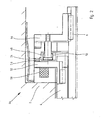
- the inner spindle 6 and the outer spindle 4 can be non-rotatably connected to one another via a coupling 44, as they are, for example, in FIG. 2 is shown.
- a coupling 44 is a commercially available electromagnetic gear coupling, so that only the basic principle is to be described here. Of course, other constructions can be used.
- a coupling flange 46 is attached to the inner spindle 6, a coupling flange 46, on which a displaceable in the axial direction of the coupling ring 48 is mounted.
- This movable coupling ring 48 is biased by tension springs 50 into a position in which the clutch is disengaged.
- an axially fixed coupling ring 52 is mounted on the outer spindle 4. Both coupling rings 48, 52 each have a spur gear teeth 54 and 56, which are engaged with the clutch 44 engaged. In the illustrated embodiment, the operation takes place, ie the closing of the clutch 44 via a mounted in the spindle housing 2 electromagnet 58, in the energization of the axially movable coupling ring 48 is moved to the left in the engaged position, so that the inner spindle 6 is rotatably connected to the outer spindle 4.
- the coupling 44 according to the invention thus makes it possible, for example, to connect the two spindles 4, 6 in a torque-proof manner to each other in hard-to-machine materials and to control both motors, so that a high torque is available for applying the cutting force.
- the motor which does not have to transmit cutting force i. in the present embodiment, the drive motor 22 of the inner spindle 6 is designed with a lower power than the drive motor 20 of the outer spindle 4, since this must transmit the cutting force.
- the drive motor 20 of the outer spindle 4 is then activated, so that the inner spindle 6 is practically "dragged" when the clutch is engaged. Since the drive motor 22 of the inner spindle 6, which is only required for cutting edge adjustment or other tasks, can be kept very small, the spindles 4, 6 can be made extremely compact.
- both standard tools i. Tools without compensation device, as well as compensation tools on the tool clamping device 34 shown are changed.
- the internal coolant / lubricant supply for KSS (emulsion, oil) or air can be performed.
- blowing air can be provided for cleaning the spindle and tool surfaces.
- MMKS small quantities of coolant
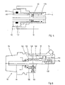
- FIG. 3 is a variant of in FIG. 1 shown tool clamping device 34 shown.
- the outer spindle 4 via angular contact ball bearings 8, 10 (and other ball bearings, not shown) stored in the spindle housing 2.
- the inner spindle 6 passes through - similar to the above-described embodiment - the pull rod 32nd
- the clamping element 40 is screwed for actuating the collet 38 and for ejecting the tool holder 60 inserted into the cone seat 36.
- FIG. 3 is the end portion of the inner spindle 6 to the left out of the pull rod 32 and has at its periphery a plurality of recesses through which a toothing 62 is formed.
- a compensation tool When using a compensation tool (lower half in FIG. 3 ) This has an actuating shaft 64, which is also frontally designed with a toothing 66.
- the two end-side teeth 62, 66 When inserting the tool holder 60 in the cone seat 36, the two end-side teeth 62, 66 are brought into engagement, whereby the inner spindle 6 is rotatably connected to the actuating shaft 64, so that on this example.
- the compensation of the cutting tool is controllable.
- the length of the protruding from the pull rod 32 end portion of the inner spindle 6 is selected so that when clamping a standard tool between a HSK coolant tube 68 and provided with the toothing 62 end face of the inner spindle remains an axial gap, so that no collision can take place.
- the control of the coupling process between the compensation tool (lower half in FIG. 3 ) and the inner spindle 6 can be effected by the latter spring-loaded in the outer spindle 4 is guided, so that in an incorrect coupling process, the inner spindle 6 is moved by running up the teeth 62, 66 to each other to the right.
- This axial displacement can be interrogated via suitable sensors and a corresponding error signal can be given to the machine control.
- FIG. 4 An embodiment is shown in which this disadvantage is overcome.
- an intermediate bushing 122 which extends beyond the toothing 62 and engages sealingly around the outer circumference of the end section of the adjacent HSK coolant tube, is rotatably formed on the end section of the inner spindle 6 carrying the toothing 62.
- an O-ring 124 is received in an annular groove of the intermediate sleeve 122.
- the coolant tube 68 thereby rotates at the same speed as the inner spindle 6, so that upon use of the in FIG.
- FIG. 5 By way of example, some tools 70 are shown, as they can be used in the above-described spindle assembly 1.
- the tool 70 is designed with a boring bar with bending clamp holder 72, wherein the radial adjustment of the Biegeklemmhalters 72 and thus the tool cutting edge 74 is effected by actuation of the coupled to the inner spindle 6 actuating shaft 64.
- the tool shown below is designed as an eccentric, wherein via the actuating shaft 64 and a displacement permitting coupling a tool cutting 74 bearing eccentric shaft 76 is driven.
- the tool 70 is performed with a facing head 78, via which a planing, chamfering, cone or ball turning is possible.
- the tool can be designed with a rotary swivel head 80, wherein a driver 79 can serve to prevent rotation.
- the embodiment arranged underneath shows a combination tool, in which two axially and radially offset tool cutting edges 74 are provided, which allow drilling or boring at different cutting speeds.
- the tool cutting edge 82 rotates at the speed of the outer spindle, while the tool cutting edge 74 is driven via the coupled to the inner spindle 6 actuating shaft 64.
- the lowest symbol stands for a rotary swivel head for die milling.
- FIG. 6 At the bottom left, a variant of a tool 70 is shown, in which the inner spindle 6 of the spindle assembly 1 is used for balancing the tool 70.
- This has an integrated balancing device 84 which can be driven by the actuating shaft 64 coupled to the inner spindle 6.
- a balancing ring 86 On the actuating shaft 64, a balancing ring 86 is attached, which has an imbalance.
- the balancing ring 86 meshes with a balancing wheel 88, which in turn meshes with another, in the tool 70 rotatably mounted balancing ring 90. That is, a rotation of the balancing ring 86 in the one direction of rotation is converted via the balancing wheel 88 in a rotation of the balancing ring 90 in the other direction of rotation.
- the two balancing rings 86, 90 can bring the two imbalances of the rings in a relative position to each other, in which an imbalance M of the outer spindle 4 is compensated, so that with the tool 70 a high-precision manufacturing is possible, the imbalance U during the machining process with high dynamics can be minimized.
- the balancing device 84 is integrated in the tool 70. This has the advantage that the spindle assembly 1 can be performed with a very short distance to the tool 70, since no balancing balancing masses need to be mounted in front of the front spindle bearing for balancing.
- the boring bar can be designed at an axial distance from the tool cutting edge with measuring nozzles.
- the supply of the measuring air takes place from the inside over the axial bore 31 of the inner spindle 6.
- a measuring section is performed, placed behind the cutting edge measuring nozzles placed in the measuring position and the bore then finished after measuring and a possible compensation by driving the inner spindle 6, the hole in the retreat become. That is, processing and measurement are carried out practically in one operation, so that the main time is shortened.
- a suitable drive eg. Hydraulic cylinder.
- FIG. 7 shows a tool 70 with integrated gear 92, over which the rotational speeds of the inner and outer ⁇ enspindel 6, 4 are again variable.
- This in FIG. 7 shown tool is used, for example.
- a housing 96 of the transmission 92 is rotatably connected to the steep taper 94.
- the coupling to the inner spindle 6 actuating shaft 64 is rotatably mounted in the interior of the housing 96 and drives a ring gear 98 at.
- the ring gear meshes with a planet gear 100 which is rotatably supported in the housing 96.
- the planet gear 100 in turn meshes with an internal gear 102, which is non-rotatably mounted on a rotatable output shaft 104 mounted in the housing 96.
- This output shaft 104 carries a drill rod 106 of the tool 70.
- the rotational speed of the drill rod 106 will vary by suitably driving the inner spindle 6 and the outer spindle 4 in a wide speed range.
- one of the two drive motors 20, 22 can be stopped or taking advantage of the maximum relative speed of the two spindles 4, 6, ie, counterclockwise rotation of a spindle and clockwise rotation of the other spindle, a superposition of the two speeds including the additional ratio of the transmission 92 can be achieved.
- other transmission designs than the illustrated transmission 92 with ring gear 98, planetary gear 100 and inner wheel 102 may be used.
- inner spindle 6 and outer spindle 4 run concentric with each other.
- This variant has the advantage that the imbalance of the spindle assembly 1 is very low. If this spindle assembly 1 is to be used as a compensation spindle, the eccentricity on the tool 70 (see FIG. 5 above) are introduced.
- both oriented (HSK-A) and non-oriented tools (HSK-E) can be loaded into the spindle arrangement 1. For non-oriented tools this can be provided with a stop that can be detected by the machine tool control and taken over as the zero point for the cutting tool 74.
- FIG. 8 shows a solution of such a compensation tool 70, in which the eccentricity is introduced via the tool, which is provided with a zero point adjustment.
- a tool 70 is designed with a rotation stop.
- the tool has a shank 132 with taper shank 94 and carries a bending clamp holder 72 with a tool cutting edge 74.
- the taper shank is inserted into the outer spindle 4 so that the tool cutting edge 74 rotates at the speed of the outer spindle 4.
- the actuating shaft 64 is mounted, which - for example, on the in FIG. 3 shown toothing - is in rotary engagement with the inner spindle.
- the bearing of the actuating shaft 64 via angular contact bearings 130, which are received in the axial bore of the shaft 132.
- a control surface 134 is formed, on which a radial pin 136 is supported, which acts on the Biegeklemmhalter 72 in the radial direction.
- a circumferential groove 138 is formed on the outer circumference, which does not completely encompass the outer circumference of the actuating shaft 64, but for example at an angle of 340 °, so that an end-face abutment surface is created.
- a stopper pin 140 is inserted, which dips with its end portion in the circumferential groove 138.
- the relative position between shaft 132 and actuating shaft 64 is changed with a predetermined direction of rotation until the stopper pin 140 abuts the groove in the circumferential direction limiting face - the zero position of the cutting edge 74 is positioned so accurately.
- the relative movement, ie the feed movement of the tool cutting edge 74 is limited by the Umgriffswinkel the groove.
- the referencing is done by a radial stop for limiting the angle of rotation between the shaft 132 and the actuating shaft 64.
- the feed movement via a ball screw spindle or the like, in which the spindle rotates and the mother performs an axial movement.
- the referencing for setting the relative rotational position can also be done by running the nut on an axial stop.
- the spindle assembly 1 can also be performed with an eccentrically mounted in the outer spindle 4 inner spindle 6.
- This type of spindle assembly 1 makes complex constructed Einttingkmü superfluous, so that can be used on standard tools.
- the disadvantage of this solution is that the cutting force on the inner spindle 6 must be applied so that the drive motor 22 is greater than to choose in the above embodiment.
- FIG. 9 is a spindle assembly 1 with eccentric inner spindle 6 is shown. Similar to the case of FIG. 1 explained embodiment, the outer spindle 4 is mounted on roller bearings 8, 10, 12, 14 and 15 in the spindle housing 2. The axis of rotation of the outer spindle 4 is in FIG. 9 provided with the reference numeral 108. The inner spindle 6 is mounted on roller bearings 16, 18, 19, 110 and 112 in the outer spindle 4. The axis of rotation 108 of the inner spindle 6 is offset by the dimension Z with respect to the axis of rotation 114 of the outer spindle 4.
- the drive of the outer spindle 4 is effected by the drive motor 20, the stator 26 is housed fixed to the housing and the rotor 28 is rotatably connected to the outer spindle 4.
- the stator 24 of the drive motor 22 of the Inner spindle 6 is also housed fixed to the housing, while the rotor 30 of the drive motor 22 is rotatably connected to the inner spindle 6 - that is, the rotor 30 is formed by the dimension Z eccentric to the stator 24.
- no additional coupling between the drive and spindle is needed, so that the unit builds very short axially.
- This construction can be realized with smaller eccentricity measures Z.
- the drive via gearbox, eg. Bevel gear or special compensating couplings, which also carry the central coolant supply.
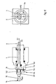
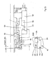
- FIG. 10 shows a basic principle according to which such a balancing of the compensation spindle can be performed. It is assumed that the inner and outer spindle 4, 6 and the tool 70 are not balanced. On the outer spindle nose 116, a balancing device 118 can be placed, which is arranged in front of the front spindle bearings, ie the rolling bearings 110, 112. On the spindle housing 2 an accelerometer 120 is placed so that resulting from the imbalance accelerations can be detected. The larger diameter of the outer spindle 4 comes against the required balancing capacity. In a non-pre-balanced tool 70, the balance in any angular position of the inner spindle 6 can be done.
- the balancer 118 can not compensate for the change in the imbalance size and location fast enough so that it may become necessary to pre-balance the tool 70.
- a disadvantage of this solution is that the outer spindle nose 116 requires a considerable axial space.
- the balancing device 118 is arranged on the spindle side.
- FIG. 11 shows a variant in which the balancing device is arranged on the tool side.
- the inner spindle 6 is eccentrically stored in the outer spindle 4.
- the tool 70 is inserted into the cone seat 36, which is arranged on the inner spindle 6 in the case of eccentric spindle arrangements. Due to the eccentric arrangement of the inner spindle 6, the spindle arrangement has a not inconsiderable imbalance.
- the tool 70 is provided with a balancing device 84. This balancing device 84 is mounted on the outer circumference of the shank 132 of the tool 70 via a bearing 142. According to FIG.
- the balancing device 84 carries a balancing weight 144, which is non-rotatably connected via a fixing 146 with the outer spindle - in the illustrated case with the end face of the outer spindle nose 116. D. h., The balance weight 144 rotates together with the outer spindle 4 and is chosen so that the imbalance mass of the tool and the inner spindle is balanced.
- FIG. 12 Finally shows functional positions of an embodiment in which the actuation of the drawbar 32 and the coupling 44 via a common actuator, so that the unit is constructed very compact.
- the solution shown is guided on the inner spindle 6 a sliding axially displaceable sliding sleeve 148 which is rotatably connected via a feather key with the inner spindle 6.
- an internal friction surface 150 is formed, which is engageable with a correspondingly formed
- the discoursereib resources 152 is executed on a radial collar which dips into a receptacle 154 of the sliding sleeve 148.
- the sliding sleeve 148 carries on its outer circumference two bearings 156, on which a piston 158 is mounted. This piston is rotatably received in a cylinder housing 160. A circumferential annular collar 162 of the piston 158 and the cylinder housing 160 form two cylinder chambers 164 and 166, which are separated by the annular collar 162 frontally.
- the cylinder housing 160 is axially displaceably mounted in the spindle housing 2 and is biased by at least one spring 174 in the axial direction away from a shoulder of the spindle housing.
- a key 175 prevents rotation of the cylinder housing 160.
- On the cylinder housing 160 is further mounted a spring plate 176 via a plurality of bolts 178 and tension springs 180.
- the spring plate is biased against a clutch bearing 182 which is mounted on a pressure ring 184. This surrounds the inner spindle 6 and can be brought into contact with the adjacent end face 186 of the sliding sleeve 148.
- FIG. 12 and 13 show the spindle assembly in the operating states “coupled”, “uncoupled”, tool “cocked” and “relaxed”. These four operating states can be achieved by cooperation of the piston 158 and one based on FIG. 13 set switching piece 188 described.
- the piston 158 has a piston rod 190 extending toward the pull rod 32 in which a in the Representation according to FIG. 13 downwardly opening cam groove 192 is formed.
- This tax is in FIG. 13 shown below as a detail. Accordingly, this has in the view from below two axially offset from each other groove sections, wherein the in FIG. 13 overhead groove portion - in the following clamping groove 194 called the tool voltage controls, while a bottom groove portion - hereinafter called coupling groove 196 - the clutch between the inner and outer spindle 6, 4 controls.
- the axial movement of the piston 158 is limited. Which of said grooves 194, 196 is effective is an in FIG.
- control determines that by means of a Hubmagenten so within the cam groove 192 is slidably that it can be selectively brought into coincidence with the clamping groove 194 or the coupling groove 196.
- control piece 198 by means of the solenoid in the illustration according to FIG. 13 moved upwards perpendicular to the drawing plane.
- Both cylinder chambers 164, 166 can be acted upon with pressure medium to cause an axial displacement of the piston 158 and the cylinder housing 160.
- a sliding stop 168 of the drawbar 82 is in an in FIG. 12 Position shown below spaced from an actuating surface 170 of the piston 158. In this position, the pull rod 32 is biased by the tension springs 42, so that the tool is tensioned. As further out FIG. 12 below, the inner friction surface 150 and the technicallyreib components 152 and the end face 186 and the pressure ring 186 are at an axial distance from each other, so that the clutch is released and no rotational connection between the inner spindle 6 and outer spindle 4 is present.
- the cylinder chamber 166 is acted upon by pressure medium, so that this from the position according to FIG. 12 is moved to the left and runs on a housing stop 202 of the cylinder housing 160.
- the control piece 198 is located at a small distance to a rear edge 204 of the clamping groove 194.
- the actuating surface 170 runs on the pull rod 32, so that they are shifted by the release path to the left is - the tool is relaxed, the inner spindle 6 and the outer spindle 4 are decoupled.
- control piece 198 When coupling the control piece 198 is driven by the solenoid in a position in which it in the coupling groove 196 (down in FIG. 13 immersed). In the coupled state, the control piece 198 abuts on a coupling flank 206 or is at a short distance therefrom.
- the right cylinder chamber 166 is acted upon by pressure medium, so that the piston 158 from the in FIG. 12 Position shown above is moved to the left and runs with a coupling edge 208 on the contact piece 198.
- the cylinder housing 160 moves with the pressure ring 184 to the right, so that the adhesion between the friction surfaces 150, 152 and the contact between the pressure ring 184 and the end face 186 is canceled - the spindles 4, 6 are decoupled, the tool is stretched.
- the spindle assembly In the coupled state of the two spindles 4, 6, the spindle assembly is entrained by the strong drive motor 20 of the outer spindle 4.
- coupled Outer and inner spindle are two operating states conceivable. Once the more motorized spindle can be used to accelerate and decelerate the lower motorized spindle, so that the acceleration and deceleration time can be reduced.
- the available power at the tool cutting edge can be increased by driving in master-slave mode.
- the tool is further tensioned since the axial distance to the sliding stop 168 in the actuating surface 170 is increased by the axial displacement of the piston 158.
- a play "s” may be formed between the end face of the piston 158 and the adjacent housing wall. This can be exploited to set a bias of the spindle bearing via the piston 158 and possibly the sliding sleeve 148.
- the bearings 156 practically form a movable bearing of the spindle assembly which is displaceable in the axial direction. By varying the pressure in the cylinder chamber 164, the preload of the spindle bearing can be adjusted in the presence of play s. D.
- the pressure in the cylinder chamber 164 can be varied and thus the bias of the spindle bearing can be adapted to different operating conditions. In the event that such a variant is not desired, can also be dispensed with the game s, so that the piston 158 runs in its right end position on the cylinder housing 160.
- a spindle assembly having an outer spindle and a concentric thereto or eccentrically mounted to inner spindle. Both spindles is assigned its own drive, so that, for example, a compensation by setting a speed difference between the inner and outer spindle is possible.
- the drive power can be optimized if the inner and outer spindle by means of a coupling rotatably connected to each other. As a result, both drive motors can be optimally adapted to the respective tasks (delivery, transmission of cutting force).
- the smaller drive motor for the feed movement can be provided with a comparatively large translation.
Landscapes
- Engineering & Computer Science (AREA)
- Mechanical Engineering (AREA)
- Turning (AREA)
- Gripping On Spindles (AREA)
- Constituent Portions Of Griding Lathes, Driving, Sensing And Control (AREA)
- Drilling And Boring (AREA)
Description
- Die Erfindung betrifft eine Spindelanordnung für eine Werkzeugmaschine gemäß dem Oberbegriff des Patentanspruchs 1.
- Eine derartige Spindelanordnung ist aus der
deutschen Patentanmeldung DE 197 122 38 der Anmelderin bekannt. Bei dieser Lösung ist eine Innenspindel in einer Außenspindel gelagert, wobei beiden Spindeln ein eigener Antrieb zugeordnet ist. Beide Antriebe lassen sich synchron miteinander oder mit einer Drehzahldifferenz antreiben. Bei einer Variante dieser bekannten Lösung ist die Spindelanordnung als Kompensationsspindel ausgeführt, wobei die Innenspindel exzentrisch in der Außenspindel gelagert ist. Durch Einstellung einer Drehzahldifferenz zwischen exzentrisch gelagerter Innenspindel und der Außenspindel kann dann eine Radialverstellung der Werkzeugschneiden erfolgen. - In der gattungsgemäßen Patentanmeldung ist eine alternative Lösung beschrieben, gemäß der die Innenspindel koaxial zur Außenspindel gelagert ist und an ihrem Außenumfang mit einer Steuerfläche versehen ist, gegen die ein Radialstift vorgespannt ist. Durch Verdrehung der Innenspindel gegenüber der Außenspindel kann dieser Stift in Radialrichtung bewegt werden. Diese Radialverschiebung wird auf einen Biegeklemmhalter für eine oder mehrere Werkzeugschneiden übertragen, so daß auch bei dieser Lösung mit äußerst einfachem vorrichtungstechnischem Aufwand eine exakte Radialverstellung während der Bearbeitung ermöglicht ist.
- Trotz des vergleichsweise einfachen Aufbaus der vorbeschriebenen Lösungen zeigte es sich bei der Realisierung dieses Konzepts, daß insbesondere im Antriebsbereich noch ein erheblicher Aufwand erforderlich ist, um den Anforderungen, wie bspw. schnelle Einstellung von Drehzahländerungen und hoher Schnittgeschwindigkeiten auch bei schwer zu zerspanenden Materialien zu genügen.
- Aus der
US 4,573,379 ist eine Maschine mit einer drehbaren Spindel für ein Werkzeug oder Werkstück bekannt und eine Vorrichtung mit einem Wälzkörper-Schneckengetriebemechanismus, welcher koaxial an der Spindel angeordnet ist. Über diesen Mechanismus ist ein Teil längs der Spindel axial beweglich. - Aus der
DE 299 17 510 U1 ist eine Spindeleinheit für eine Werkzeugmaschine bekannt, welche in einem motorseitigen Motorspindelgehäuse einen elektrisch angetriebenen Antriebsmotor für eine Motorspindel und eine Hauptspindel mit einem rotierenden Bearbeitungswerkzeug aufweist. Es ist ein Zustellsystem und ein Steigenträger vorgesehen, der über eine Stelleinrichtung quer zur Achse des Werkzeugs verstellbar gelagert ist. Die Schnittgeschwindigkeit ist primär durch die Drehung des Werkzeugs erzielt. - Demgegenüber liegt der Erfindung die Aufgabe zugrunde, eine Spindelanordnung zu schaffen, die mit minimalem vorrichtungstechnischem Aufwand die schnell Einstellung von Drehzahländerungen, und die Realisierung hoher Zerspanungsleistungen ermöglicht.
- Diese Aufgabe wird durch eine Spindelanordnung mit den Merkmalen des Patentanspruchs 1 gelöst.
- Erfindungsgemäß hat die Spindelanordnung eine Kupplung, über die beide Spindeln miteinander drehfest koppelbar sind, so daß die Antriebsmomente beider Antriebsmotoren genutzt werden können, um hohe Zerspanungsleistungen zu ermöglichen. Erfindungsgemäß wird es bevorzugt, wenn der die Schnittkraft übertragenden Spindel, bspw. der Außenspindel ein vergleichsweise großer Motor zugeordnet ist, während der die Schneidenverstellung (Kompensation), vornehmende Spindel relativ klein gehalten werden kann, so daß die Spindel sehr kompakt aufgebaut ist. Bei dieser Variante erfolgt das Beschleunigen und Abbremsen der Innenspindel über den starken Antrieb der Außenspindel, während der kleinere Antrieb der Innenspindel nur die Schneidenverstellung übernimmt.
- Da bei der erfindungsgemäßen Lösung ein Motor kleiner als bei herkömmlichen Konstruktionen ausgeführt werden kann, dürfte die Spindelanordnung auch kostengünstiger herstellbar sein.
- Vorzugsweise werden die Antriebsmotoren der Spindeln als Einbaumotoren ausgeführt, die koaxial zu den Spindeln im Spindelgehäuse angeordnet sind.
- Die Kupplung kann als kraft- oder formschlüssige Kupplung ausgeführt sein. Eine besonders einfach aufgebaute und robuste Variante dürfte die Ausbildung als Zahnkupplung, bspw. etwa in Form einer Hirth-Kupplung sein, die das Übertragen hoher Drehmomente ermöglicht. Bevorzugt werden jedoch Reibkupplungen.
- Bei Lösungen, bei denen die Innenspindel koaxial zur Außenspindel gelagert ist, wird ein Werkzeug vorzugsweise in der Außenspindel gespannt, deren Antriebsmotor somit größer als der Zustellmotor der Innenspindel ist. Dabei kann eine Zugstange zum Betätigen von Spannzangen der Werkzeugaufnahme von der Innenspindel durchsetzt sein.
- Für den Fall, daß die Innenspindel koaxial zur Außenspindel gelagert ist und eine Kompensation der Werkzeugschneiden gewünscht ist, wird die Spindelanordnung mit einem sog. Kompensationswerkzeug betrieben, in das die Einrichtung zur Schneidenverstellung integriert sind. In diesem Fall wird die Drehbewegung der Innenspindel über eine geeignete form- oder kraftschlüssige Kupplung auf eine Betätigungswelle des Werkzeugs übertragen. Diese Betätigungswelle ist im Fall eines Kompensationswerkzeugs eine Exzenterwelle. Selbstverständlich können über diese Betätigungswelle auch andere Funktionen des Werkstückes, bspw. eine Wuchteinrichtung, oder ein Getriebe zur Anpassung der Werkzeugdrehzahl oder Meßköpfe etc. gesteuert werden.
- Um Beschädigungen der Spindelanordnung zu vermeiden, kann die mit der Betätigungswelle zu koppelnde Innenspindel in Axialrichtung federnd im Spindelgehäuse aufgenommen sein, so daß im Fall einer fehlerhaften Ankopplung und einer daraus resultierenden axialen Verschiebung der Innenspindel diese erfaßt und ein Fehlersignal an die Maschinensteuerung abgegeben werden kann.
- Die erfindungsgemäße Spindelanordnung kann auch mit einer exzentrisch gelagerten Innenspindel ausgeführt sein. In diesem Fall wird das Werkzeug in der Innenspindel gespannt, so daß der Antriebsmotor für die Innenspindel größer als beim vorbeschriebenen Ausführungsbeispiel ausgeführt wird. In diesem Fall läßt sich eine besonders kompakte Spindelanordnung ausbilden, in dem die Statoren der Antriebe für Außen- und Innenspindel koaxial zueinander angeordnet sind, so daß der Rotor des Antriebsmotors der Innenspindel exzentrisch im zugeordneten Stator läuft.
- Der Aufwand zur Ansteuerung der Spindelanordnung ist besonders gering, wenn eine Werkzeugspannvorrichtung und die Kupplung über eine gemeinsame Betätigungseinrichtung aussteuerbar sind.
- Als Betätigungseinrichtung wird bei einem bevorzugten Ausführungsbeispiel ein hydraulisch betätigter Kolben verwendet, über den einerseits die Kupplung zur Verbindung der Innen- und Aussenspindel und andererseits die Werkzeugspannvorrichtung betätigbar ist.
- Bei einem besonders einfach ausgeführten Ausführungsbeispiel ist dieser Kolben als Hohlkolben ausgeführt, der über eine Schiebehülse auf einer der Spindeln, vorzugsweise der Innenspindel axialverschiebbar und drehfest gelagert ist. Über diese Schiebehülse kann eine drehfeste Verbindung mit der anderen Spindel - im vorliegenden Fall der Aussenspindel - hergestellt werden, während über den Kolben oder die Schiebehülse bei einer Axialverschiebung auch die Werkzeugspannvorrichtung durch Axialverschiebung betätigt wird.
- Bei einem vorteilhaften Ausführungsbeispiel kann der Kolben auch zur Einstellung einer Lagervorspannung verwendet werden.
- Bei einem besonders bevorzugten Ausführungsbeispiel ist der Kolben über Lager auf der Schiebehülse und damit der Innenspindel abgestützt. Diese Lager bilden ein Loslager der Spindelanordnung. Erfindungsgemäß kann die Lagervorspannung durch Druckbeaufschlagung des Kolbens variiert werden.
- Wie vorstehend erwähnt, können durch die Axialposition des Kolbens die Betriebszustände Kuppeln, Entkuppeln, Spannen, Entspannen gesteuert werden. Die unterschiedlichen Axialpositionen lassen sich bei einer vorteilhaften Variante über eine Steuereinrichtung steuern. Diese Steuereinrichtung kann beispielsweise ein Steuerstück haben, das in einer Steuernut des Kolbens geführt ist und das in Überdeckung mit mehreren Anschlagflächen der Nut bringbar ist. Die Verschiebung des Steuerstücks zur Aktivierung der unterschiedlichen Anschläge kann beispielsweise über einen Hubmagneten oder eine andere geeignete Stelleinrichtung erfolgen.
- Bei einem weiteren bevorzugten Ausführungsbeispiel der Erfindung ist an dem von der Kupplung entfernten Endabschnitt des Zylindergehäuses ein Druckring vorgesehen, der zum Kuppeln in Reibschluss mit der Schiebehülse bringbar ist. Das übertragbare Kupplungsmoment wird dabei über eine federvorgespannte Federplatte bestimmt. D. h., die Verbindung zwischen der Innenspindel und der Aussenspindel erfolgt einerseits über die Kupplung und andererseits über den Druckring.
- Es wird bevorzugt, wenn das den Kolben aufnehmende Zylindergehäuse selbst axialverschiebbar im Spindelgehäuse geführt ist, so dass der vorbeschrieben Druckring auch durch Axialverschiebung des Zylindergehäuses in seine Kupplungsposition bringbar ist.
- Bei nicht orientierten Werkzeugen werden diese mit einer Referenziereinrichtung ausgeführt, über die durch geeignete Ansteuerung von Innen- und Außenspindel seine Nulllagenpositionierung der Werkzeugschneide durchführbar ist.
- Diese Referenziereinrichtung wird vorzugsweise als Drehanschlag mit einem Anschlagkörper ausgeführt, der drehfest im Werkzeugkopf oder in der Betätigungswelle aufgenommen ist und der mit einem Endabschnitt in eine Umfangsnut der Betätigungswelle bzw. des Werkzeugkopfs eintaucht, so dass der Anschlagkörper bei Einstellung der Drehzahldifferenz in eine Anschlagposition gebracht werden kann, die die Nullage der Werkzeugschneide kennzeichnet.
- Besonders vorteilhaft ist es, wenn die Umfangsnut den Aussenumfang der Betätigungswelle nicht vollständig umgreift, so dass der Anschlagkörper in der Nulllage auf eine Stirnfläche der Umfangsnut aufläuft.
- Alternativ kann die Referenziereinrichtung auch einen Axialanschlag aufweisen, auf den ein axial verschiebbarer Teil des Werkzeugs zur Einstellung der Nullposition aufläuft. Dieser axial verschiebbare Teil kann beispielsweise durch eine Mutter einer Gewinde- oder Kugelumlaufspindel gebildet sein, die mit der Betätigungswelle zusammenwirkt oder als Betätigungswelle ausgebildet ist, wobei die axialverschiebbare Mutter auf einen Axialanschlag aufläuft.
- Sonstige vorteilhafte Weiterbildungen der Erfindung sind Gegenstand der weiteren Unteransprüche.
- Im folgenden werden bevorzugte Ausführungsbeispiele der Erfindung anhand schematischer Zeichnungen näher erläutert. es zeigen:
-
Figur 1 eine schematische Schnittdarstellung einer erfindungsgemäßen Spindelanordnung mit koaxialer Außenund Innenspindel; -
Figur 2 eine Kupplung für die Spindelanordnung ausFigur 1 ; -
Figur 3 eine Spindelanordnung mit koaxialer Innenund Außenspindel, in die alternativ ein Standardwerkzeug und ein Kompensationswerkzeug eingespannt ist; -
Figur 4 eine Variante der Spindelanordnung ausFigur 3 ; -
Figur 5 Werkzeugkonzepte, die bei einer erfindungsgemäßen Spindelanordnung einsetzbar sind; -
Figur 6 ein Werkzeug mit integrierter Wuchteinrichtung; -
Figur 7 ein Werkzeug mit integriertem Getriebe zur Änderung der Werkzeugdrehzahl; -
Figur 8 ein Werkzeug mit Drehanschlag zur Nulllagenjustierung; -
Figur 9 ein weiteres Ausführungsbeispiel einer Spindelanordnung mit exzentrischer Innenspindel und -
Figur 10 eine Wuchteinrichtung für die Spindelanordnung ausFigur 9 ; -
Figur 11 eine werkzeugseitige Wuchteinrichtung, -
Figur 12 eine Spindelanordnung, bei der eine Kupplung und eine Werkzeugspannvorrichtung gemeinsam betätigbar sind und -
Figur 13 die Spindelanordnung ausFigur 12 bei entspanntem Werkzeug. - In
Figur 1 ist ein erstes Ausführungsbeispiel einer erfindungsgemäßen Spindelanordnung 1, auch Kompensationsspindel genannt, dargestellt. In einem Spindelgehäuse 2 sind eine Außenspindel 4 und eine koaxial zu dieser angeordnete Innenspindel 6 gelagert. In dem Spindelgehäuse 2 sind Wälzlager, bspw. Schrägkugellager 8, 10, 12 und 14 zur Lagerung der Außenspindel 4 abgestützt. Die Innenspindel 6 durchsetzt die Außenspindel 4 und ist über mehrere Wälzlager 16, 18 in der Außenspindel bzw. im Spindelgehäuse geführt. Der Antrieb der Spindeln 4, 6 erfolgt über als Einbaumotoren ausgeführte Antriebsmotoren 20 bzw. 22, deren Statoren 24, 26 gehäusefest aufgenommen sind, während die Rotoren 28, 30 auf der Außenspindel 4 bzw. der Innenspindel 6 gelagert sind. - Bei dem gezeigten Ausführungsbeispiel wird die Innenspindel von einer Axialbohrung 31 durchsetzt, die zur Zuoder Abführung von Kühl-/Schmiermittel, Meßluft, Druckluft etc. dient.
- Der sich an die beiden Wälzlager 16, 18 nach links anschließende Teil der Innenspindel 6 durchsetzt eine hohle Zugstange 32 einer Werkzeugspannvorrichtung 34 gelagert. Die Zugstange 32 läßt sich mittels eines Schiebemechanismus 36 zum Spannen eines Werkzeuges in Axialrichtung verschieben. Die Innenspindel 6 könnte auch über ein Loslager in der Zugstange 32 gelagert sein, das die Axialverschiebung während des Entspannens mitmacht. Beim dargestellten Ausführungsbeispiel ist die Werkzeugspannvorrichtung 34 vorzugsweise als Steilkegel-Spannvorrichtung ausgeführt, in deren Kegelaufnahme 36 der Werkzeughalter eingesetzt wird. Die Werkzeugspannvorrichtung 34 hat eine Spannzange 38, die durch an der Zugstange 32 befestigte Spannelemente 40 zum Spannen des Werkzeuges in ihre Spreitzstellung bringbar sind. Beim Verschieben der Zugstange 32 nach links (
Figur 1 ) wirken die Spannelemente 40 als Auswerfer zum Lösen des Werkzeuges. Üblicherweise ist dem in die Kegelaufnahme 36 eingesetzten Werkzeughalter ein Kühlmittelröhrchen ausgebildet, so daß Kühlmittel über die Axialbohrung 31 und das Kühlmittelröhrchen in den Verspanungsbereich geführt werden kann. Die Zugstange 32 ist durch Spannfedern 42 in ihre Spannposition vorgespannt. - In die vorbeschriebene Werkzeugaufnahme lassen sich Standardwerkzeuge mit Norm-HSK-Kühlmittelröhrchen oder aber auch Kompensationswerkzeuge oder sonstige Werkzeuge mit Sonderfunktionen einsetzen, über die bspw. ein Radialverstellung der Werkzeugschneide während der Zerspanung möglich ist.
- Bei dem vorbeschriebenen Ausführungsbeispiel ist die Werkzeugspannvorrichtung 34 in der Außenspindel 4 aufgenommen, so daß die Schnittkraft von dieser Spindel aufgebracht werden muß. Der Antriebsmotor 20 der Außenspindel 4 ist bei dem gezeigten Ausführungsbeispiel mit größerer Leistung als der Antriebsmotor 22 der Innenspindel 6 ausgeführt, da über diesen lediglich die Sonderfunktionen, wie bspw. Schneidenverstellung durchgeführt werden müssen, für die wesentlich weniger Drehmoment als für die Übertragung der Schnittkraft aufgebracht werden muß. Beim gezeigten Ausführungsbeispiel sind die Antriebsmotoren 20, 22 im Axialabstand zueinander angeordnet. Alternativ könnten die Motoren jedoch auch ineinander liegend angeordnet sein.
- Erfindungsgemäß lassen sich die Innenspindel 6 und die Außenspindel 4 über eine Kupplung 44 drehfest miteinander verbinden, wie sie bspw. in
Figur 2 dargestellt ist. Es handelt sich um eine handelsübliche elektromagnetische Zahnkupplung, so daß hier lediglich das Grundprinzip beschrieben werden soll. Selbstverständlich sind auch andere Konstruktionen einsetzbar. Wesentlich ist, dass die Funktion der Kupplung bei den Antriebsmomenten und den hohen Drehzahlen (12 000 U/min) gewährleistet ist. GemäßFigur 2 ist an der Innenspindel 6 ein Kupplungsflansch 46 befestigt, an dem ein in Axialrichtung verschiebbarer Kupplungsring 48 gelagert ist. Dieser bewegbare Kupplungsring 48 ist über Spannfedern 50 in eine Position vorgespannt, in der die Kupplung außer Eingriff ist. An der Außenspindel 4 ist ein in Axialrichtung feststehender Kupplungsring 52 gelagert. Beide Kupplungsringe 48, 52 haben jeweils eine Stirnverzahnung 54 bzw. 56, die bei eingerückter Kupplung 44 in Eingriff miteinander stehen. Bei dem dargestellten Ausführungsbeispiel erfolgt die Betätigung, d.h. das Schließen der Kupplung 44 über einen im Spindelgehäuse 2 gelagerten Elektromagneten 58, bei dessen Bestromung der axial bewegliche Kupplungsring 48 nach links in die Eingriffsposition verschoben wird, so daß die Innenspindel 6 drehfest mit der Außenspindel 4 verbunden ist. - Die erfindungsgemäße Kupplung 44 ermöglicht es somit, bspw. bei schwer zu zerspanenden Materialien die beiden Spindeln 4, 6 drehfest miteinander zu verbinden und beide Motoren anzusteuern, so daß ein hohes Drehmoment zum Aufbringen der Schnittkraft zur Verfügung steht. Erfindungsgemäß wird es bevorzugt, wenn derjenige Motor, der keine Schnittkraft übertragen muß, d.h. im vorliegenden Ausführungsbeispiel der Antriebsmotor 22 der Innenspindel 6 mit einer geringeren Leistung als der Antriebsmotor 20 der Außenspindel 4 ausgelegt wird, da dieser die Schnittkraft übertragen muß. Zum Beschleunigen oder Abbremsen der Spindeln 4, 6 wird dann lediglich der Antriebsmotor 20 der Außenspindel 4 angesteuert, so daß die Innenspindel 6 bei eingerückter Kupplung praktisch "mitgeschleppt" wird. Da der lediglich für die Schneidenverstellung oder sonstigen Aufgaben benötigte Antriebsmotor 22 der Innenspindel 6 sehr klein gehalten werden kann, können die Spindeln 4, 6 äußerst kompakt aufgebaut werden.
- Wie bereits vorstehend erwähnt, können sowohl Standardwerkzeuge, d.h. Werkzeuge ohne Kompensationseinrichtung, als auch Kompensationswerkzeuge über die gezeigte Werkzeugspannvorrichtung 34 gewechselt werden. Über die Axialbohrung 31 kann die interne Kühl-/Schmiermittelzufuhr für KSS (Emulsion, Öl) oder für Luft ausgeführt werden. Beim Werkzeugwechsel kann Blasluft für die Reinigung der Spindel- und Werkzeugfunktionsflächen bereitgestellt werden. Bei Mindermengen Kühlschmiermittel (MMKS) muss eine separate Bohrung vorgesehen werden.
- In
Figur 3 ist eine Variante der inFigur 1 dargestellten Werkzeugspannvorrichtung 34 dargestellt. Wie beim vorbeschriebenen Ausführungsbeispiel ist die Außenspindel 4 über Schrägkugellager 8, 10 (und weitere nicht dargestellte Kugellager) im Spindelgehäuse 2 gelagert. Die Innenspindel 6 durchsetzt - ähnlich wie beim vorbeschriebenen Ausführungsbeispiel - die Zugstange 32. Auf den inFigur 3 linken Endabschnitt der Zugstange 32 ist das Spannelement 40 zur Betätigung der Spannzange 38 und zum Auswerfen der in die Kegelaufnahme 36 eingesetzten Werkzeugaufnahme 60 aufgeschraubt. - Gemäß
Figur 3 steht der Endabschnitt der Innenspindel 6 nach links aus der Zugstange 32 hervor und hat an seinem Umfang eine Vielzahl von Ausnehmungen, durch die eine Verzahnung 62 gebildet ist. - Bei der Verwendung eines Kompensationswerkzeuges (untere Hälfte in
Figur 3 ) hat dieses eine Betätigungswelle 64, die stirnseitig ebenfalls mit einer Verzahnung 66 ausgeführt ist. Beim Einsetzen der Werkzeugaufnahme 60 in die Kegelaufnahme 36 werden die beiden stirnseitigen Verzahnungen 62, 66 in Eingriff gebracht, wodurch die Innenspindel 6 drehfest mit der Betätigungswelle 64 verbunden ist, so daß über diese bspw. die Kompensation der Werkzeugschneiden steuerbar ist. - Die Länge des aus der Zugstange 32 hervorstehenden Endabschnittes der Innenspindel 6 ist so gewählt, daß beim Spannen eines Standardwerkzeuges zwischen einem HSK-Kühlmittelröhrchen 68 und der mit der Verzahnung 62 versehenen Stirnfläche der Innenspindel ein Axialspalt verbleibt, so daß keine Kollision stattfinden kann.
- Die Kontrolle des Kupplungsvorganges zwischen dem Kompensationswerkzeug (untere Hälfte in
Figur 3 ) und der Innenspindel 6 kann dadurch erfolgen, daß letztere angefedert in der Außenspindel 4 geführt ist, so daß bei einem fehlerhaften Kupplungsprozeß die Innenspindel 6 durch Auflaufen der Verzahnungen 62, 66 aufeinander nach rechts bewegt wird. Diese Axialverschiebung kann über geeignete Aufnehmer abgefragt und ein entsprechendes Fehlersignal an die Maschinensteuerung abgegeben werden. - Nachteilig bei der in
Figur 3 dargestellten Lösung ist, dass es im Übergangsbereich zwischen dem HSK-Kühlmittelröhrchen und der Innenspindel zu Leckagen kommen kann. InFigur 4 ist ein Ausführungsbeispiel dargestellt, bei dem dieser Nachteil überwunden ist. Bei dieser Lösung ist an dem die Verzahnung 62 tragenden Endabschnitt der Innenspindel 6 drehfest eine Zwischenbuchse 122 ausgebildet, die sich über die Verzahnung 62 hinaus erstreckt und den Aussenumfang des Endabschnittes des benachbarten HSK-Kühlmittelröhrchen dichtend umgreift. Zur besseren Abdichtung ist dabei ein O-Ring 124 in einer Ringnut der Zwischenbuchse 122 aufgenommen. Das Kühlmittelröhrchen 68 dreht sich dabei mit der gleichen Geschwindigkeit wie die Innenspindel 6, so dass auf Verwendung des inFigur 4 oben dargestellten Standard-Werkzeuges die Leckage gegenüber der vorbeschriebenen Lösung sehr gering ist. Die Zugstange 32 umgreift mit ihrem Endabschnitt den Aussenumfang der Zwischenbuchse 122. In der Darstellung gemäßFigur 4 ist der Entspannungshub der Zugstange 32 strichpunktiert angedeutet. D. h, in dieser Hubposition befindet sich eine Ringstirnfläche der Zugstange 32 in Axialrichtung vor (links) der Stirnfläche der Zwischenbuchse 122. Zur Abdichtung der Zwischenbuchse 122 mit Bezug zur Innenspindel 6 sind im Umfangsbereich weitere Dichteinrichtungen 126 vorgesehen. Im Übrigen entspricht das vorbeschriebene Ausführungsbeispiel demjenigen ausFigur 3 , so dass weitere Erläuterungen entbehrlich sind. - In
Figur 5 sind beispielhaft einige Werkzeuge 70 dargestellt, wie sie in die vorbeschriebene Spindelanordnung 1 einsetzbar sind. Bei dem oben dargestellten Ausführungsbeispiel ist das Werkzeug 70 mit einer Bohrstange mit Biegeklemmhalter 72 ausgeführt, wobei die Radialverstellung des Biegeklemmhalters 72 und damit der Werkzeugschneide 74 durch Betätigung der an die Innenspindel 6 angekoppelten Betätigungswelle 64 erfolgt. - Das darunter abgebildete Werkzeug ist als Exzenterwerkzeug ausgeführt, wobei über die Betätigungswelle 64 und eine einen Versatz zulassende Kupplung eine die Werkzeugschneide 74 tragende Exzenterwelle 76 angetrieben wird.
- Bei dem darunter dargestellten Ausführungsbeispiel wird das Werkzeug 70 mit einem Plandrehkopf 78 ausgeführt, über das ein Planen, Fasen, Kegel- oder Kugeldrehen ermöglicht ist. Die Verstellung des Plandrehkopfs 78 erfolgt über die Betätigungswelle 64.
- Zur Bearbeitung von räumlich angeordneten Bohrungen und zum Kugeldrehen kann das Werkzeug mit einem Dreh-Schwenkkopf 80 ausgeführt werden, wobei ein Mitnehmer 79 als Verdrehsicherung dienen kann.
- Das darunter angeordnete Ausführungsbeispiel zeigt ein Kombiwerkzeug, bei dem zwei axial und radial versetzte Werkzeugschneiden 74 vorgesehen sind, die ein Bohren bzw. Ausdrehen mit unterschiedlichen Schnittgeschwindigkeiten ermöglichen. Dabei dreht sich die Werkzeugschneide 82 mit der Drehzahl der Außenspindel, während die Werkzeugschneide 74 über die an die Innenspindel 6 angekoppelte Betätigungswelle 64 angetrieben wird.
- Das unterste Symbol steht für einen Dreh-Schwenkkopf zum Gesenkfräsen.
- In
Figur 6 unten links ist eine Variante eines Werkzeugs 70 dargestellt, bei dem die Innenspindel 6 der Spindelanordnung 1 zum Wuchten des Werkzeuges 70 verwendet wird. Dieses hat eine integrierte Wuchteinrichtung 84, die von der an die Innenspindel 6 angekuppelten Betätigungswelle 64 antreibbar ist. - An der Betätigungswelle 64 ist ein Wuchtring 86 befestigt, der eine Unwucht aufweist. Der Wuchtring 86 kämmt mit einem Wuchtrad 88, das seinerseits mit einem weiteren, im Werkzeug 70 drehbar gelagerten Wuchtring 90 kämmt. D.h., eine Drehung des Wuchtrings 86 in die eine Drehrichtung wird über das Wuchtrad 88 in eine Drehung des Wuchtrings 90 in die andere Drehrichtung umgesetzt. Durch diese Relatiwerdrehung der beiden Wuchtringe 86, 90 lassen sich die beiden Unwuchten der Ringe in eine Relativposition zueinander bringen, in der eine Unwucht M der Außenspindel 4 kompensiert ist, so daß mit dem Werkzeug 70 eine hochpräzise Fertigung ermöglicht ist, wobei die Unwucht U während des Bearbeitungsvorganges mit hoher Dynamik minimal gehalten werden kann. Bei dem vorbeschriebenen Ausführungsbeispiel ist die Wuchteneinrichtung 84 in das Werkzeug 70 integriert. Dies hat den Vorteil, daß die Spindelanordnung 1 mit einem sehr kurzen Abstand zum Werkzeug 70 ausgeführt werden kann, da zum Wuchten keine verstellbaren Auswuchtmassen vor der vorderen Spindellagerung angebracht werden müssen.
- Prinzipiell kann sowohl bei der konzentrischen Lösung als auch bei der exzentrischen Lösung die Bohrstange im Axialabstand zur Werkzeugschneide mit Meßdüsen ausgeführt sein. Die Zuführung der Meßluft erfolgt von innen über die Axialbohrung 31 der Innenspindel 6. Bei hochpräzisen Bearbeitungen wird dann zunächst ein Meß-Schnitt durchgeführt, die hinter der Werkzeugschneide angeordneten Meßdüsen in Meßposition gebracht und die Bohrung dann nach der Messung und einer eventuellen Kompensation durch Ansteuerung der Innenspindel 6 die Bohrung im Rückzug fertig bearbeitet werden. D.h. Bearbeitung und Messung erfolgen praktisch in einem Arbeitsgang, so daß die Hauptzeit verkürzt wird. Denkbar ist es auch, einen Meßtaster nahe der Kompensationsspindel vorzusehen. Dieser macht alle Achsbewegungen der Spindelanordnung 1 mit und bedarf deshalb zum Messen keiner eigenen Achsen. Zur Vermeidung von Störkanten mit dem zu bearbeitenden Werkstück und zur Vermeidung von Störungen durch Kühlmittel- und Späneanfall kann der Meßtaster durch einen geeigneten Antrieb, bspw. Hydraulikzylinder zugefahren werden.
-
Figur 7 zeigt ein Werkzeug 70 mit integriertem Getriebe 92, über das die Drehzahlen von Innen- und Au-βenspindel 6, 4 nochmals variierbar sind. Das inFigur 7 dargestellte Werkzeug wird bspw. mit einem Steilkegel 94 in die Kegelaufnahme 36 der Außenspindel 4 eingesetzt. Ein Gehäuse 96 des Getriebes 92 ist drehfest mit dem Steilkegel 94 verbunden. Die an die Innenspindel 6 ankoppelbare Betätigungswelle 64 ist im Inneren des Gehäuses 96 drehbar gelagert und treibt ein Hohlrad 98 an. Das Hohlrad kämmt mit einem Planetenrad 100, das drehbar im Gehäuse 96 gelagert ist. Das Planetenrad 100 kämmt seinerseits mit einem Innenrad 102, das drehfest an einer drehbaren im Gehäuse 96 gelagerten Ausgangswelle 104 befestigt ist. Diese Ausgangswelle 104 trägt eine Bohrstange 106 des Werkzeugs 70. Mit einem derartigen Getriebe wird die Drehzahl der Bohrstange 106 durch geeignete Ansteuerung der Innenspindel 6 und der Außenspindel 4 in einem großen Drehzahlbereich variieren. So kann bspw. einer der beiden Antriebsmotoren 20, 22 stillgesetzt werden oder unter Ausnutzung der maximalen relativen Drehzahl der beiden Spindeln 4, 6, d.h. also Linkslauf der einen Spindel und Rechtslauf der anderen Spindel, eine Überlagerung der beiden Drehzahlen einschließlich der zusätzlichen Übersetzung des Getriebes 92 erreicht werden. Selbstverständlich können auch andere Getriebekonstruktionen als das dargestellte Getriebe 92 mit Hohlrad 98, Planetenrad 100 und Innenrad 102 eingesetzt werden. - Bei den vorbeschriebenen Ausführungsbeispielen laufen Innenspindel 6 und Außenspindel 4 konzentrisch zueinander. Diese Variante hat den Vorteil, daß die Unwucht der Spindelanordnung 1 sehr gering ist. Falls diese Spindelanordnung 1 als Kompensationsspindel verwendet werden soll, muß die Exzentrizität über das Werkzeug 70 (siehe
Figur 5 oben) eingebracht werden. Prinzipiell können sowohl orientierte (HSK-A) als auch nicht orientierte Werkzeuge (HSK-E) in die Spindelanordnung 1 eingewechselt werden. Bei nicht orientierten Werkzeugen kann dieses mit einem Anschlag versehen werden, der durch die Werkzeugmaschinensteuerung erkannt und als Nullpunkt für die Werkzeugschneide 74 übernommen werden kann. -
Figur 8 zeigt eine Lösung eines derartigen Kompensationswerkzeuges 70, bei dem die Exzentrizität über das Werkzeug eingebracht wird, wobei dieses mit einer Nullpunktjustierung versehen ist. InFigur 8 ist ein derartiges Ausführungsbeispiel eines Werkzeugs 70 mit Drehanschlag ausgeführt. Das Werkzeug hat einen Schaft 132 mit Kegelschaft (Steilkegel) 94 und trägt einen Biegeklemmhalter 72 mit einer Werkzeugschneide 74. Der Kegelschaft ist in die Aussenspindel 4 eingesetzt, so dass sich die Werkzeugschneide 74 mit der Drehzahl der Aussenspindel 4 dreht. - In einer inneren Axialbohrung des Werkzeugs 70 ist die Betätigungswelle 64 gelagert, die - beispielsweise über die in
Figur 3 dargestellte Verzahnung - mit der Innenspindel in Dreheingriff steht. Bei dem inFigur 8 dargestellten Ausführungsbeispiel erfolgt die Lagerung der Betätigungswelle 64 über Schrägwälzlager 130, die in der Axialbohrung des Schaftes 132 aufgenommen sind. - Am Aussenumfang der Betätigungswelle 64 oder an einem auf diese aufgesetzten Einsatzteil ist eine Steuerfläche 134 ausgebildet, auf der ein Radialstift 136 abgestützt ist, der den Biegeklemmhalter 72 in Radialrichtung beaufschlagt. Durch Relativverdrehung der Steuerfläche 134 mit Bezug zum Schaft 132 kann die Radialposition des Radialstifts 136 und damit die Zustellbewegung des Biegeklemmhalters 72 gesteuert werden.
- Im Abstand zu der Steuerfläche 134 ist am Aussenumfang eine Umfangsnut 138 ausgebildet, die den Aussenumfang der Betätigungswelle 64 nicht vollständig, sondern beispielsweise in einem Winkel von 340° umgreift, so dass eine stirnseitige Anschlagfläche geschaffen wird.
- In den Schaft 132 ist ein Anschlagstift 140 eingesetzt, der mit seinem Endabschnitt in die Umfangsnut 138 eintaucht. Beim Einsetzen des Werkzeuges 70 wird die Relativposition zwischen Schaft 132 und Betätigungswelle 64 mit vorbestimmter Drehrichtung solange geändert, bis der Anschlagstift 140 an die Nut in Umfangsrichtung begrenzende Stirnfläche anschlägt - die Nulllage der Werkzeugschneide 74 ist so exakt positioniert. Bei dieser Variante ist die Relativbewegung, d. h. die Zustellbewegung der Werkzeugschneide 74 durch den Umgriffswinkel der Nut begrenzt.
- Bei dem vorbeschriebenen Ausführungsbeispiel erfolgt die Referenzierung durch einen radialen Anschlag zur Begrenzung des Drehwinkels zwischen Schaft 132 und Betätigungswelle 64. Alternativ kann die Zustellbewegung auch über eine Kugelgewinde-Spindel oder ähnliches erfolgen, bei der die Spindel dreht und die Mutter eine Axialbewegung durchführt. Die Referenzierung zur Einstellung der Relativdrehposition kann auch durch Auflaufen der Mutter auf einen Axialanschlag erfolgen.
- Für den Fall, daß die in
Figur 5 dargestellten Werkzeugkonstruktionen zu komplex aufgebaut sind, kann die Spindelanordnung 1 auch mit einer exzentrisch in der Außenspindel 4 gelagerten Innenspindel 6 ausgeführt sein. Diese Art der Spindelanordnung 1 macht komplex aufgebaute Einwechselköpfe überflüssig, so daß auf Standardwerkzeuge zurückgegriffen werden kann. Nachteilig bei dieser Lösung ist, daß die Schnittkraft über die Innenspindel 6 aufgebracht werden muß, so daß deren Antriebsmotor 22 größer als beim vorbeschriebenen Ausführungsbeispiel zu wählen ist. - In
Figur 9 ist eine Spindelanordnung 1 mit exzentrischer Innenspindel 6 dargestellt. Ähnlich wie bei dem anhand vonFigur 1 erläuterten Ausführungsbeispiel ist die Außenspindel 4 über Wälzlager 8, 10, 12, 14 und 15 im Spindelgehäuse 2 gelagert. Die Drehachse der Außenspindel 4 ist inFigur 9 mit dem Bezugszeichen 108 versehen. Die Innenspindel 6 ist über Wälzlager 16, 18, 19, 110 und 112 in der Außenspindel 4 gelagert. Die Drehachse 108 der Innenspindel 6 ist um das Maß Z gegenüber der Drehachse 114 der Außenspindel 4 versetzt. Der Antrieb der Außenspindel 4 erfolgt durch den Antriebsmotor 20, dessen Stator 26 gehäusefest aufgenommen ist und dessen Rotor 28 drehfest mit der Außenspindel 4 verbunden ist. Der Stator 24 des Antriebsmotors 22 der Innenspindel 6 ist ebenfalls gehäusefest aufgenommen, während der Rotor 30 des Antriebsmotors 22 drehfest mit der Innenspindel 6 verbunden ist - d.h. der Rotor 30 ist um das Maß Z exzentrisch zum Stator 24 ausgebildet. Bei derartigen Konstruktionen wird keine zusätzliche Kupplung zwischen Antrieb und Spindel benötigt, so dass die Einheit axial sehr kurz baut. Diese Konstruktion ist bei kleineren Exzentrizitätsmaßen Z realisierbar. Bei größeren Exzentern erfolgt der Antrieb über Getriebe, bspw. Kegelradgetriebe oder spezielle Ausgleichskupplungen, die auch die zentrale Kühlmittelversorgung tragen. - Nachteil dieser exzentrischen Lösung ist allerdings die größere Unwucht, so daß ein erhöhter Aufwand zum Auswuchten der Anordnung erforderlich sein kann.
-
Figur 10 zeigt ein Grundprinzip, nach dem ein derartiges Wuchten der Kompensationsspindel durchgeführt werden kann. Es sei angenommen, daß die Innen- und Außenspindel 4, 6 sowie das Werkzeug 70 nicht gewuchtet sind. Auf die Außenspindelnase 116 kann eine Wuchteinrichtung 118 aufgesetzt werden, wobei diese vor dem vorderen Spindellager, d.h. den Wälzlagern 110, 112, angeordnet ist. Auf das Spindelgehäuse 2 wird ein Beschleunigungsaufnehmer 120 aufgesetzt, so daß durch die Unwucht entstehende Beschleunigungen erfaßbar sind. Der größere Durchmesser der Außenspindel 4 kommt dabei der benötigten Wuchtkapazität entgegen. Bei einem nicht vorgewuchteten Werkzeug 70 kann die Wuchtung in jeder beliebigen Winkellage der Innenspindel 6 erfolgen. Bei einem dynamischen Verstellvorgang kann die Wuchteinrichtung 118 die Veränderung der Unwuchtgröße und -lage nicht schnell genug ausgleichen, so daß es erforderlich werden kann, das Werkzeug 70 vorher zu wuchten. Ein Nachteil dieser Lösung besteht darin, daß die Außenspindelnase 116 einen erheblichen axialen Bauraum erfordert. - Bei dem vorbeschriebenen Ausführungsbeispiel ist die Wuchteinrichtung 118 spindelseitig angeordnet.
Figur 11 zeigt eine Variante, bei der die Wuchteinrichtung werkzeugseitig angeordnet ist. - Ähnlich wie bei der in
Figur 9 dargestellten Lösung ist die Innenspindel 6 exzentrisch in der Aussenspindel 4 eingelagert. Das Werkzeug 70 wird in die Kegelaufnahme 36 eingesetzt, die bei exzentrischen Spindelanordnungen an der Innenspindel 6 angeordnet ist. Die Spindelanordnung hat aufgrund der exzentrischen Anordnung der Innenspindel 6 eine nicht unerhebliche Unwucht. Das Werkzeug 70 ist mit einer Wuchteinrichtung 84 versehen. Diese Wuchteinrichtung 84 ist über eine Lagerung 142 auf dem Aussenumfang des Schaftes 132 des Werkzeugs 70 gelagert. GemäßFigur 11 sitzt die Wuchteinrichtung 84 in Axialrichtung vor der Aussenspindelnase 116. Die Wuchteinrichtung 118 trägt ein Ausgleichsgewicht 144, das über eine Fixierung 146 drehfest mit der Aussenspindel - im dargestellten Fall mit der Stirnfläche der Aussenspindelnase 116 verbunden ist. D. h., das Ausgleichsgewicht 144 dreht gemeinsam mit der Aussenspindel 4 und ist so gewählt, dass die Unwuchtmasse des Werkzeuges und der Innenspindel ausgeglichen ist. -
Figur 12 zeigt schließlich Funktionsstellungen eines Ausführungsbeispiels, bei dem die Betätigung der Zugstange 32 und der Kupplung 44 über ein gemeinsames Betätigungselement erfolgt, so dass die Einheit sehr kompakt aufgebaut ist. Bei der inFigur 12 dargestellten Lösung ist auf der Innenspindel 6 eine in Axialrichtung verschiebbare Schiebehülse 148 geführt, die über eine Passfeder drehfest mit der Innenspindel 6 verbunden ist. An dem inFigur 12 linken Endabschnitt der Schiebehülse 148 ist eine Innenreibfläche 150 ausgebildet, die in Eingriff bringbar ist mit einer entsprechend ausgebildeten Aussenreibfläche 152 der Aussenspindel 4. Bei dem dargestellten Ausführungsbeispiel ist die Aussenreibfläche 152 an einem Radialbund ausgeführt, der in eine Aufnahme 154 der Schiebehülse 148 eintaucht. - Die Schiebehülse 148 trägt an ihrem Aussenumfang zwei Lager 156, auf denen ein Kolben 158 gelagert ist. Dieser Kolben ist drehfest in einem Zylindergehäuse 160 aufgenommen. Ein umlaufender Ringbund 162 des Kolbens 158 und das Zylindergehäuse 160 bilden zwei Zylinderräume 164 und 166 aus, die durch den Ringbund 162 stirnseitig voneinander getrennt sind.
- Das Zylindergehäuse 160 ist axial verschiebbar im Spindelgehäuse 2 gelagert und wird über zumindest eine Feder 174 in Axialrichtung weg von einer Schulter des Spindelgehäuses vorgespannt. Eine Passfeder 175 verhindert eine Verdrehung des Zylindergehäuses 160. Am Zylindergehäuse 160 ist des weiteren eine Federplatte 176 über mehrere Bolzen 178 und Spannfedern 180 gelagert. Über diese Spannfedern 180 wird die Federplatte gegen ein Kupplungslager 182 vorgespannt, das auf einem Druckring 184 gelagert ist. Dieser umgreift die Innenspindel 6 und ist in Anlage an die benachbarte Stirnfläche 186 der Schiebehülse 148 bringbar. Die
Figuren 12 und13 zeigen die Spindelanordnung in den Betriebszuständen "Gekuppelt", "Entkuppelt", Werkzeug "Gespannt" und "Entspannt". Diese vier Betriebszustände lassen sich durch Zusammenwirken des Kolbens 158 und eines anhand vonFigur 13 beschriebenen Schaltstückes 188 einstellen. - Der Kolben 158 hat ein sich zur Zugstange 32 hin erstreckendes Kolbenhemd 190, in dem eine sich in der Darstellung gemäß
Figur 13 nach unten hin öffnende Steuernut 192 ausgebildet ist. Diese Steuernut ist inFigur 13 unten als Detail dargestellt. Demgemäß hat diese in der Ansicht von unten zwei in Axialrichtung versetzt zueinander angeordnete Nutabschnitte, wobei der inFigur 13 obenliegende Nutabschnitt - im folgenden Spannnut 194 genannt die Werkzeugspannung steuert, während ein untenliegender Nutabschnitt - im folgenden Kupplungsnut 196 genannt - die Kupplung zwischen Innen- und Aussenspindel 6, 4 steuert. Durch diese Nuten 194, 196 wird die Axialbewegung des Kolbens 158 begrenzt. Welche der genannten Nuten 194, 196 wirksam ist wird über ein inFigur 13 strichpunktiert angedeutetes Steuerstück bestimmt, das mittels eines Hubmagenten derart innerhalb der Steuernut 192 verschiebbar ist, dass es wahlweise mit der Spannnut 194 oder der Kupplungsnut 196 in Überdeckung bringbar ist. Hierzu wird das Steuerstück 198 mittels des Hubmagneten in der Darstellung gemäßFigur 13 oben senkrecht zur Zeichenebene verschoben. - Beide Zylinderräume 164, 166 sind mit Druckmittel beaufschlagbar, um eine Axialverschiebung des Kolbens 158 bzw. des Zylindergehäuses 160 zu bewirken.
- Wie aus der Darstellung in
Figur 12 unten hervorgeht, ist ein Schiebeanschlag 168 der Zugstange 82 in einer inFigur 12 unten dargestellten Position im Abstand zu einer Betätigungsfläche 170 des Kolbens 158 angeordnet. In dieser Position ist die Zugstange 32 über die Spannfedern 42 vorgespannt, so dass das Werkzeug gespannt ist. Wie des weiteren ausFigur 12 unten hervorgeht, stehen die Innenreibfläche 150 und die Aussenreibfläche 152 sowie die Stirnfläche 186 und der Druckring 186 im Axialabstand zueinander, so dass die Kupplung gelöst ist und keine Drehverbindung zwischen Innenspindel 6 und Aussenspindel 4 vorliegt. - In diesem Betriebszustand "Gespannt" ist der in
Figur 12 linke Zylinderraum 164 mit Druckmittel beaufschlagt und das Steuerstück 198 befindet sich in der Spannnut 194. Der Kolben 158 ist durch den Druck im Zylinderraum 164 nach rechts beaufschlagt, während das Zylindergehäuse 160 durch die Kraft der Feder 174 nach links beaufschlagt wird. Bei der resultierenden Axialverschiebung des Kolbens 158 läuft eine Anlageflanke 200 der Spannnut 194 auf das Steuerstück 198 auf, so dass der Kolben 158 in der inFigur 12 unten dargestellten Position verbleibt - das Werkzeug ist gespannt, die Spindeln 4, 6 entkuppelt. - Zum Entspannen des Werkzeuges wird gemäß
Figur 13 der Zylinderraum 166 mit Druckmittel beaufschlagt, so dass dieser aus der Position gemäßFigur 12 nach links bewegt wird und auf einen Gehäuseanschlag 202 des Zylindergehäuses 160 aufläuft. In dieser Position befindet sich das Steuerstück 198 in einem geringen Abstand zu einer rückwärtigen Flanke 204 der Spannnut 194. Durch die Axialverschiebung des Kolbens 158 nach links läuft die Betätigungsfläche 170 auf die Zugstange 32 auf, so dass diese um den Entspann-Weg nach links verschoben wird - das Werkzeug ist entspannt, die Innenspindel 6 und die Aussenspindel 4 sind entkuppelt. - Soll nun ausgehend von der Grundposition in
Figur 12 unten (Werkzeug gespannt, Spindeln entkuppelt) zur Erhöhung der Schnittkraft oder zum schnelleren Beschleunigen oder Abbremsen der schwächer motorisierten Spindel die Innenspindel 6 und die Aussenspindel 4 gekoppelt werden, so wird der Zylinderraum 164 mit Druckmittel beaufschlagt, so dass der Kolben 158 gemäß der Darstellung inFigur 12 oben nach rechts bewegt wird. Dadurch wird die mit der Innenspindel 6 drehfest verbundene Schiebehülse 148 ebenfalls nach rechts verschoben, so dass ein Reibschluss zwischen den Reibflächen 150, 152 hergestellt wird. Aufgrund der Axialverschiebung der Schiebehülse 148 und der Bewegung des Zylindergehäuses 160 nach rechts läuft der Druckring 184 auf die Stirnfläche 186 der Schiebehülse 148 auf. Die über die Bolzen 178 und die Spannfedern 180 am Zylindergehäuse gelagerte Federplatte 176 erzeugt über das in Axialrichtung auf dem Druckring 184 festgelegte Kupplungslager 182 eine Kraft, die proportional zu dem übertragbaren Kupplungsmoment ist. Durch dieses Kupplungslager 182 und die Lager 156 sind die sich drehenden Bauelemente Schiebehülse 148 und Reibring 184 von den drehfest gelagerten Bauelementen Kolben 158, Zylindergehäuse 160 und Federplatte 176 kinematisch getrennt. Beim Kuppeln wird das Steuerstück 198 über den Hubmagneten in eine Position gefahren, in der es in die Kupplungsnut 196 (nach unten inFigur 13 ) eintaucht. Im gekuppelten Zustand liegt das Steuerstück 198 an einer Kupplungsflanke 206 an oder steht in geringem Abstand hierzu. - Zum Entkuppeln (
Figur 12 unten) wird der rechte Zylinderraum 166 mit Druckmittel beaufschlagt, so dass der Kolben 158 aus der inFigur 12 oben dargestellten Position nach links gefahren wird und mit einer Kupplungsflanke 208 auf das Schaltstück 198 aufläuft. Das Zylindergehäuse 160 bewegt sich mit dem Druckbring 184 nach rechts, so dass der Kraftschluss zwischen den Reibflächen 150, 152 und der Kontakt zwischen den Druckring 184 und der Stirnfläche 186 aufgehoben wird - die Spindeln 4, 6 sind entkuppelt, das Werkzeug ist gespannt. - Im gekoppelten Zustand der beiden Spindeln 4, 6 wird die Spindelanordnung durch den starken Antriebsmotor 20 der Aussenspindel 4 mitgeschleppt wird. Bei gekuppelter Aussen- und Innenspindel sind zwei Betriebszustände vorstellbar. Einmal kann die stärker motorisierte Spindel zum Beschleunigen und Abbremsen der schwächer motorisierten Spindel verwendet werden, so dass die Hochlauf- und Abbremszeit verringert werden kann. Zum anderen kann die verfügbare Leistung an der Werkzeugschneide durch das Fahren im Master-Slave-Betrieb vergrössert werden.
- Das Werkzeug ist weiter gespannt, da der Axialabstand zu dem Schiebeanschlag 168 in der Betätigungsfläche 170 durch die Axialverschiebung des Kolbens 158 vergrößert ist.
- Wie in
Figur 12 oben dargestellt, kann in der rechten Endposition des Kolbens 158 ("Gekuppelt") ein Spiel "s" zwischen der Stirnfläche des Kolbens 158 und der benachbarten Gehäusewand ausgebildet sein. Dies kann ausgenützt werden, um über den Kolben 158 und gegebenenfalls die Schiebehülse 148 eine Vorspannung der Spindellagerung einzustellen. Die Lager 156 bilden praktisch ein Loslager der Spindelanordnung das in Axialrichtung verschiebbar ist. Durch Variation des Druckes im Zylinderraum 164 lässt sich bei vorhandenem Spiel s die Vorspannung der Spindellagerung einstellen. D. h., durch Vorsehen eines über die Maschinensteuerung ansteuerbaren Proportionalventil kann der Druck im Zylinderraum 164 variiert und somit die Vorspannung der Spindellagerung an unterschiedliche Betriebszustände angepasst werden. Für den Fall, dass eine derartige Variante nicht gewünscht ist, kann auf das Spiel s auch verzichtet werden, so dass der Kolben 158 in seiner rechten Endposition auf das Zylindergehäuse 160 aufläuft. - Offenbart ist eine Spindelanordnung mit einer Außenspindel und einer konzentrisch dazu oder exzentrisch dazu gelagerten Innenspindel. Beiden Spindeln ist ein eigener Antrieb zugeordnet, so daß bspw. eine Kompensation durch Einstellung einer Drehzahldifferenz zwischen Innen- und Außenspindel möglich ist. Die Antriebsleistung läßt sich optimieren, wenn die Innen- und Außenspindel mittels einer Kupplung drehfest miteinander verbindbar sind. Dadurch können beide Antriebsmotoren in optimaler Weise an die jeweiligen Aufgabenstellungen (Zustellung, Übertragung von Schneidkraft) angepaßt werden. Der kleinere Antriebsmotor für die Zustellbewegung kann mit einer vergleichsweise großen Übersetzung versehen werden.
-
- 1
- Spindelanordnung
- 2
- Spindelgehäuse
- 4
- Außenspindel
- 6
- Innenspindel
- 8
- Schrägkugellager
- 10
- Schrägkugellager
- 12
- Schrägkugellager
- 14
- Schrägkugellager
- 15
- Schrägkugellager
- 16
- Wälzlager
- 18
- Wälzlager
- 19
- Wälzlager
- 20
- Antriebsmotor (Außenspindel)
- 22
- Antriebsmotor (Innenspindel)
- 24
- Stator
- 26
- Stator
- 28
- Rotor
- 30
- Rotor
- 31
- Axialbohrung
- 32
- Zugstange
- 34
- Werkzeugspannvorrichtung
- 36
- Kegelaufnahme
- 38
- Spannzange
- 40
- Spannelement
- 42
- Spannfeder
- 44
- Kupplung
- 46
- Kupplungsflansch
- 48
- Kupplungsring
- 50
- Spannfeder
- 52
- feststehender Kupplungsring
- 54
- Stirnverzahnung
- 56
- Stirnverzahlung
- 58
- Elektromagnet
- 60
- Werkzeugaufnahme
- 62
- Verzahnung
- 64
- Betätigungswelle
- 66
- Verzahnung
- 68
- HSK-Kühlmittelröhrchen
- 70
- Werkzeug
- 72
- Biegeklemmhalter
- 74
- Werkzeugschneide
- 76
- Exzenterwelle
- 78
- Plandrehkopf
- 80
- Dreh-Schwenkkopf
- 82
- Werkzeugschneide
- 84
- Wuchteinrichtung
- 86
- Wuchtring
- 88
- Wuchtrad
- 90
- Wuchtring
- 92
- Getriebe
- 94
- Steilkegel
- 96
- Gehäuse
- 98
- Hohlrad
- 100
- Planetenrad
- 102
- Innenrad
- 104
- Ausgangswelle
- 106
- Bohrstange
- 108
- Drehachse Außenspindel
- 110
- Wälzlager
- 112
- Wälzlager
- 114
- Drehachse Innenspindel
- 116
- Außenspindelnase
- 118
- Wuchteinrichtung
- 120
- Beschleunigungsaufnehmer
- 122
- Zwischenbuchse
- 124
- O-Ring
- 126
- Dichteinrichtung
- 130
- Schrägwälzlager
- 132
- Schaft
- 134
- Steuerfläche
- 136
- Radialstift
- 138
- Umfangsnut
- 140
- Anschlagstift
- 142
- Lagerung
- 144
- Ausgleichsgewicht
- 146
- Fixierung
- 148
- Schiebehülse
- 150
- Innenverzahnung
- 152
- Außenverzahnung
- 154
- Aufnahmeraum
- 156
- Lager
- 158
- Kolben
- 160
- Zylindergehäuse
- 162
- Ringbund
- 164
- Zylinderraum
- 166
- Zylinderraum
- 168
- Schiebeanschlag
- 170
- Betätigungsfläche
- 172
- Passfeder
- 174
- Feder
- 175
- Passfeder
- 176
- Federplatte
- 178
- Bolzen
- 180
- Spannfeder
- 182
- Kupplungslager
- 184
- Reibring
- 186
- Stirnfläche
- 190
- Kolbenhemd
- 192
- Steuernut
- 194
- Spannnut
- 196
- Kupplungsnut
- 198
- Steuerstück
- 200
- Anlageflanke
- 202
- Gehäuseanschlag
- 204
- rückwärtige Flanke
- 206
- Kupplungsflanke
- 208
- Flanke
Claims (25)
- Spindelanordnung für eine Werkzeugmaschine, mit einer Außenspindel (4) und einer darin geführten Innenspindel (6), wobei beiden Spindeln (4, 6) jeweils ein Antriebsmotor (20, 22) zur Drehung der jeweiligen Spindel (4; 6) zugeordnet ist, gekennzeichnet durch eine Kupplung (44), über die beide Spindeln (4, 6) miteinander drehfest verbindbar sind.
- Spindelanordnung nach Patentanspruch 1, wobei eine der Spindeln (4, 6) mit einer Werkzeugspannvorrichtung (34) ausgebildet ist, und der dieser Spindel (4, 6) zugeordnete Antriebsmotor (20, 22) eine höhere Antriebsleistung als der Antriebsmotor (20, 22) der anderen Spindel (4, 6) hat.
- Spindelanordnung nach Patentanspruch 2, wobei die Antriebsmotoren (20, 22) koaxial zu den Spindeln (4, 6) angeordnet sind.
- Spindelanordnung nach einem der vorhergehenden Patentansprüche, wobei die Kupplung (44) eine Reibkupplung oder eine Zahnkupplung ist.
- Spindelanordnung nach einem der vorhergehenden Patentansprüche, wobei die Werkzeugspannvorrichtung (34) in der Außenspindel (4) angeordnet ist und eine Zugstange (32) zum Betätigen einer Spannzange (38) der Werkzeugspannvorrichtung (34) von der als Hohlspindel ausgeführten Innenspindel (6) durchsetzt ist.
- Spindelanordnung nach einem der vorhergehenden Patentansprüche, wobei die Innenspindel (6) koaxial zur Außenspindel (4) gelagert ist und stirnseitig ein Kupplungselement (62) hat, das in Eingriff mit einer Betätigungswelle (64) eines in der Werkzeugspannvorrichtung (34) gespannten Werkzeuges (70) ist.
- Spindelanordnung nach Patentanspruch 6, wobei die Innenspindel (6) in Axialrichtung federnd in Richtung auf das Werkzeug (70) vorgespannt ist und eine Axialverschiebung der Innenspindel (6) über einen Aufnehmer erfaßbar ist.
- Spindelanordnung nach Patentanspruch 6 oder 7, wobei die Betätigungswelle (64) eine Exzenterwelle (76) eines Kompensationswerkzeuges ist.
- Spindelanordnung nach Patentanspruch 6 oder 7, wobei die Betätigungswelle (64) eine Wuchteinrichtung (84) des Werkzeugs (70) antreibt.
- Spindelanordnung nach Patentanspruch 6 oder 7, wobei die Betätigungswelle (64) eine Getriebeeingangswelle eines ins Werkzeug (70) integrierten Getriebes (92) ist, über das die Drehzahl des Werkzeugs (70) in Abhängigkeit von der Drehzahl und Drehrichtung der Spindeln (4, 6) einstellbar ist.
- Spindelanordnung nach einem der Patentansprüche 1, 2 oder 4, 5, wobei die Innenspindel (6) exzentrisch in der Außenspindel (4) gelagert ist und der Antriebsmotor (20) der Außenspindel (4) koaxial zum Stator (24) des Antriebsmotors (22) der Innenspindel (6) angeordnet ist, wobei der Rotor (30) auf der Innenspindel (6) gelagert ist.
- Spindelanordnung nach einem der Patentansprüche 6 bis 11, wobei der Innenspindel (6) oder einem eingespannten Werkzeug (70) eine Wuchteinrichtung (118) zugeordnet ist.
- Spindelanordnung nach einem der vorhergehenden Patentansprüche, wobei die Innenspindel (6) mit einer Axialbohrung (31) zur Zuführung von Kühlmittel, Blasluft oder Meßluft versehen ist.
- Spindelanordnung nach einem der vorhergehenden Patentansprüche, wobei ein Entspannen eines Werkzeugs (70) mittels einer Zugstange (32) erfolgt, mit einer Betätigungseinrichtung (148,158), über die die Zugstange (32) und die Kupplung (44) betätigbar sind.
- Spindelanordnung nach Patentanspruch 14, wobei die Betätigungseinrichtung einen Kolben (158) hat, durch dessen Axialverschiebung die Kupplung (44) und / oder die Werkzeugspannvorrichtung betätigbar ist.
- Spindelanordnung nach Patentanspruch 15, wobei der Kolben (158) auf einer axial verschiebbar und drehfest mit einer Spindel (6) verbundenen Schiebehülse (148) gelagert ist, die in Kupplungseingriff mit einem entsprechenden Kupplungselement (152) der anderen Spindel (4) ist.
- Spindelanordnung nach Patentanspruch 16, wobei der Kolben (158) eine Betätigungsfläche (170) hat, der ein Schiebeanschlag (168) der Zugstange (32) zugeordnet ist.
- Spindelanordnung nach Patentanspruch 17, wobei der Kolben (158) zur variablen Einstellung eines Lagerspiels der Spindelanordnung vorgesehen ist.
- Spindelanordnung nach Patentanspruch 18, wobei die Schiebehülse (148) über Lager (156) an dem Kolben (158)abgestützt ist, wobei die Lager (156) Loslager der Spindelanordnung bilden und durch Druckbeaufschlagung des Kolbens (158) das Lagerspiel einstellbar ist.
- Spindelanordnung nach einem der Patentansprüche 15 bis 19, mit einer Steuereinrichtung, über die Axialendpositionen des Kolbens (158) zum Spannen und/oder Kuppeln veränderbar sind.
- Spindelanordnung nach Patentanspruch 20, wobei die Steuereinrichtung ein Steuerstück (198) hat, das zur Begrenzung der Kolbenaxialbewegung innerhalb einer Steuernut (192) verschiebbar ist.
- Spindelanordnung nach einem der Patentansprüche 15 bis 21, wobei der Kolben (158) in einem axial verschiebbaren Zylindergehäuse (160) geführt ist, das vorzugsweise über eine Feder (174) axial am Spindelgehäuse (2) abgestützt ist.
- Spindelanordnung nach Patentanspruch 22, wobei das Zylindergehäuse (160) einen federvorgespannten Druckring (184) hat, der in Anlage an die Schiebehülse (148) bringbar ist.
- Spindelanordnung nach einem der vorhergehenden Patentansprüche, mit einer Referenziereinrichtung (140), über die bei Einstellen einer Drehzahldifferenz zwischen Innen- und Aussenspindel eine Nulllagenpositionierung der Werkzeugschneide (74) durchführbar ist.
- Spindelanordnung nach Patentanspruch 24, wobei die Referenziereinrichtung einen Drehanschlag mit einem Anschlagkörper hat, der mit einem Endabschnitt in eine Umfangsnut (138) des Werkzeugkopfes (94, 72) eintaucht.
Applications Claiming Priority (2)
| Application Number | Priority Date | Filing Date | Title |
|---|---|---|---|
| DE10126969 | 2001-06-01 | ||
| DE10126969A DE10126969A1 (de) | 2001-06-01 | 2001-06-01 | Spindelanordnung für eine Werkzeugmaschine |
Publications (3)
| Publication Number | Publication Date |
|---|---|
| EP1264653A2 EP1264653A2 (de) | 2002-12-11 |
| EP1264653A3 EP1264653A3 (de) | 2004-12-01 |
| EP1264653B1 true EP1264653B1 (de) | 2009-03-11 |
Family
ID=7687051
Family Applications (1)
| Application Number | Title | Priority Date | Filing Date |
|---|---|---|---|
| EP02005675A Expired - Lifetime EP1264653B1 (de) | 2001-06-01 | 2002-03-12 | Spindelanordnung für eine Werkzeugmaschine |
Country Status (3)
| Country | Link |
|---|---|
| EP (1) | EP1264653B1 (de) |
| AT (1) | ATE424954T1 (de) |
| DE (4) | DE10126969A1 (de) |
Cited By (1)
| Publication number | Priority date | Publication date | Assignee | Title |
|---|---|---|---|---|
| DE102006046502B4 (de) * | 2006-09-29 | 2024-08-29 | Benz GmbH Werkzeugsysteme | Winkelkopf |
Families Citing this family (10)
| Publication number | Priority date | Publication date | Assignee | Title |
|---|---|---|---|---|
| EP2103368A1 (de) * | 2008-03-20 | 2009-09-23 | Karl Hiestand | Spanneinrichtung für Werkzeugmaschinen |
| JP5278758B2 (ja) * | 2009-05-15 | 2013-09-04 | 本田技研工業株式会社 | カム駆動装置及び加工方法 |
| BR112012028886A2 (pt) * | 2010-05-12 | 2017-12-19 | Wfl Millturn Tech Gmbh & Co Kg | método para processar uma face interna de um alojamento tendo uma abertura |
| ITTO20130176A1 (it) * | 2013-03-05 | 2014-09-06 | Imt S P A | Mandrino porta-utensile motorizzato per lavorazioni ad asportazione di truciolo atte a generare superfici sviluppantisi attorno all'asse del mandrino ma non solo di rivoluzione. |
| DE102013208027A1 (de) * | 2013-05-02 | 2014-11-06 | Artis Gmbh | Verfahren und vorrichtung zum einstellen auf eine motorspindel einer werkzeugmaschine aufgespannter einstellbarer werkzeuge |
| CN105014103A (zh) * | 2014-04-19 | 2015-11-04 | 建湖县海盛机械制造有限公司 | 一种自制数控双头车专机 |
| FR3029439B1 (fr) * | 2014-12-05 | 2017-05-12 | Soc De Construction D’Equipement De Mecanisations Et De Machines Scemm | Electrobroche munie d'un systeme rotatif de commande d'un outil ou d'un porte-outil |
| JP6847632B2 (ja) * | 2016-11-07 | 2021-03-24 | 光洋機械工業株式会社 | 工具径可変主軸装置 |
| CH718197B1 (fr) * | 2020-12-21 | 2024-12-30 | Esco Sa | Unité d'usinage à tête rotative. |
| CN114227383B (zh) * | 2022-01-20 | 2022-09-27 | 广州德力数控设备有限公司 | 一种可自动定位物料和换刀的四轴加工中心 |
Citations (3)
| Publication number | Priority date | Publication date | Assignee | Title |
|---|---|---|---|---|
| US4573379A (en) * | 1982-05-13 | 1986-03-04 | Hubert Bald | Apparatus for producing an adjusting torque |
| DE29917510U1 (de) * | 1999-10-05 | 1999-12-23 | RASOMA Werkzeugmaschinen GmbH, 04720 Döbeln | Spindeleinheit für eine Werkzeugmaschine |
| WO2002043906A1 (en) * | 2000-11-28 | 2002-06-06 | Pratt Burnerd International Limited | Actuator for workpiece holding device |
Family Cites Families (5)
| Publication number | Priority date | Publication date | Assignee | Title |
|---|---|---|---|---|
| US3593614A (en) * | 1968-05-24 | 1971-07-20 | Innocenti Societa General Per | Chuck device for releasably attaching a milling cutter to a machine tool spindle |
| DE3406490A1 (de) * | 1984-02-23 | 1985-08-29 | GTE Valeron Corp. (eine Gesellschaft n.d.Ges.d. Staates Delaware), Troy, Mich. | Auswechselbarer werkzeugkopf fuer eine numerisch gesteuerte werkzeugmaschine |
| US4553886A (en) * | 1984-08-16 | 1985-11-19 | Vasilchenko Georgy A | Spindle headstock |
| FR2576235A1 (fr) * | 1985-01-21 | 1986-07-25 | Sandvik Tobler | Accouplement ou dispositif d'accrochage rapide pour porte-outil et dispositif de serrage |
| DE19758611C5 (de) * | 1997-03-24 | 2004-09-23 | Ex-Cell-O Gmbh | Radial zustellbares rotierendes Schneidwerkzeug |
-
2001
- 2001-06-01 DE DE10126969A patent/DE10126969A1/de not_active Withdrawn
- 2001-06-01 DE DE10164723A patent/DE10164723B4/de not_active Expired - Fee Related
- 2001-06-01 DE DE10164722A patent/DE10164722A1/de not_active Withdrawn
-
2002
- 2002-03-12 DE DE50213340T patent/DE50213340D1/de not_active Expired - Lifetime
- 2002-03-12 EP EP02005675A patent/EP1264653B1/de not_active Expired - Lifetime
- 2002-03-12 AT AT02005675T patent/ATE424954T1/de not_active IP Right Cessation
Patent Citations (3)
| Publication number | Priority date | Publication date | Assignee | Title |
|---|---|---|---|---|
| US4573379A (en) * | 1982-05-13 | 1986-03-04 | Hubert Bald | Apparatus for producing an adjusting torque |
| DE29917510U1 (de) * | 1999-10-05 | 1999-12-23 | RASOMA Werkzeugmaschinen GmbH, 04720 Döbeln | Spindeleinheit für eine Werkzeugmaschine |
| WO2002043906A1 (en) * | 2000-11-28 | 2002-06-06 | Pratt Burnerd International Limited | Actuator for workpiece holding device |
Cited By (1)
| Publication number | Priority date | Publication date | Assignee | Title |
|---|---|---|---|---|
| DE102006046502B4 (de) * | 2006-09-29 | 2024-08-29 | Benz GmbH Werkzeugsysteme | Winkelkopf |
Also Published As
| Publication number | Publication date |
|---|---|
| ATE424954T1 (de) | 2009-03-15 |
| EP1264653A3 (de) | 2004-12-01 |
| DE10164722A1 (de) | 2003-02-06 |
| DE10126969A1 (de) | 2003-01-02 |
| DE10164723A1 (de) | 2004-05-27 |
| EP1264653A2 (de) | 2002-12-11 |
| DE10164723B4 (de) | 2005-11-17 |
| DE50213340D1 (de) | 2009-04-23 |
Similar Documents
| Publication | Publication Date | Title |
|---|---|---|
| EP3040144B1 (de) | Spanneinrichtung | |
| EP0717671B1 (de) | Werkzeugkopf, insbesondere plandrehkopf | |
| DE102005007038B4 (de) | Werkstückspindelstock | |
| DE19712238C2 (de) | Radial zustellbares rotierendes Bohrwerkzeug | |
| DE10164723B4 (de) | Spindelanordnung für eine Werkzeugmaschine | |
| DE102016118766A1 (de) | Bohr-Fräs-Einrichtung mit einer Einrichtung zur Vergleichmäßigung von Drehmoment und Drehzahl der Spindel | |
| EP1803518A2 (de) | Werkzeugkopf zur Aufnahme und zum Antrieb der Drehbewegung eines zweiseitig zu lagernden Werkzeuges sowie Werkzeug zum Einsatz in einem solchen Werkzeugkopf | |
| DE102013113868A1 (de) | Bohrvorrichtung und Bohrfutter | |
| DE102009025352A1 (de) | Vorrichtung und Verfahren zum Umformen eines stab- oder rohrförmigen Werkstücks, insbesondere eines Heizstabs für eine Glühkerze für einen Dieselmotor | |
| EP3468009B1 (de) | Rotations-hub-modul zum rotativen und/oder linearen bewegen eines arbeitselements | |
| DE2156153A1 (de) | Spindelanordnung fuer werkzeugmaschinen | |
| DE102014117247B3 (de) | Werkzeug zum Ausdrehen einer Bohrung | |
| EP1045168A2 (de) | Servoantriebssystem | |
| EP0053826B1 (de) | Antriebseinrichtung für die radiale Verstellung eines Bohrwerkzeugs | |
| DE3447932A1 (de) | Vorsatzschnellaufgetriebe fuer bohr-, fraes- und dgl. werkzeugmaschinen | |
| WO2019020786A1 (de) | Zerspanungswerkzeug | |
| EP3822008B1 (de) | Spindelbaugruppe für eine werkzeugmaschine | |
| DE4015509C1 (en) | Tool holder for machine tool - has base with rotating inertia weight to drive it | |
| EP2837450B1 (de) | Spanneinrichtung | |
| DE3727445C1 (en) | Arrangement for adjusting the jaws in power-operated chucks | |
| EP0591778B1 (de) | Reitstock für eine Drehmaschine | |
| WO2021048414A1 (de) | Angetriebener werkzeughalter mit mehrfach-turbine | |
| DE102020003927A1 (de) | Angetriebener Werkzeugträger | |
| EP4046746B1 (de) | Werkzeugkoppelvorrichtung mit übersetzungseinheit und verfahren zum erzeugen eines gewindes oder eines gewindelochs | |
| DE19830629C2 (de) | Werkzeugsternrevolver |
Legal Events
| Date | Code | Title | Description |
|---|---|---|---|
| PUAI | Public reference made under article 153(3) epc to a published international application that has entered the european phase |
Free format text: ORIGINAL CODE: 0009012 |
|
| AK | Designated contracting states |
Kind code of ref document: A2 Designated state(s): AT BE CH CY DE DK ES FI FR GB GR IE IT LI LU MC NL PT SE TR |
|
| AX | Request for extension of the european patent |
Free format text: AL;LT;LV;MK;RO;SI |
|
| PUAL | Search report despatched |
Free format text: ORIGINAL CODE: 0009013 |
|
| AK | Designated contracting states |
Kind code of ref document: A3 Designated state(s): AT BE CH CY DE DK ES FI FR GB GR IE IT LI LU MC NL PT SE TR |
|
| AX | Request for extension of the european patent |
Extension state: AL LT LV MK RO SI |
|
| 17P | Request for examination filed |
Effective date: 20050510 |
|
| AKX | Designation fees paid |
Designated state(s): AT BE CH CY DE DK ES FI FR GB GR IE IT LI LU MC NL PT SE TR |
|
| 17Q | First examination report despatched |
Effective date: 20061206 |
|
| GRAP | Despatch of communication of intention to grant a patent |
Free format text: ORIGINAL CODE: EPIDOSNIGR1 |
|
| GRAS | Grant fee paid |
Free format text: ORIGINAL CODE: EPIDOSNIGR3 |
|
| GRAA | (expected) grant |
Free format text: ORIGINAL CODE: 0009210 |
|
| AK | Designated contracting states |
Kind code of ref document: B1 Designated state(s): AT BE CH CY DE DK ES FI FR GB GR IE IT LI LU MC NL PT SE TR |
|
| REG | Reference to a national code |
Ref country code: GB Ref legal event code: FG4D Free format text: NOT ENGLISH |
|
| REG | Reference to a national code |
Ref country code: CH Ref legal event code: EP |
|
| REG | Reference to a national code |
Ref country code: IE Ref legal event code: FG4D Free format text: LANGUAGE OF EP DOCUMENT: GERMAN |
|
| REF | Corresponds to: |
Ref document number: 50213340 Country of ref document: DE Date of ref document: 20090423 Kind code of ref document: P |
|
| PG25 | Lapsed in a contracting state [announced via postgrant information from national office to epo] |
Ref country code: NL Free format text: LAPSE BECAUSE OF FAILURE TO SUBMIT A TRANSLATION OF THE DESCRIPTION OR TO PAY THE FEE WITHIN THE PRESCRIBED TIME-LIMIT Effective date: 20090311 Ref country code: FI Free format text: LAPSE BECAUSE OF FAILURE TO SUBMIT A TRANSLATION OF THE DESCRIPTION OR TO PAY THE FEE WITHIN THE PRESCRIBED TIME-LIMIT Effective date: 20090311 |
|
| NLV1 | Nl: lapsed or annulled due to failure to fulfill the requirements of art. 29p and 29m of the patents act | ||
| PG25 | Lapsed in a contracting state [announced via postgrant information from national office to epo] |
Ref country code: SE Free format text: LAPSE BECAUSE OF FAILURE TO SUBMIT A TRANSLATION OF THE DESCRIPTION OR TO PAY THE FEE WITHIN THE PRESCRIBED TIME-LIMIT Effective date: 20090611 |
|
| BERE | Be: lapsed |
Owner name: EX-CELL-O G.M.B.H. Effective date: 20090331 |
|
| REG | Reference to a national code |
Ref country code: IE Ref legal event code: FD4D |
|
| PG25 | Lapsed in a contracting state [announced via postgrant information from national office to epo] |
Ref country code: PT Free format text: LAPSE BECAUSE OF FAILURE TO SUBMIT A TRANSLATION OF THE DESCRIPTION OR TO PAY THE FEE WITHIN THE PRESCRIBED TIME-LIMIT Effective date: 20090824 Ref country code: MC Free format text: LAPSE BECAUSE OF NON-PAYMENT OF DUE FEES Effective date: 20090331 Ref country code: IE Free format text: LAPSE BECAUSE OF FAILURE TO SUBMIT A TRANSLATION OF THE DESCRIPTION OR TO PAY THE FEE WITHIN THE PRESCRIBED TIME-LIMIT Effective date: 20090311 Ref country code: ES Free format text: LAPSE BECAUSE OF FAILURE TO SUBMIT A TRANSLATION OF THE DESCRIPTION OR TO PAY THE FEE WITHIN THE PRESCRIBED TIME-LIMIT Effective date: 20090622 |
|
| REG | Reference to a national code |
Ref country code: CH Ref legal event code: PL |
|
| PLBE | No opposition filed within time limit |
Free format text: ORIGINAL CODE: 0009261 |
|
| STAA | Information on the status of an ep patent application or granted ep patent |
Free format text: STATUS: NO OPPOSITION FILED WITHIN TIME LIMIT |
|
| PG25 | Lapsed in a contracting state [announced via postgrant information from national office to epo] |
Ref country code: DK Free format text: LAPSE BECAUSE OF FAILURE TO SUBMIT A TRANSLATION OF THE DESCRIPTION OR TO PAY THE FEE WITHIN THE PRESCRIBED TIME-LIMIT Effective date: 20090311 Ref country code: CH Free format text: LAPSE BECAUSE OF NON-PAYMENT OF DUE FEES Effective date: 20090331 Ref country code: LI Free format text: LAPSE BECAUSE OF NON-PAYMENT OF DUE FEES Effective date: 20090331 |
|
| 26N | No opposition filed |
Effective date: 20091214 |
|
| PG25 | Lapsed in a contracting state [announced via postgrant information from national office to epo] |
Ref country code: BE Free format text: LAPSE BECAUSE OF NON-PAYMENT OF DUE FEES Effective date: 20090331 |
|
| PG25 | Lapsed in a contracting state [announced via postgrant information from national office to epo] |
Ref country code: AT Free format text: LAPSE BECAUSE OF NON-PAYMENT OF DUE FEES Effective date: 20090312 |
|
| PG25 | Lapsed in a contracting state [announced via postgrant information from national office to epo] |
Ref country code: GR Free format text: LAPSE BECAUSE OF FAILURE TO SUBMIT A TRANSLATION OF THE DESCRIPTION OR TO PAY THE FEE WITHIN THE PRESCRIBED TIME-LIMIT Effective date: 20090612 |
|
| PG25 | Lapsed in a contracting state [announced via postgrant information from national office to epo] |
Ref country code: IT Free format text: LAPSE BECAUSE OF FAILURE TO SUBMIT A TRANSLATION OF THE DESCRIPTION OR TO PAY THE FEE WITHIN THE PRESCRIBED TIME-LIMIT Effective date: 20090311 |
|
| PG25 | Lapsed in a contracting state [announced via postgrant information from national office to epo] |
Ref country code: LU Free format text: LAPSE BECAUSE OF NON-PAYMENT OF DUE FEES Effective date: 20090312 |
|
| PG25 | Lapsed in a contracting state [announced via postgrant information from national office to epo] |
Ref country code: TR Free format text: LAPSE BECAUSE OF FAILURE TO SUBMIT A TRANSLATION OF THE DESCRIPTION OR TO PAY THE FEE WITHIN THE PRESCRIBED TIME-LIMIT Effective date: 20090311 |
|
| PG25 | Lapsed in a contracting state [announced via postgrant information from national office to epo] |
Ref country code: CY Free format text: LAPSE BECAUSE OF FAILURE TO SUBMIT A TRANSLATION OF THE DESCRIPTION OR TO PAY THE FEE WITHIN THE PRESCRIBED TIME-LIMIT Effective date: 20090311 |
|
| REG | Reference to a national code |
Ref country code: FR Ref legal event code: PLFP Year of fee payment: 14 |
|
| PGFP | Annual fee paid to national office [announced via postgrant information from national office to epo] |
Ref country code: DE Payment date: 20150324 Year of fee payment: 14 |
|
| PGFP | Annual fee paid to national office [announced via postgrant information from national office to epo] |
Ref country code: FR Payment date: 20150319 Year of fee payment: 14 Ref country code: GB Payment date: 20150324 Year of fee payment: 14 |
|
| REG | Reference to a national code |
Ref country code: DE Ref legal event code: R082 Ref document number: 50213340 Country of ref document: DE Representative=s name: HOEGER, STELLRECHT & PARTNER PATENTANWAELTE MB, DE |
|
| REG | Reference to a national code |
Ref country code: DE Ref legal event code: R119 Ref document number: 50213340 Country of ref document: DE |
|
| GBPC | Gb: european patent ceased through non-payment of renewal fee |
Effective date: 20160312 |
|
| REG | Reference to a national code |
Ref country code: FR Ref legal event code: ST Effective date: 20161130 |
|
| PG25 | Lapsed in a contracting state [announced via postgrant information from national office to epo] |
Ref country code: GB Free format text: LAPSE BECAUSE OF NON-PAYMENT OF DUE FEES Effective date: 20160312 Ref country code: DE Free format text: LAPSE BECAUSE OF NON-PAYMENT OF DUE FEES Effective date: 20161001 Ref country code: FR Free format text: LAPSE BECAUSE OF NON-PAYMENT OF DUE FEES Effective date: 20160331 |