EP1264530B1 - Einstelleinrichtung eines Reinigungselements eines Mähdreschers - Google Patents
Einstelleinrichtung eines Reinigungselements eines Mähdreschers Download PDFInfo
- Publication number
- EP1264530B1 EP1264530B1 EP02100487A EP02100487A EP1264530B1 EP 1264530 B1 EP1264530 B1 EP 1264530B1 EP 02100487 A EP02100487 A EP 02100487A EP 02100487 A EP02100487 A EP 02100487A EP 1264530 B1 EP1264530 B1 EP 1264530B1
- Authority
- EP
- European Patent Office
- Prior art keywords
- louvres
- actuator
- sensor
- output
- cleaning element
- Prior art date
- Legal status (The legal status is an assumption and is not a legal conclusion. Google has not performed a legal analysis and makes no representation as to the accuracy of the status listed.)
- Expired - Lifetime
Links
- 238000004140 cleaning Methods 0.000 title claims description 39
- 230000005355 Hall effect Effects 0.000 claims description 4
- 238000000034 method Methods 0.000 claims description 3
- 230000003213 activating effect Effects 0.000 claims 1
- 230000004075 alteration Effects 0.000 claims 1
- 235000013339 cereals Nutrition 0.000 description 18
- 230000007246 mechanism Effects 0.000 description 7
- 239000010902 straw Substances 0.000 description 5
- 239000000463 material Substances 0.000 description 4
- 230000000712 assembly Effects 0.000 description 3
- 238000000429 assembly Methods 0.000 description 3
- 230000008878 coupling Effects 0.000 description 3
- 238000010168 coupling process Methods 0.000 description 3
- 238000005859 coupling reaction Methods 0.000 description 3
- 238000003306 harvesting Methods 0.000 description 3
- 230000008859 change Effects 0.000 description 2
- 239000000356 contaminant Substances 0.000 description 2
- 230000006870 function Effects 0.000 description 2
- 239000012535 impurity Substances 0.000 description 2
- 230000009467 reduction Effects 0.000 description 2
- 244000068988 Glycine max Species 0.000 description 1
- 235000010469 Glycine max Nutrition 0.000 description 1
- 241001124569 Lycaenidae Species 0.000 description 1
- 241001272996 Polyphylla fullo Species 0.000 description 1
- 241000209140 Triticum Species 0.000 description 1
- 235000021307 Triticum Nutrition 0.000 description 1
- 240000008042 Zea mays Species 0.000 description 1
- 235000005824 Zea mays ssp. parviglumis Nutrition 0.000 description 1
- 235000002017 Zea mays subsp mays Nutrition 0.000 description 1
- 230000004913 activation Effects 0.000 description 1
- 238000007664 blowing Methods 0.000 description 1
- 235000005822 corn Nutrition 0.000 description 1
- 230000000994 depressogenic effect Effects 0.000 description 1
- 238000010586 diagram Methods 0.000 description 1
- 230000007613 environmental effect Effects 0.000 description 1
- 230000001105 regulatory effect Effects 0.000 description 1
- 238000005096 rolling process Methods 0.000 description 1
- 230000035939 shock Effects 0.000 description 1
- 239000000725 suspension Substances 0.000 description 1
- 230000007704 transition Effects 0.000 description 1
- 238000011144 upstream manufacturing Methods 0.000 description 1
Images


Classifications
-
- A—HUMAN NECESSITIES
- A01—AGRICULTURE; FORESTRY; ANIMAL HUSBANDRY; HUNTING; TRAPPING; FISHING
- A01F—PROCESSING OF HARVESTED PRODUCE; HAY OR STRAW PRESSES; DEVICES FOR STORING AGRICULTURAL OR HORTICULTURAL PRODUCE
- A01F12/00—Parts or details of threshing apparatus
- A01F12/44—Grain cleaners; Grain separators
- A01F12/446—Sieving means
- A01F12/448—Sieve adjusting means
Definitions
- the invention relates to a cleaning element of a combine harvester according to the preamble of claim 1 and a method according to the preamble of claim 10.
- the cleaner In a combine harvester, after threshing and separating, chaff and straw are typically still mixed with the grain.
- the cleaning device removes these impurities from the grain.
- the cleaner includes three main components: a blower, a top screen, and a bottom wire.
- the blower has its own housing, while the upper sieve and the lower sieve are attached to the sieve box.
- the fan includes a multi-bladed fan, which is located in front of the screen box.
- the airflow generated by the fan removes most of the chaff and straw from the grain by blowing out the chaff and straw to the rear of the combine.
- the air flow can be regulated by adjusting the fan speed or changing the fan opening.
- the grain falls through the top wire and bottom wire onto a clean grain screw conveyor and is conveyed to the grain tank.
- the sieve box containing the upper sieve and the lower sieve is attached to the supporting structure of the combine, below the divider.
- the underside of the sieve box contains the reverse auger conveyor and the auger conveyor for clean grain.
- the upper sieve and the lower sieve are hung on suspensions, which are attached to the sides of the combine harvester.
- rocking shaking and cascading.
- a floating Sieve box move the upper sieve and the lower sieve in mutually opposite directions.
- shaking sieve box With a shaking sieve box, the upper sieve and the lower sieve move in the same direction.
- the top wire and bottom wire are arranged so that the material falls from one wire to the other wire in a waterfall or rolling motion.
- the upper and lower screens are either adjustable or non-adjustable.
- An adjustable upper or lower wire is constructed of a series of transversely extending slats with rows of teeth. Each of these blades is secured to a crankshaft having a crank arm engaged with an axially extending adjustment rod. By axially displacing the adjustment rod, all the fins are moved simultaneously to change the gap between adjacent fins between fully open and fully closed positions.
- Each element is typically individually adjusted, although one actuator could be coupled to the adjustment rods of two or more elements.
- the adjustable upper sieve and lower sieve are adjusted depending on the crop conditions.
- the slats of the top wire are opened or closed just enough so that the grain falls through the top wire before moving across the length of the top wire. If the upper sieve is opened too far, it can overload the lower sieve with chaff. If the top screen is not opened wide enough, excess grain will be lost at the rear of the combine. If the lower sieve is not opened wide enough, excess grain is fed to the reverse auger conveyor.
- the slats of the undersize must be opened wide enough to allow the grains of the grain to fall easily through them, but not so far that straw and chaff fall through.
- a combine harvester can be equipped with pre-cleaning upstream of the top screen, which includes another cleaning element equipped with fins.
- cleaning element refers to any element with adjustable louvers, whether it is in a pre-cleaning, a top screen or a bottom wire.
- the US 4,897,027 A discloses a cable drive mechanism that allows an operator to adjust the angle of the slats from an operator's place.
- the US 5 586 033 A discloses a device which drives the slats by a motor driven cable mechanism for automatic control. The engine is attached to the frame of the combine harvester. Other adjustment mechanisms use actuators attached to the frame of the upper or lower wire. The actuators can be operated electrically. Each element can be assigned its own actuator ( DE 101 11 531 A ) or a single actuator can be coupled to the adjustment rods of several elements of the upper or lower wire ( EP 1 068 793 A ).
- the EP 1 068 793 A describes a sensor arrangement for detecting the position of the slats, which comprises a resistance surface and two switching contacts. When one of the end positions of the slats is reached, one of the switching contacts is actuated in each case. A wiper contacts the resistance surface and changes the measurable resistance value in dependence on the position of a piston rod drivingly connected to the fins. Based on the switching contacts, the alignment of the resistance surface is automatically assigned to the position of the piston rod. Here, the position of the piston rod is detected by the resistance surface.
- a disadvantage is to be considered that such a resistive surface is relatively prone to error, since impurities and contact errors affect their function.
- One problem with using a cable drive to remotely adjust the cleaning elements is hysteresis, which is a consequence of cable twisting and play in the joints of the adjustment couplings.
- One solution to this problem is to attach the actuator directly to the frame of the upper or lower wire.
- the difficulty of attaching the actuator to the frame is in the vibration and shock loading of the actuator as the top and bottom wires move relative to the combine, which adds to the play in the coupling between the actuator and the adjusting rod.
- Another problem area lies in a correct feedback of the position of the slats to the operator.
- the object underlying the invention is seen to provide an improved adjustment of a cleaning element of a combine harvester.
- the invention provides a cleaning element of a combine harvester with a compact actuator.
- the actuator has a linearly movable output element, which is attached directly to the adjustment rod of each element.
- the output member moves the adjusting rod to cause the opening of the blades to be adjusted.
- the actuator includes a preferably electric power motor to move the output member.
- Two contactless sensors are used to detect the position of the dispensing element.
- the motor and sensors are preferably sealed within a housing to protect these components from environmental contaminants.
- the first sensor sends a signal to a control system when the dispensing element is in a known position.
- the known position of the dispensing element corresponds to a known distance between the fins of the cleaning element.
- the second sensor sends a signal to the control system that depends on the amount of movement of the output element.
- the present position of the dispensing element is known, by which the opening of the sipes is determined based on the known geometry of the sipes.
- the position of the slats can be displayed and / or used as a feedback signal of an automatic control.
- An operator input device located in a location spaced from the cleaning element, includes switches or other input mechanisms that can be used by the operator to activate the actuator. There can be several Input devices are used.
- An input device in the cab of the combine allows the operator to adjust during harvesting.
- Another input device located on the side of the combine allows adjustments to be made to clean the cleaning elements or to make small adjustments when the machine is not harvesting.
- the opening of the slats can also be adjusted by an automatic control.
- the speed with which the slats are adjusted can be selected by the operator or automatically by a controller.
- non-contact sensors preferably Hall effect sensors
- the adjusting device is almost completely freed from backlash and hysteresis, allowing accurate feedback of the position of the blades to the operator or to the control system without detecting the position of the blades with sensors are in the flow path of the crop or contaminants.
- FIG. 1 3 shows a side view of a self-propelled agricultural combine harvester 10.
- the combine harvester 10 includes a supporting structure 12 with wheels 14.
- the supporting structure 12 includes two axially extending side plates between which are arranged the various processing assemblies for the crop.
- a cutter 16 is mounted on the front of the combine 10 and feeds harvested crop to a feeder 18.
- the feederhouse 18 includes a conveyor for feeding the harvested crop to the threshing, separating and cleaning assemblies located between the side panels of the combine 10.
- the present invention is disclosed as being mounted on a combine with a longitudinal separator, it can also be used on combines with threshing drums and straw walkers, and other combine-type combine harvester configurations.
- the feederhouse 18 feeds the harvested crop to a transversely extending leader drum 20 which feeds the material through an inlet transition region 22 to an axial threshing and separating assembly 24.
- Grain and chaff are fed from the axial threshing and separating assembly 24 to a cleaning assembly 26.
- the cleaning assembly 26 in turn feeds the clean grain to a grain tank 28 and the chaff is blown out through the cleaning fan 30 at the rear of the combine.
- Crop material that is neither grain nor chaff is fed by the axial threshing and separating assembly 24 to a transverse guide drum 32 which abuts the material at the rear of the combine 10.
- Clean grain temporarily stored in the grain tank 28 may be unloaded by operation of an unloading screw conveyor 36 by an operator in the operator cab 34.
- the threshing and separating assembly 24 and the cleaning assembly 26 are disposed between the side panels of the supporting structure 12.
- the cleaning assembly 26 includes a screen box 38, which in turn comprises a top wire 40 and a bottom wire 42.
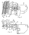
- the top wire 40 and the bottom wire 42 are provided with one or more elements, each having transverse, adjustable fins 44, which in the FIGS. 2 and 3 are shown.
- the present invention relates to an actuator for adjusting the fins in the elements of the cleaning.
- the fins 44 are mounted in a frame 45 which is supported by the screen box 38. It will open FIG. 3 in that each of the fins 44 is provided with a crankshaft 46 that is curved to form a crank arm 48.
- Each crank arm 48 is disposed in a slot 50 of an axial adjustment rod 52.
- the adjustment mechanism includes an actuator 56 which is secured to the frame 45 and has a linear or longitudinally movable output member 58.
- the dispensing element 58 has a threaded punch 60 which is secured to a support 62 by a nut.
- the holder 62 is rigidly connected to the adjusting rod 52.
- the output member 58 moves, as shown by the arrow 64, the adjustment rod 52 also moves, causing the crank arms 46 to rotate to change the angular position of the louvers 44.
- a Rotation of the fins 44 changes the gap "G" between adjacent fins 44.
- the internal components of the actuator 56 are more detailed in FIG FIG. 4 shown, wherein the housing of the actuator 56 is not shown.
- the actuator 56 includes a powered motor 66 having a rotatable output shaft 68 that drives a gear 70.
- the engine is an electric motor.
- Other types of motors may be used, such as hydraulic, pneumatic, etc.
- a speed reduction gear train 72 couples the output of the motor 66 to the rotatable input shaft 74 of a linear actuator 76. As the input shaft 74 rotates, internal screw threads in the linear actuator 76 cause it to rotate the non-rotatably fixed in the housing 56 of the actuator 56 output member 58 moves linearly or longitudinally, as shown by the arrow 64.
- the input shaft 74 is formed with a hexagonal, square or similar, non-round shaped piece 78 that extends out of the housing of the actuator 56, as in FIGS FIGS. 2 and 3 shown.
- the fitting 78 may be used to turn the input shaft 74 with a key when required in the event of a failure of the electric drive system or damage to the speed reduction gear train 72.
- the control system for the adjustment mechanism is shown schematically in FIG FIG. 5 shown.
- Two actuators 56 are shown, one for the louvered 44 element of the top wire 40 and another for the cleaning element of the bottom wire 42. If the top wire 40 and bottom wire 42 have more than one element, an actuator 56 is provided for each element.
- the control system operates via a CAN-based controller network to allow the operator to make adjustments while traveling from the cab 34.
- a microprocessor-based controller 90 is located at the core of the control system and receives inputs from each of the sensors 80 and 84. Another input to the controller 90 is from the operator input device 92.
- the operator of the combine 10 uses the operator input device 92 to make adjustments to the slat position.
- a second input device (not shown) may be provided on the side of the combine 10 to make adjustments when the combine harvester 10 is not harvesting.
- the outputs of the controller 90 include signals to the actuators 56 to operate the respective motors 66 to open or close the fins 44.
- a display 94 displays to the operator a number or the like corresponding to the size of the gap "G".
- the elements of the top wire 40 and the bottom wire 42 are each independently adjustable by a separate switch on the operator input device 92. If the upper wire 40 and / or the lower wire 42 have multiple elements, the control system may be configured to set the elements separately or together.
- the control system further includes a first sensor 80 disposed along the length of the output member 58.
- a magnet 82 causes the sensor 80 to generate a signal when the output member 58 is in a known position. In the known position, the gap "G" between adjacent lamellae is known. The gap "G" in the known position is measured at the factory and stored in the memory of the control system.
- a second sensor 84 is positioned adjacent a magnet ring 86 on the input shaft 74 of the linear actuator 76. The sensor 84 generates a signal when ever one of the poles of the magnetic ring 86 passes the sensor 84.
- the output member 58 has moved a known distance corresponding to a known angular rotation of the crankshaft 46, causing the gap "G" between adjacent blades 44.
- the amount of movement from the output of the second sensor 84 is known.
- Both sensors 80, 84 are preferably contactless sensor types, such as Hall effect sensors. This improves the durability of the sensors and the overall function of the control system.
- the direction of rotation of the motor 66 which is likewise known to the controller 90, can also be taken into account in order to detect whether the lamellae 44 are respectively opened or closed.
- the motor 66 is controlled with a pulse width modulated control signal.
- the motor 66 may be modulated to slow speed when small adjustments to the louver position are made, and to high speed when large adjustments are made or the louvers 44 are fully opened to clean the elements.
- the operator input device 92 is shown with a pair of switches 96, 98, with a switch associated with the top wire and one with the bottom wire. Other switch arrangements can be used. Two-speed operation can be accomplished in a number of ways. Multiple switches on the input device can be used, with a number of low-speed switches, ie fine-tuning, and the other number of fast-setting switches used. Alternatively, a slow speed speed selector switch may be used along with a number of switches for the cleaning elements.
- Two-speed operation may be specified to the controller 90 using various schemes. For example, high speed operation may be activated after the switch has been depressed for a predetermined amount of time. Another scheme allows the operator to make low speed adjustments, and when using the actuator in a combine with automatic combine setting option 10, a high speed is used to adjust the settings between preset positions for different crops (corn, soybeans, wheat, etc.). ) and also to place the fins 44 in a wide open cleaning position. The idea of adjusting the slats 44 at different speeds comes independent inventive rank too.
- the actuator 56 drives the element directly without any gears or couplings between the output member 58 and the fins 44. This reduces dead play and hysteresis.
- the louvers 44 of the elements open or close immediately upon activation of the motor 66.
- the louver opening position sensing system is very accurate in both directions.
- the Hall effect sensors have no contacting parts so that they can survive in the shaking environment of the elements of the screen box 38.
- the first sensor 80 is calibrated to a known opening of the fins 44 in the factory and can then be used to track the accuracy of the feedback signal over time. This system can be recalibrated into this known position both automatically and on command by the operator via the operator input device 92.
- actuator 56 has been described in the context of the cleaning elements of a top wire 40 and a bottom wire 42, it can also be used with a pre-cleaning cleaning element provided with fins.
Landscapes
- Life Sciences & Earth Sciences (AREA)
- Environmental Sciences (AREA)
- Threshing Machine Elements (AREA)
- Combines (AREA)
- Guiding Agricultural Machines (AREA)
- Control Of Position Or Direction (AREA)
Applications Claiming Priority (2)
| Application Number | Priority Date | Filing Date | Title |
|---|---|---|---|
| US874540 | 2001-06-05 | ||
| US09/874,540 US6632136B2 (en) | 2001-06-05 | 2001-06-05 | Remote adjustment mechanism for a combine harvester cleaning element |
Publications (2)
| Publication Number | Publication Date |
|---|---|
| EP1264530A1 EP1264530A1 (de) | 2002-12-11 |
| EP1264530B1 true EP1264530B1 (de) | 2008-02-13 |
Family
ID=25364036
Family Applications (1)
| Application Number | Title | Priority Date | Filing Date |
|---|---|---|---|
| EP02100487A Expired - Lifetime EP1264530B1 (de) | 2001-06-05 | 2002-05-14 | Einstelleinrichtung eines Reinigungselements eines Mähdreschers |
Country Status (7)
| Country | Link |
|---|---|
| US (1) | US6632136B2 (da) |
| EP (1) | EP1264530B1 (da) |
| AR (1) | AR036038A1 (da) |
| BR (1) | BR0202099A (da) |
| CA (1) | CA2382644C (da) |
| DE (1) | DE50211657D1 (da) |
| DK (1) | DK1264530T3 (da) |
Families Citing this family (32)
| Publication number | Priority date | Publication date | Assignee | Title |
|---|---|---|---|---|
| DE10120957C2 (de) * | 2001-04-27 | 2003-04-24 | Ford New Holland Nv | Vorrichtung zur Verstellung der Sieböffnungsweite an Mähdreschern |
| US6761630B1 (en) * | 2003-02-10 | 2004-07-13 | Case, Llc | Method of operation of a sieve adjustment control system for an agricultural combine |
| US7000411B2 (en) * | 2003-04-30 | 2006-02-21 | Lg Electronics Inc. | Apparatus for controlling outdoor unit's louver blades and its method |
| DE102005027741A1 (de) * | 2005-06-16 | 2007-01-18 | Deere & Company, Moline | Sieb für eine Reinigungseinrichtung eines Mähdreschers |
| US7306513B2 (en) * | 2005-11-30 | 2007-12-11 | Deere & Company | Leveling by over-compensation |
| US7371162B2 (en) * | 2006-04-24 | 2008-05-13 | Cnh America Llc | Sieve adjustment mechanism for an agricultural combine |
| US20080004092A1 (en) * | 2006-06-30 | 2008-01-03 | Deere & Company, A Delaware Corporation | Remote sieve or chaffer adjustment |
| US7497775B1 (en) | 2007-08-28 | 2009-03-03 | Cnh America Llc | Rear accessible sieve retainer |
| US7946908B2 (en) * | 2008-07-14 | 2011-05-24 | Deere & Company | Flexible louver opening adjustment mechanism for a pivoting combine harvester cleaning element |
| CA2687185C (en) * | 2009-11-30 | 2014-01-21 | Norman Van Brabant | Grain loss sampling device |
| FR2958911B1 (fr) * | 2010-04-19 | 2012-04-27 | Snecma | Procede et systeme de surveillance du niveau d'huile contenue dans un reservoir d'un moteur d'aeronef |
| DE102010017687A1 (de) * | 2010-07-01 | 2012-01-05 | Claas Selbstfahrende Erntemaschinen Gmbh | Verfahren zur Einstellung zumindest eines Arbeitsorganes einer selbstfahrenden Erntemaschine |
| US8118649B1 (en) * | 2010-09-01 | 2012-02-21 | Cnh America Llc | Grain distribution sensor and control |
| DE102011007511A1 (de) | 2011-04-15 | 2012-10-18 | Deere & Company | Verfahren zur Einstellung einer Reinigungseinrichtung eines Mähdreschers und Reinigungseinrichtung |
| DE102011017620B4 (de) | 2011-04-27 | 2024-11-14 | Deere & Company | Reinigungseinrichtung eines Mähdreschers |
| DE102011052282A1 (de) * | 2011-07-29 | 2013-01-31 | Claas Selbstfahrende Erntemaschinen Gmbh | Reinigungssensor zur Steuerung der Erntegut- und Gebläsedruckverteilung |
| DE102011085977A1 (de) * | 2011-11-09 | 2013-05-16 | Deere & Company | Sieb für eine Reinigungseinrichtung eines Mähdreschers |
| US8622792B1 (en) * | 2012-11-26 | 2014-01-07 | Cnh America Llc | Rack and pinion sieve adjustment mechanism |
| US8821229B2 (en) | 2012-12-06 | 2014-09-02 | Cnh Industrial America Llc | Grain cleaning system for an agricultural combine |
| CN103125203B (zh) * | 2013-03-11 | 2015-04-08 | 四川伊俊农业机械制造有限公司 | 油菜、稻麦联合收割机 |
| US9526211B2 (en) * | 2014-02-28 | 2016-12-27 | Cnh Industrial America Llc | System and method of controlling airflow characteristics in an agricultural harvester |
| US9699971B2 (en) * | 2014-08-20 | 2017-07-11 | Pape′ Machinery, Inc. | Modified sieve |
| BR102016017197B1 (pt) | 2015-07-23 | 2021-08-24 | Cnh Industrial America Llc | Conjunto de peneira e colheitadeira agrícola |
| US10619462B2 (en) | 2016-06-18 | 2020-04-14 | Encline Artificial Lift Technologies LLC | Compressor for gas lift operations, and method for injecting a compressible gas mixture |
| US10045488B2 (en) * | 2016-08-01 | 2018-08-14 | Tribine Industries Llc | Bonus sieves and tailings return for an articulated agricultural harvesting combine |
| US10179511B2 (en) * | 2017-02-16 | 2019-01-15 | Deere & Company | Harvester electrical energy generation |
| US10238040B2 (en) * | 2017-04-06 | 2019-03-26 | Deere & Company | Harvester louver rotation |
| US10856469B2 (en) * | 2017-08-22 | 2020-12-08 | Hcc, Inc. | High strength sieve |
| US11765995B2 (en) * | 2017-09-18 | 2023-09-26 | Hcc, Inc. | Louver position sensing system for a sieve and chaffer of a combine harvester |
| US11369060B2 (en) * | 2018-02-19 | 2022-06-28 | Cnh Industrial America Llc | Removable auger trough |
| US10959380B2 (en) * | 2019-03-12 | 2021-03-30 | Cnh Industrial America Llc | Sieve for an agricultural harvester with adjustable louvers and associated adjustment assembly |
| US11533853B2 (en) * | 2019-09-12 | 2022-12-27 | Cnh Industrial America Llc | Agricultural vehicle with automatic motor-driven component calibration |
Family Cites Families (22)
| Publication number | Priority date | Publication date | Assignee | Title |
|---|---|---|---|---|
| US2253296A (en) | 1938-11-21 | 1941-08-19 | Hart Carter Co | Screen for threshing machines |
| US3472378A (en) | 1968-01-22 | 1969-10-14 | Case Co J I | Remote adjustment for combine sieve |
| DE7145564U (de) | 1971-12-03 | 1973-01-25 | Deere & Co | Reinigungsvorrichtung fuer maehdrescher |
| FR2416636A1 (fr) * | 1978-02-08 | 1979-09-07 | Sperry Rand Nv | Moissonneusebatteuse |
| US4466231A (en) | 1982-08-30 | 1984-08-21 | Sperry Corporation | Automatic sieve and chaffer adjustment in a combine harvester |
| US4502493A (en) | 1983-12-12 | 1985-03-05 | Hart-Carter Company | Infinite adjustment means for sieve and chaffer slats |
| US4712568A (en) | 1986-03-10 | 1987-12-15 | New Holland Inc. | Combine sieve adjustment mechanism |
| US4770190A (en) | 1987-05-15 | 1988-09-13 | Deere & Company | Cleaning shoe screen for an agricultural combine having readily replaceable louvers |
| US4897072A (en) | 1988-06-17 | 1990-01-30 | Harlan Bestland | Apparatus for adjusting the sieve of a combine harvester |
| US5338257A (en) * | 1992-05-29 | 1994-08-16 | Probe Adventures, Inc. | Combine sieve distributor apparatus |
| AU658066B2 (en) | 1992-09-10 | 1995-03-30 | Deere & Company | Neural network based control system |
| US5441826A (en) * | 1993-04-28 | 1995-08-15 | Sanyo Electric Co., Ltd. | Hydrogen-absorbing alloy electrode |
| DE69324672T2 (de) | 1993-06-14 | 1999-09-09 | New Holland Belgium N.V. | Anzeigevorrichtung für den eingestellten Lamellenwinkel in einer Erntemaschine |
| CA2145889A1 (en) | 1994-05-19 | 1995-11-20 | Mark Leonard Pearson | Cleaning shoe adjustment mechanism |
| AT401596B (de) | 1994-05-27 | 1996-10-25 | Wintersteiger Gmbh & Co | Siebvorrichtung für einen mähdrescher, insbesondere für einen versuchsfeldmähdrescher |
| US5525108A (en) * | 1994-08-02 | 1996-06-11 | Case Corporation | Cleaning system for an agricultural combine |
| GB2293080A (en) | 1994-09-17 | 1996-03-20 | New Holland Belguim Nv | Grain cleaner for combine harvester |
| CA2214867C (en) * | 1997-09-08 | 2001-03-13 | Pembina Colony Ltd. | Remote adjustment of a sieve of a combine harvester |
| US5984777A (en) * | 1998-02-12 | 1999-11-16 | Kuchar; George J. | Remote combine sieve adjuster |
| DE19931844A1 (de) | 1999-07-09 | 2001-01-11 | Claas Selbstfahr Erntemasch | Einrichtung zur Verstellung der Sieböffnungsweite an Mähdreschern |
| CA2298195A1 (en) | 1999-07-16 | 2001-01-16 | Deere & Company | Cleaning shoe adjustment mechanism for a harvester |
| DE10030262A1 (de) | 2000-06-20 | 2002-01-31 | Deere & Co | Reinigungseinrichtung |
-
2001
- 2001-06-05 US US09/874,540 patent/US6632136B2/en not_active Expired - Lifetime
-
2002
- 2002-04-19 CA CA002382644A patent/CA2382644C/en not_active Expired - Fee Related
- 2002-05-14 DK DK02100487T patent/DK1264530T3/da active
- 2002-05-14 EP EP02100487A patent/EP1264530B1/de not_active Expired - Lifetime
- 2002-05-14 DE DE50211657T patent/DE50211657D1/de not_active Expired - Lifetime
- 2002-05-30 AR ARP020102016A patent/AR036038A1/es active IP Right Grant
- 2002-06-04 BR BR0202099-8A patent/BR0202099A/pt not_active Application Discontinuation
Also Published As
| Publication number | Publication date |
|---|---|
| BR0202099A (pt) | 2003-04-22 |
| DE50211657D1 (de) | 2008-03-27 |
| DK1264530T3 (da) | 2008-06-16 |
| US6632136B2 (en) | 2003-10-14 |
| EP1264530A1 (de) | 2002-12-11 |
| AR036038A1 (es) | 2004-08-04 |
| CA2382644C (en) | 2005-12-20 |
| US20020183103A1 (en) | 2002-12-05 |
| CA2382644A1 (en) | 2002-12-05 |
Similar Documents
| Publication | Publication Date | Title |
|---|---|---|
| EP1264530B1 (de) | Einstelleinrichtung eines Reinigungselements eines Mähdreschers | |
| EP1238580B1 (de) | Sieb für einen Mähdrescher | |
| EP2510777B1 (de) | Verfahren zur Einstellung einer Reinigungseinrichtung eines Mähdreschers und Reinigungseinrichtung | |
| EP1068792B1 (de) | Einrichtung zur Verstellung der Sieböffnungsweite an Mähdreschern | |
| EP1704767B1 (de) | Verfahren zur Ermittlung eines Ziel-Einstellwertes | |
| DE3788569T2 (de) | Reinigungsvorrichtung für Mähdrescher. | |
| EP3180974B1 (de) | Verfahren für den betrieb eines mähdreschers | |
| EP2220925B1 (de) | Landwirtschaftliches Arbeitsfahrzeug und Anzeigeeinheit dafür | |
| EP0728409B1 (de) | Verfahren zur automatischen Regelung wenigstens eines Abschnitts der Gutbearbeitung in einer Erntemaschine | |
| DE3218832C2 (de) | Mähdrescher | |
| DE69324672T2 (de) | Anzeigevorrichtung für den eingestellten Lamellenwinkel in einer Erntemaschine | |
| DE2903910C2 (da) | ||
| DE602004003300T2 (de) | Benutzerschnittstelle und Steuerung für eine Haspelzinkenanordnung | |
| EP1731017A1 (de) | Verfahren zur Steuerung einer Erntemaschine | |
| EP1166617B1 (de) | Reinigungseinrichtung | |
| DE102020110342A1 (de) | Kühlsystem-Lufteinlass mit einem justierbaren Luftschlitz | |
| EP1068793B1 (de) | Sieb eines Mähdreschers | |
| EP1325834A1 (de) | Bordcomputersystem für ein Arbeitsfahrzeug | |
| EP0131693A1 (de) | Erntemaschine mit einem automatisch steuerbaren beweglichen, das Erntegut ausstossenden Stutzen | |
| EP3622800B1 (de) | Landwirtschaftliche erntemaschine | |
| DE102020204859A1 (de) | Erntesteuerungssystem mit messerbalken-lasterfassung | |
| DE102018212075A1 (de) | Mähdrescher mit einem Schrägförderer mit aktorisch verstellbarer, unterer Umlenkwalze | |
| DE2411153A1 (de) | Einrichtung zum messen von einflussgroessen fuer die regelung der arbeitsorgane von erntemaschinen, insbesondere maehdrescher | |
| EP3794932B1 (de) | Verschwenkvorrichtung zur gleichmässigen verteilung eines gutes auf einem förder- und reinigungsorgan | |
| DE102018215730A1 (de) | Lamellenpositionserfassungssystem für ein Sieb und einen Spreusichter eines Mähdreschers |
Legal Events
| Date | Code | Title | Description |
|---|---|---|---|
| PUAI | Public reference made under article 153(3) epc to a published international application that has entered the european phase |
Free format text: ORIGINAL CODE: 0009012 |
|
| AK | Designated contracting states |
Kind code of ref document: A1 Designated state(s): AT BE CH CY DE DK ES FI FR GB GR IE IT LI LU MC NL PT SE TR |
|
| AX | Request for extension of the european patent |
Free format text: AL;LT;LV;MK;RO;SI |
|
| 17P | Request for examination filed |
Effective date: 20030611 |
|
| AKX | Designation fees paid |
Designated state(s): BE DE DK FR IT |
|
| 17Q | First examination report despatched |
Effective date: 20060809 |
|
| 17Q | First examination report despatched |
Effective date: 20060809 |
|
| GRAP | Despatch of communication of intention to grant a patent |
Free format text: ORIGINAL CODE: EPIDOSNIGR1 |
|
| GRAS | Grant fee paid |
Free format text: ORIGINAL CODE: EPIDOSNIGR3 |
|
| GRAA | (expected) grant |
Free format text: ORIGINAL CODE: 0009210 |
|
| AK | Designated contracting states |
Kind code of ref document: B1 Designated state(s): BE DE DK FR IT |
|
| REF | Corresponds to: |
Ref document number: 50211657 Country of ref document: DE Date of ref document: 20080327 Kind code of ref document: P |
|
| REG | Reference to a national code |
Ref country code: DK Ref legal event code: T3 |
|
| ET | Fr: translation filed | ||
| PLBE | No opposition filed within time limit |
Free format text: ORIGINAL CODE: 0009261 |
|
| STAA | Information on the status of an ep patent application or granted ep patent |
Free format text: STATUS: NO OPPOSITION FILED WITHIN TIME LIMIT |
|
| 26N | No opposition filed |
Effective date: 20081114 |
|
| PGFP | Annual fee paid to national office [announced via postgrant information from national office to epo] |
Ref country code: IT Payment date: 20140526 Year of fee payment: 13 Ref country code: FR Payment date: 20140519 Year of fee payment: 13 |
|
| PG25 | Lapsed in a contracting state [announced via postgrant information from national office to epo] |
Ref country code: IT Free format text: LAPSE BECAUSE OF NON-PAYMENT OF DUE FEES Effective date: 20150514 |
|
| REG | Reference to a national code |
Ref country code: FR Ref legal event code: ST Effective date: 20160129 |
|
| PG25 | Lapsed in a contracting state [announced via postgrant information from national office to epo] |
Ref country code: FR Free format text: LAPSE BECAUSE OF NON-PAYMENT OF DUE FEES Effective date: 20150601 |
|
| PGFP | Annual fee paid to national office [announced via postgrant information from national office to epo] |
Ref country code: DK Payment date: 20190530 Year of fee payment: 18 |
|
| PGFP | Annual fee paid to national office [announced via postgrant information from national office to epo] |
Ref country code: BE Payment date: 20190527 Year of fee payment: 18 |
|
| REG | Reference to a national code |
Ref country code: DK Ref legal event code: EBP Effective date: 20200531 |
|
| REG | Reference to a national code |
Ref country code: BE Ref legal event code: MM Effective date: 20200531 |
|
| PG25 | Lapsed in a contracting state [announced via postgrant information from national office to epo] |
Ref country code: DK Free format text: LAPSE BECAUSE OF NON-PAYMENT OF DUE FEES Effective date: 20200531 |
|
| PG25 | Lapsed in a contracting state [announced via postgrant information from national office to epo] |
Ref country code: BE Free format text: LAPSE BECAUSE OF NON-PAYMENT OF DUE FEES Effective date: 20200531 |
|
| PGFP | Annual fee paid to national office [announced via postgrant information from national office to epo] |
Ref country code: DE Payment date: 20210421 Year of fee payment: 20 |
|
| REG | Reference to a national code |
Ref country code: DE Ref legal event code: R071 Ref document number: 50211657 Country of ref document: DE |