EP1263191A2 - Appareil électronique portable - Google Patents
Appareil électronique portable Download PDFInfo
- Publication number
- EP1263191A2 EP1263191A2 EP02252695A EP02252695A EP1263191A2 EP 1263191 A2 EP1263191 A2 EP 1263191A2 EP 02252695 A EP02252695 A EP 02252695A EP 02252695 A EP02252695 A EP 02252695A EP 1263191 A2 EP1263191 A2 EP 1263191A2
- Authority
- EP
- European Patent Office
- Prior art keywords
- display panel
- cover
- user
- display
- display panels
- Prior art date
- Legal status (The legal status is an assumption and is not a legal conclusion. Google has not performed a legal analysis and makes no representation as to the accuracy of the status listed.)
- Granted
Links
Images

Classifications
-
- G—PHYSICS
- G06—COMPUTING; CALCULATING OR COUNTING
- G06F—ELECTRIC DIGITAL DATA PROCESSING
- G06F1/00—Details not covered by groups G06F3/00 - G06F13/00 and G06F21/00
- G06F1/16—Constructional details or arrangements
- G06F1/1613—Constructional details or arrangements for portable computers
- G06F1/1633—Constructional details or arrangements of portable computers not specific to the type of enclosures covered by groups G06F1/1615 - G06F1/1626
- G06F1/1637—Details related to the display arrangement, including those related to the mounting of the display in the housing
- G06F1/1647—Details related to the display arrangement, including those related to the mounting of the display in the housing including at least an additional display
- G06F1/165—Details related to the display arrangement, including those related to the mounting of the display in the housing including at least an additional display the additional display being small, e.g. for presenting status information
-
- G—PHYSICS
- G06—COMPUTING; CALCULATING OR COUNTING
- G06F—ELECTRIC DIGITAL DATA PROCESSING
- G06F1/00—Details not covered by groups G06F3/00 - G06F13/00 and G06F21/00
- G06F1/16—Constructional details or arrangements
- G06F1/1613—Constructional details or arrangements for portable computers
- G06F1/1626—Constructional details or arrangements for portable computers with a single-body enclosure integrating a flat display, e.g. Personal Digital Assistants [PDAs]
-
- G—PHYSICS
- G06—COMPUTING; CALCULATING OR COUNTING
- G06F—ELECTRIC DIGITAL DATA PROCESSING
- G06F1/00—Details not covered by groups G06F3/00 - G06F13/00 and G06F21/00
- G06F1/16—Constructional details or arrangements
- G06F1/1613—Constructional details or arrangements for portable computers
- G06F1/1633—Constructional details or arrangements of portable computers not specific to the type of enclosures covered by groups G06F1/1615 - G06F1/1626
- G06F1/1675—Miscellaneous details related to the relative movement between the different enclosures or enclosure parts
- G06F1/1679—Miscellaneous details related to the relative movement between the different enclosures or enclosure parts for locking or maintaining the movable parts of the enclosure in a fixed position, e.g. latching mechanism at the edge of the display in a laptop or for the screen protective cover of a PDA
-
- G—PHYSICS
- G06—COMPUTING; CALCULATING OR COUNTING
- G06F—ELECTRIC DIGITAL DATA PROCESSING
- G06F2200/00—Indexing scheme relating to G06F1/04 - G06F1/32
- G06F2200/16—Indexing scheme relating to G06F1/16 - G06F1/18
- G06F2200/163—Indexing scheme relating to constructional details of the computer
- G06F2200/1634—Integrated protective display lid, e.g. for touch-sensitive display in handheld computer
-
- H—ELECTRICITY
- H04—ELECTRIC COMMUNICATION TECHNIQUE
- H04M—TELEPHONIC COMMUNICATION
- H04M1/00—Substation equipment, e.g. for use by subscribers
- H04M1/02—Constructional features of telephone sets
- H04M1/0202—Portable telephone sets, e.g. cordless phones, mobile phones or bar type handsets
- H04M1/0206—Portable telephones comprising a plurality of mechanically joined movable body parts, e.g. hinged housings
- H04M1/0208—Portable telephones comprising a plurality of mechanically joined movable body parts, e.g. hinged housings characterized by the relative motions of the body parts
- H04M1/0214—Foldable telephones, i.e. with body parts pivoting to an open position around an axis parallel to the plane they define in closed position
-
- H—ELECTRICITY
- H04—ELECTRIC COMMUNICATION TECHNIQUE
- H04M—TELEPHONIC COMMUNICATION
- H04M2250/00—Details of telephonic subscriber devices
- H04M2250/16—Details of telephonic subscriber devices including more than one display unit
-
- H—ELECTRICITY
- H04—ELECTRIC COMMUNICATION TECHNIQUE
- H04M—TELEPHONIC COMMUNICATION
- H04M2250/00—Details of telephonic subscriber devices
- H04M2250/22—Details of telephonic subscriber devices including a touch pad, a touch sensor or a touch detector
Definitions
- the present invention pertains to a portable device, for example a hybrid portable device utilizing separate display panels pre-assigned to respective operation modes for displaying associated information and selected cross-operation information.
- the device typically provides mobile communication and PDA features.
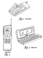
- FIG. 1, FIG. 2 and FIG. 3 Two current embodiments adopted by manufacturers are shown in FIG. 1, FIG. 2 and FIG. 3.
- FIG. 1 illustrates a portable device, which includes a single display panel and a movable cover.
- the cover is designed to move between a closed position and an open position. In the closed position, the cover overlays a large proportion of the display panel, exposing only a small portion of the display panel for viewing by a user.
- the small visible portion typically displays information pertaining to mobile communication, such as signal strength, battery level and incoming call alert.
- the cover In an open position, the cover is flipped to reveal the entire display panel for viewing lengthy information such as electronic mail messages, calendar entries and task lists.
- Information pertaining to mobile communication that was previously displayed in a portrait orientation is reoriented and rearranged on the display for viewing in a landscape orientation.
- the user has to instantly familiarize himself with the different content locations. Thus he is likely to be confused by the abrupt change in orientation and frustrated by the inconvenience of relocating information and reorienting his visual perspective.
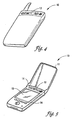
- FIG. 2 and FIG.3 illustrate a second portable device, which includes two display panels on different faces of a cover-like plane. Both display panels are separately powered.
- the smaller display panel in FIG. 2 is powered up when the mobile phone mode is active.
- the larger display panel in FIG. 3 is powered up when the PDA mode is active. In this way, usage of battery power is conserved as compared to the first portable device.
- the second device has a lower power-consumption advantage over the first device
- the second device has other drawbacks.
- the cover-like plane is opened so that the user can view the larger display panel arranged on an inner side of the cover.
- the information pertaining to mobile communication previously displayed on the smaller screen is now displayed on a left vertical sidebar on the larger display panel.
- the effective display area is reduced, which translates into inefficient use of precious display area.
- the user has to make a mental effort to locate such information by consciously identifying the associated status (or menu) bar embedded within the display area.
- the user has to close the cover to answer the call in a conventional manner and thereafter open the cover again to continue with using PDA functions.
- the user has to reorient his visual perspective when switching between the two display panels.
- the present invention seeks to overcome the various drawbacks of user presentations in existing devices for improving users' experience and to provide a new user presentation for use in portable information devices.
- the preferred embodiment provides a hybrid or multifunction portable device utilizing separate display panels pre-assigned to different operation modes, such as, mobile communication and PDA functions, for displaying associated information and selected cross-operation information.
- the device includes at least two display panels, a movable cover pivoting about one end of the device for moving between a closed and an open position.
- a closed position only a first display panel is visible to a user.
- the open position both the first display panel and a second display panel are visible to the user.
- the movable cover may also be readily detached from the hybrid device when necessary without interrupting the operation of the device. Alternatively, the device may work without the cover.
- the preferred user presentation has the following advantages. By having each display panel powering up only when its designated mode of operation is active, power usage is made more efficient. Furthermore, having separate display panels for pre-assigned operation modes emulates familiar presentation of conventional single-use device, i.e., a mobile phone and a PDA, and allows location of information to be generally fixed. A user, especially a new user, no longer has to make a mental effort to consciously locate such information.
- the display panels by displaying information associated to its operation mode, allow a user to immediately access (or view) the respective display panel without added mental effort.
- the display panels are arranged to allow a user to view both display panels simultaneously, or to view only one display panel in collaboration with the cover, when desired by the user. An example of this arrangement is to place both display panels on a same surface of the device.
- the preferred embodiment is particularly advantageous for conveying both a distinct phone personality (when the cover is in a closed position), and a phone-and-PDA personality (when the cover is in an open position or when without the cover). In so doing, a new user is quickly eased into using the device with minimal readapting. More importantly, it can eliminate the need for a user to readapt to abrupt changes in user presentation when switching between display panels or operation modes.
- a portable device 10 which can incorporate the described embodimentstypically provides mobile communication functions and PDA functions.
- the portable device 10 includes a first display panel and a larger second display panel 13 arranged on a same face of the device 10.
- the first display panel is typically a LCD (Liquid Crystal Display);
- the second display panel 13 is a LCD screen with an overlaying transparent touch-sensitive panel.
- the device 10 also includes a protective movable cover 11 for overlaying upon the second display panel 13.
- the protective cover 11 is attached to a longitudinal end of the device 10 for allowing the protective cover 11 to pivotally move between a closed position (illustrated by FIG.4) and an open position (illustrated by FIG.5). When the cover 11 is not required, it can be readily removed by detaching the cover 11 from the device 10.
- the device 10 may also include at least one input area.
- a first input area includes two input buttons 14 arranged on a top face of the device 10 proximate to the first display panel 12; a second input area includes four input buttons 14 arranged on the top face and proximate to the second display panel 13.
- Each input area is typically assigned to an operation mode for activating functions associated with the mode, or displaying information on a display panel corresponding to its operation mode, or both.
- the device 10 may also include a serial port, a USB or a connection port arranged on a bottom panel of the device 10 for information transfer and synchronization.
- Other typical elements in the device 10 are an antenna (hidden or visible to a user), a printed circuit board containing electronic circuits for operating the device 10, speakers, microphone, battery and other elements typical of such devices.
- Both the first 12 and the second 13 display panels are, for example, arranged on a same surface of the device 10 such that a user is able to simultaneously view information from both the display panels in a same orientation.
- the first display panel 12 is dedicated to display information content arising from using a first operational mode, e.g., mobile communication. It may display information such as signal strength, battery level, current network operator and personalized greetings as appropriate or preset by a user.
- the second display panel 13, which is substantially larger, is dedicated to display information content from using a second operational mode, e.g., PDA. Examples of such information include calendar application information, electronic mail messages, word processing documents and web pages.
- both panels are driven by separate power regulators and LCD controllers.
- the power regulator and LCD controller of each display panel may be driven by a single power source, e.g., a rechargeable battery, or by a separate corresponding power source.
- a cover 11 for this device 10 is movable at least between an open position and a closed position for selectively exposing or overlaying the second display panel 13 from a user.
- the cover 11 is typically opaque so that when it moves at least between an open position and a closed position, it selectively conceals (or overlays), or reveals (or exposes) the second display panel 13 to a user.
- the cover 11 is substantially of the same size as the device 10. Hence in the closed position, the cover 11 effectively conceals the second display panel 13, and forms an enclosed volume between the viewing surface of the second display panel 13 and the inner side of the cover 11 for protecting the surface of the second display panel 13 from dust and abrasive particles.
- the cover 11 may include a locking mechanism for firmly securing the cover 11 to the device 10 during a closed position so that the cover 11 does not inadvertently flip open.
- the locking mechanism may take any form, such as, having locking studs along a side of the cover 11 to engage with receiving hollows on the device 10, or the like.
- the cover 11 also includes an attachment means, which removably attaches the cover 11 to the device 10 and allows the cover 11 to move at least between two positions.
- An example of such removable attachment means is a hinge system as illustrated in FIG.6.
- the hinge system also includes a detent mechanism 21 which locks the cover 11 in a certain position to prevent the cover 11 from inadvertently closing or opening.
- the cover 11 also includes a cut-away portion (or opening) on one side, suitably dimensioned to reveal at least the first display panel 12 when the cover 11 is in a closed position.
- the cut-away portion may alternatively be suitably dimensioned to also reveal input buttons 14 for operating a first operation mode.
- the cut-away portion may be replaced by other viewing means such as a transparent surface.
- the transparent surface may also take the form of a magnifying material.
- FIG.4 and FIG.5 illustrate the cover 11 to be substantially of the same size as the device 10, it is not to be so limited.
- the cover 11 should preferably be sized to overlay at least the second display panel 13 during a closed position.
- FIG. 4 illustrates the portable device 10 with the cover 11 in a closed position, where the arrangement of the cover 11 and the first display panel 12 conveys a distinct phone personality.
- the closed position is typically used when the device 10 is not in use or when a mobile communication mode is enabled.
- the device 10 When the mobile communication mode is enabled, the device 10 is ready to receive and transmit calls of any form, including voice, data, or the like. Accordingly, the first display panel 12 is powered up and information content associated with mobile communication features is displayed on the first display panel 12 for viewing by a user. In this closed position, the protective cover 11 sufficiently conceals at least the second display panel 13 such that it is not visible to a user. The protective cover 11 may alternatively conceal the second display panel 13 and its corresponding input area such that both are not visible to the user (see FIG. 4). The protective cover 11, however, reveals the entire first display panel 12 to a user through a viewing means, such as, a cut-away portion along one end of the cover 11.
- a viewing means such as, a cut-away portion along one end of the cover 11.
- a user may recall phone numbers from the device's 10 memory. However, if the number is not available, the user may input the phone number by accessing an on-screen keypad in the second display panel 13. In so doing, the second display panel 13 is powered. The number inputted is shown in the second display panel 13 and also displayed in the first display panel 12. In this respect, the second display panel 13 is able to display cross-operation information in a manner defined by a manufacturer, while not compromising the phone personality. Alternatively, the user may access a keypad of keyboard that may be connected to the device.
- FIG.5 illustrates the device 10 with the cover 11 in an open position, where the arrangement of the display panels conveys a distinct phone-and-PDA personality.
- the open position is typically used when a user activates at least the PDA operation mode.
- the second display panel 13 is powered up and information content associated with PDA mode is displayed on the second display panel 13.
- the protective cover 11 is sufficiently lifted to fully reveal both the first and the second display panels to the user.
- a detent mechanism 21 is implemented at the hinge to prevent the cover 11 from inadvertently closing while the user is accessing the second display panel 13.
- the cover 11 As the cover 11 is removably attached to the device 10, the cover 11 may be removed without affecting the normal operation of the device 10.
- the cover 11 may be made of a transparent material such that even as the cover 11 overlays the second display panel 13, the display panel 13 is visible, though not accessible, to a user. Hence, a cover like such selectively overlays or exposes the second display panel 13. Regardless of the degree of transparency of the cover 11, the cover is generally movable to selectively overlay or expose at least a second display panel.
- the first display panel 12 is consistently visible to a user and both display panels are simultaneously visible to a user when the second display panel 13 is exposed.
- a second embodiment of the present invention is shown in FIG.7, which works in a similar manner.
- a protective cover 11a for this embodiment is a sliding cover 11a that extends from one side of the second display panel 13 to another either in a vertical direction or a lateral direction.
- the sliding cover 11a sufficiently overlays at least the second display panel 13 during a closed position. In an open position, the second display panel 13 is revealed and visible to a user.
- the sliding cover 11a overlays upon the second display panel 13 with a minute gap between the bottom surface of the cover 11a and a top (or viewable) surface of the second display panel 13. This is to prevent the sliding cover 11a from contacting the top surface and scratching it.
- the sliding cover 11a may overlay in direct contact with the top surface of the second display panel 13 if at least the bottom surface of the sliding cover 11a is made of a non-abrasive (or non-scratch) material, or according to a manufacturer's preference.
- guiding rails may be provided to guide the sliding movement.
- the sliding cover 11a may be stored discretely and hidden from a user's view. This may be done by having a rotating rail within the device 10 to receive the sliding cover 11a and wrapping it around the rail while the cover 11a slides to an open position.
- a rotating rail within the device 10 to receive the sliding cover 11a and wrapping it around the rail while the cover 11a slides to an open position.
- a cover for use in the described embodiments is a retractable cover slidably mounted to the device 10, as described in US Patent No. 5,530,234.
- the retractable cover may be modified for use by having a viewing means, or having the retractable cover made of a transparent material, as described earlier.
- both the first and the second display panels are arranged on a same surface of the hybrid device 10, it may not be so limited.
- the display panels may be arranged on different surfaces of the device 10. However, for consistent display location of information and good user presentation, both display panels need to be simultaneously visible to a user when the cover is in an open position. Similarly, the number of display panels may not be limited.
Landscapes
- Engineering & Computer Science (AREA)
- Theoretical Computer Science (AREA)
- Computer Hardware Design (AREA)
- Human Computer Interaction (AREA)
- Physics & Mathematics (AREA)
- General Engineering & Computer Science (AREA)
- General Physics & Mathematics (AREA)
- Telephone Set Structure (AREA)
- Devices For Indicating Variable Information By Combining Individual Elements (AREA)
- Telephone Function (AREA)
- Mobile Radio Communication Systems (AREA)
Applications Claiming Priority (2)
| Application Number | Priority Date | Filing Date | Title |
|---|---|---|---|
| US867837 | 2001-05-30 | ||
| US09/867,837 US20020183099A1 (en) | 2001-05-30 | 2001-05-30 | Multiple display panels for different modes of operation for conveying personality |
Publications (3)
| Publication Number | Publication Date |
|---|---|
| EP1263191A2 true EP1263191A2 (fr) | 2002-12-04 |
| EP1263191A3 EP1263191A3 (fr) | 2003-09-17 |
| EP1263191B1 EP1263191B1 (fr) | 2005-10-26 |
Family
ID=25350553
Family Applications (1)
| Application Number | Title | Priority Date | Filing Date |
|---|---|---|---|
| EP02252695A Expired - Lifetime EP1263191B1 (fr) | 2001-05-30 | 2002-04-16 | Appareil électronique portable |
Country Status (4)
| Country | Link |
|---|---|
| US (1) | US20020183099A1 (fr) |
| EP (1) | EP1263191B1 (fr) |
| JP (1) | JP2003066874A (fr) |
| DE (1) | DE60206832D1 (fr) |
Cited By (6)
| Publication number | Priority date | Publication date | Assignee | Title |
|---|---|---|---|---|
| EP1458171A1 (fr) * | 2003-02-04 | 2004-09-15 | Samsung Electronics Co., Ltd. | Terminal mobile intégré et méthode de contrôle d'un afficheur extérieur |
| WO2005050424A2 (fr) * | 2003-11-24 | 2005-06-02 | Siemens Aktiengesellschaft | Affichage recouvrable pour appareils utilises en technique d'automation |
| EP1542118A1 (fr) * | 2003-12-10 | 2005-06-15 | Samsung Electronics Co., Ltd. | Terminal mobile hybride et procédé de commande de celui-ci |
| EP1701520A1 (fr) * | 2005-03-09 | 2006-09-13 | LG Electronics Inc. | Téléphone mobile pliable évitant un secouement nuisant à la charnière |
| WO2007036321A1 (fr) * | 2005-09-27 | 2007-04-05 | Huf Hülsbeck & Fürst Gmbh & Co. Kg | Dispositif de fermeture telecommande pour vehicule |
| WO2014074963A3 (fr) * | 2012-11-09 | 2014-10-02 | Microsoft Corporation | Dispositifs mobiles à plusieurs dispositifs d'affichage |
Families Citing this family (16)
| Publication number | Priority date | Publication date | Assignee | Title |
|---|---|---|---|---|
| JP3726892B2 (ja) * | 2001-10-15 | 2005-12-14 | ソニー株式会社 | 携帯端末装置およびその表示制御プログラム |
| KR20030033880A (ko) * | 2001-10-25 | 2003-05-01 | 엘지전자 주식회사 | Lcd가 장착된 힌지장치를 갖는 듀얼-폴더형 이동 단말기 |
| US20030104850A1 (en) * | 2001-12-04 | 2003-06-05 | Cheng-Shing Lai | PDA with a protective cover for its display panel |
| AUPS107202A0 (en) | 2002-03-13 | 2002-04-11 | K W Dinn Holdings Pty Limited | Improved device interface |
| US9697264B2 (en) | 2002-08-20 | 2017-07-04 | Kannuu Pty. Ltd. | Process and apparatus for selecting an item from a database |
| US20050253773A1 (en) * | 2002-09-25 | 2005-11-17 | Kanetaka Sekiguchi | Display |
| JP2004240236A (ja) * | 2003-02-07 | 2004-08-26 | Hitachi Ltd | 表示装置 |
| US7155266B2 (en) * | 2004-04-21 | 2006-12-26 | Nokia Corporation | Hinge for fold phone |
| KR100737887B1 (ko) * | 2003-05-20 | 2007-07-10 | 삼성전자주식회사 | 구동회로, 이를 갖는 평판표시장치 및 이의 구동방법 |
| TWI244057B (en) * | 2004-03-01 | 2005-11-21 | Au Optronics Corp | Dual display module |
| US7812786B2 (en) * | 2005-01-18 | 2010-10-12 | Nokia Corporation | User interface for different displays |
| CA2618775C (fr) | 2005-08-12 | 2014-09-30 | Kannuu Pty Ltd | Procede ameliore et appareil pour choisir un article dans une base de donnees |
| CA2717265A1 (fr) * | 2007-03-07 | 2008-09-12 | Kannuu Pty Ltd | Procede, systeme et appareil de saisie de texte sur un dispositif informatique |
| US8599105B2 (en) * | 2010-07-02 | 2013-12-03 | Nokia Corporation | Method and apparatus for implementing a multiple display mode |
| US20160378137A1 (en) * | 2015-06-26 | 2016-12-29 | Intel Corporation | Electronic device with combinable image input devices |
| WO2017052590A1 (fr) | 2015-09-25 | 2017-03-30 | Intel Corporation | Charnière de dispositif électronique |
Citations (6)
| Publication number | Priority date | Publication date | Assignee | Title |
|---|---|---|---|---|
| EP0776140A1 (fr) * | 1995-11-24 | 1997-05-28 | Nokia Mobile Phones Ltd. | Dispositif de communication à usage double |
| EP0886204A1 (fr) * | 1997-06-20 | 1998-12-23 | Compaq Computer Corporation | Afficheur en temps réel d'indicateur de niveau de charge d'une batterie |
| EP0898405A2 (fr) * | 1997-08-22 | 1999-02-24 | Hitachi, Ltd. | Dispositif terminal de communication d'information |
| US6014141A (en) * | 1997-03-25 | 2000-01-11 | Micron Electronics, Inc. | Method and apparatus for selectively displaying a parameter in a separate status panel |
| GB2343324A (en) * | 1998-11-02 | 2000-05-03 | Samsung Electronics Co Ltd | Folder-type mobile phone provided with a double-panel lcd |
| US6125286A (en) * | 1997-06-05 | 2000-09-26 | Motorola, Inc. | Communication device having multiple displays and method of operating the same |
Family Cites Families (7)
| Publication number | Priority date | Publication date | Assignee | Title |
|---|---|---|---|---|
| US6347218B1 (en) * | 1996-02-28 | 2002-02-12 | Nokia Mobile Phones Limited | Electronic device with housing supplement |
| FI109732B (fi) * | 1998-06-02 | 2002-09-30 | Nokia Corp | Elektroniikkalaite ja ohjauselin |
| US6434403B1 (en) * | 1999-02-19 | 2002-08-13 | Bodycom, Inc. | Personal digital assistant with wireless telephone |
| JP4298054B2 (ja) * | 1999-04-23 | 2009-07-15 | パナソニック株式会社 | 携帯形無線装置 |
| US6434404B1 (en) * | 1999-05-06 | 2002-08-13 | Qualcomm, Incorporated | Detection of flip closure state of a flip phone |
| IL146262A (en) * | 2000-03-14 | 2007-02-11 | Samsung Electronics Co Ltd | Personal digital assistant / integrated telephone device |
| US7016704B2 (en) * | 2001-04-02 | 2006-03-21 | Move Mobile Systems, Inc. | Coordinating images displayed on devices with two or more displays |
-
2001
- 2001-05-30 US US09/867,837 patent/US20020183099A1/en not_active Abandoned
-
2002
- 2002-04-16 EP EP02252695A patent/EP1263191B1/fr not_active Expired - Lifetime
- 2002-04-16 DE DE60206832T patent/DE60206832D1/de not_active Expired - Lifetime
- 2002-05-28 JP JP2002153596A patent/JP2003066874A/ja active Pending
Patent Citations (6)
| Publication number | Priority date | Publication date | Assignee | Title |
|---|---|---|---|---|
| EP0776140A1 (fr) * | 1995-11-24 | 1997-05-28 | Nokia Mobile Phones Ltd. | Dispositif de communication à usage double |
| US6014141A (en) * | 1997-03-25 | 2000-01-11 | Micron Electronics, Inc. | Method and apparatus for selectively displaying a parameter in a separate status panel |
| US6125286A (en) * | 1997-06-05 | 2000-09-26 | Motorola, Inc. | Communication device having multiple displays and method of operating the same |
| EP0886204A1 (fr) * | 1997-06-20 | 1998-12-23 | Compaq Computer Corporation | Afficheur en temps réel d'indicateur de niveau de charge d'une batterie |
| EP0898405A2 (fr) * | 1997-08-22 | 1999-02-24 | Hitachi, Ltd. | Dispositif terminal de communication d'information |
| GB2343324A (en) * | 1998-11-02 | 2000-05-03 | Samsung Electronics Co Ltd | Folder-type mobile phone provided with a double-panel lcd |
Cited By (10)
| Publication number | Priority date | Publication date | Assignee | Title |
|---|---|---|---|---|
| EP1458171A1 (fr) * | 2003-02-04 | 2004-09-15 | Samsung Electronics Co., Ltd. | Terminal mobile intégré et méthode de contrôle d'un afficheur extérieur |
| US7366549B2 (en) | 2003-02-04 | 2008-04-29 | Samsung Electronics Co., Ltd. | Integrated mobile terminal device and method for controlling external display unit |
| WO2005050424A2 (fr) * | 2003-11-24 | 2005-06-02 | Siemens Aktiengesellschaft | Affichage recouvrable pour appareils utilises en technique d'automation |
| WO2005050424A3 (fr) * | 2003-11-24 | 2005-10-27 | Siemens Ag | Affichage recouvrable pour appareils utilises en technique d'automation |
| EP1542118A1 (fr) * | 2003-12-10 | 2005-06-15 | Samsung Electronics Co., Ltd. | Terminal mobile hybride et procédé de commande de celui-ci |
| CN100346659C (zh) * | 2003-12-10 | 2007-10-31 | 三星电子株式会社 | 混合移动终端及其控制方法 |
| EP1701520A1 (fr) * | 2005-03-09 | 2006-09-13 | LG Electronics Inc. | Téléphone mobile pliable évitant un secouement nuisant à la charnière |
| US7616975B2 (en) | 2005-03-09 | 2009-11-10 | Lg Electronics Inc. | Folder type mobile phone |
| WO2007036321A1 (fr) * | 2005-09-27 | 2007-04-05 | Huf Hülsbeck & Fürst Gmbh & Co. Kg | Dispositif de fermeture telecommande pour vehicule |
| WO2014074963A3 (fr) * | 2012-11-09 | 2014-10-02 | Microsoft Corporation | Dispositifs mobiles à plusieurs dispositifs d'affichage |
Also Published As
| Publication number | Publication date |
|---|---|
| DE60206832D1 (de) | 2005-12-01 |
| US20020183099A1 (en) | 2002-12-05 |
| EP1263191A3 (fr) | 2003-09-17 |
| JP2003066874A (ja) | 2003-03-05 |
| EP1263191B1 (fr) | 2005-10-26 |
Similar Documents
| Publication | Publication Date | Title |
|---|---|---|
| EP1263191B1 (fr) | Appareil électronique portable | |
| EP0933908B1 (fr) | Appareil électronique pliable portatif | |
| USRE40204E1 (en) | Portable electronic terminal apparatus having a plurality of displays | |
| US7983628B2 (en) | Cellular telephone and personal digital assistant | |
| EP1635550B1 (fr) | Dispositif d'affichage pour opération multitâche d'un terminal mobile et procédé correspondant | |
| US7016182B2 (en) | Physical configuration of a hand-held electronic communication device | |
| EP1570333B1 (fr) | Dispositif de traitement de donnees comprenant un ecran ajustable et des dispositifs d'entree a orientations multiples | |
| US20080167081A1 (en) | Keyless touch-screen cellular telephone | |
| US20090017875A1 (en) | Cellular telephone and personal digital assistant | |
| US20020068614A1 (en) | Personal communication device having a built in projection display | |
| US7321789B2 (en) | Folding information processor | |
| US20090181733A1 (en) | Portable communication device having a multi-axis hinge assembly | |
| KR20090126142A (ko) | 이동단말기 및 그 디스플레이 제어 방법 | |
| JPH09247250A (ja) | 無線装置 | |
| JP3501710B2 (ja) | 携帯電話機 | |
| KR100374771B1 (ko) | 휴대형 전화기 및 휴대형 정보 단말기가 복합된 휴대형복합 무선 단말기 | |
| KR101922007B1 (ko) | 휴대 전자기기 | |
| JP2005260673A (ja) | 情報処理装置及び表示管理方法 | |
| KR101023131B1 (ko) | 양면 표시장치를 갖는 휴대용 이동통신 단말기 | |
| JP2003319036A (ja) | 移動通信装置 | |
| JP2002369252A (ja) | 携帯電話端末およびその表示制御方法 | |
| EP1432216A1 (fr) | Ecran pour un dispositif de communication mobile | |
| KR200230378Y1 (ko) | 이동통신기기의 이중덮개 | |
| KR20050035455A (ko) | 서브 디스플레이 장치를 적용한 슬라이드형이동통신단말기. | |
| JP2005026818A (ja) | 携帯電子機器 |
Legal Events
| Date | Code | Title | Description |
|---|---|---|---|
| PUAI | Public reference made under article 153(3) epc to a published international application that has entered the european phase |
Free format text: ORIGINAL CODE: 0009012 |
|
| AK | Designated contracting states |
Kind code of ref document: A2 Designated state(s): AT BE CH CY DE DK ES FI FR GB GR IE IT LI LU MC NL PT SE TR |
|
| AX | Request for extension of the european patent |
Free format text: AL;LT;LV;MK;RO;SI |
|
| PUAL | Search report despatched |
Free format text: ORIGINAL CODE: 0009013 |
|
| AK | Designated contracting states |
Kind code of ref document: A3 Designated state(s): AT BE CH CY DE DK ES FI FR GB GR IE IT LI LU MC NL PT SE TR |
|
| AX | Request for extension of the european patent |
Extension state: AL LT LV MK RO SI |
|
| 17P | Request for examination filed |
Effective date: 20040209 |
|
| 17Q | First examination report despatched |
Effective date: 20040311 |
|
| AKX | Designation fees paid |
Designated state(s): DE FR GB |
|
| GRAP | Despatch of communication of intention to grant a patent |
Free format text: ORIGINAL CODE: EPIDOSNIGR1 |
|
| GRAS | Grant fee paid |
Free format text: ORIGINAL CODE: EPIDOSNIGR3 |
|
| GRAA | (expected) grant |
Free format text: ORIGINAL CODE: 0009210 |
|
| AK | Designated contracting states |
Kind code of ref document: B1 Designated state(s): DE FR GB |
|
| REG | Reference to a national code |
Ref country code: GB Ref legal event code: FG4D |
|
| REF | Corresponds to: |
Ref document number: 60206832 Country of ref document: DE Date of ref document: 20051201 Kind code of ref document: P |
|
| PG25 | Lapsed in a contracting state [announced via postgrant information from national office to epo] |
Ref country code: DE Free format text: LAPSE BECAUSE OF FAILURE TO SUBMIT A TRANSLATION OF THE DESCRIPTION OR TO PAY THE FEE WITHIN THE PRESCRIBED TIME-LIMIT Effective date: 20060127 |
|
| PGFP | Annual fee paid to national office [announced via postgrant information from national office to epo] |
Ref country code: FR Payment date: 20060417 Year of fee payment: 5 |
|
| PGFP | Annual fee paid to national office [announced via postgrant information from national office to epo] |
Ref country code: DE Payment date: 20060531 Year of fee payment: 5 |
|
| PLBE | No opposition filed within time limit |
Free format text: ORIGINAL CODE: 0009261 |
|
| STAA | Information on the status of an ep patent application or granted ep patent |
Free format text: STATUS: NO OPPOSITION FILED WITHIN TIME LIMIT |
|
| 26N | No opposition filed |
Effective date: 20060727 |
|
| EN | Fr: translation not filed | ||
| PG25 | Lapsed in a contracting state [announced via postgrant information from national office to epo] |
Ref country code: FR Free format text: LAPSE BECAUSE OF FAILURE TO SUBMIT A TRANSLATION OF THE DESCRIPTION OR TO PAY THE FEE WITHIN THE PRESCRIBED TIME-LIMIT Effective date: 20061215 |
|
| PGFP | Annual fee paid to national office [announced via postgrant information from national office to epo] |
Ref country code: GB Payment date: 20100401 Year of fee payment: 9 |
|
| GBPC | Gb: european patent ceased through non-payment of renewal fee |
Effective date: 20110416 |
|
| PG25 | Lapsed in a contracting state [announced via postgrant information from national office to epo] |
Ref country code: GB Free format text: LAPSE BECAUSE OF NON-PAYMENT OF DUE FEES Effective date: 20110416 |