EP1263082A1 - Device for sending and receiving electromagnetic waves - Google Patents
Device for sending and receiving electromagnetic waves Download PDFInfo
- Publication number
- EP1263082A1 EP1263082A1 EP02011738A EP02011738A EP1263082A1 EP 1263082 A1 EP1263082 A1 EP 1263082A1 EP 02011738 A EP02011738 A EP 02011738A EP 02011738 A EP02011738 A EP 02011738A EP 1263082 A1 EP1263082 A1 EP 1263082A1
- Authority
- EP
- European Patent Office
- Prior art keywords
- card
- sending
- antenna
- axis
- receiving
- Prior art date
- Legal status (The legal status is an assumption and is not a legal conclusion. Google has not performed a legal analysis and makes no representation as to the accuracy of the status listed.)
- Withdrawn
Links
Images

Classifications
-
- H—ELECTRICITY
- H01—ELECTRIC ELEMENTS
- H01Q—ANTENNAS, i.e. RADIO AERIALS
- H01Q3/00—Arrangements for changing or varying the orientation or the shape of the directional pattern of the waves radiated from an antenna or antenna system
- H01Q3/02—Arrangements for changing or varying the orientation or the shape of the directional pattern of the waves radiated from an antenna or antenna system using mechanical movement of antenna or antenna system as a whole
- H01Q3/08—Arrangements for changing or varying the orientation or the shape of the directional pattern of the waves radiated from an antenna or antenna system using mechanical movement of antenna or antenna system as a whole for varying two co-ordinates of the orientation
-
- H—ELECTRICITY
- H01—ELECTRIC ELEMENTS
- H01Q—ANTENNAS, i.e. RADIO AERIALS
- H01Q1/00—Details of, or arrangements associated with, antennas
- H01Q1/12—Supports; Mounting means
- H01Q1/125—Means for positioning
-
- H—ELECTRICITY
- H01—ELECTRIC ELEMENTS
- H01Q—ANTENNAS, i.e. RADIO AERIALS
- H01Q19/00—Combinations of primary active antenna elements and units with secondary devices, e.g. with quasi-optical devices, for giving the antenna a desired directional characteristic
- H01Q19/10—Combinations of primary active antenna elements and units with secondary devices, e.g. with quasi-optical devices, for giving the antenna a desired directional characteristic using reflecting surfaces
- H01Q19/18—Combinations of primary active antenna elements and units with secondary devices, e.g. with quasi-optical devices, for giving the antenna a desired directional characteristic using reflecting surfaces having two or more spaced reflecting surfaces
- H01Q19/19—Combinations of primary active antenna elements and units with secondary devices, e.g. with quasi-optical devices, for giving the antenna a desired directional characteristic using reflecting surfaces having two or more spaced reflecting surfaces comprising one main concave reflecting surface associated with an auxiliary reflecting surface
Definitions
- the present invention relates to devices for sending and receiving electromagnetic waves.
- the patent application WO 99/35711 describes such a device which includes a sending chip and a receiving chip, each perpendicular to a waveguide formed by an end cap and by a rod which defines a common sending and receiving direction of the device.
- the sending chip comprises a power amplifier which delivers an electrical signal to the waveguide and thus generates the electromagnetic wave to be sent out.
- the sending chip is generally called an SSPA (Solid State Power Amplifier: semiconductor power amplifier) electronics card.
- the receiving chip includes a low-noise amplifier which receives, as input, the signal output from the waveguide.
- the receiving chip is thus generally called an LNA (Low Noise Amplifier) electronics card.
- the inventors have taken into consideration the thermal and electromagnetic problems due to the presence of these two chips or electronics cards in the device.
- a device for sending and receiving electromagnetic waves along an antenna axis comprising a sending electronics card defining a first length and a receiving electronics card defining a second length, in which the first length extends essentially from the antenna axis, in which the second length extends essentially from the antenna axis, and in which the first length and the second length define between them an angle of at least 90° in projection in a plane perpendicular to the antenna axis.
- the above angle should be understood as an angle between two straight-line segments which have a common extremity (antenna axis) and which can therefore vary in a general way between 0° (segments coincident) and 180° (segments aligned but opposed with respect to the antenna axis).
- a device for sending and receiving electromagnetic waves including an antenna, a sending electronics card, a receiving electronics card, in which the sending electronics card possesses a first extremity opposite an antenna-connection extremity, in which the receiving electronics card possesses a second extremity opposite an antenna-connection extremity and in which the first extremity and the second extremity are separated by an angle of at least 90° with respect to the antenna in projection in a plane perpendicular to the axis of the antenna.
- the antenna is, for example, connected to each of the electronics cards in the region of a primary source of the antenna, such as a waveguide.
- the primary source may also be of another type, for example with spirals or with printed elements.
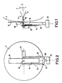
- the device represented in Figure 1 comprises an antenna consisting of an external reflector 2 of generally parabolic shape, of an internal reflector 4 and of a waveguide 6 (which plays the role of primary source for the antenna) including a horn 8 of frustoconical shape and a tube 10 of cylindrical shape.
- the antenna defines an antenna axis ⁇ which is the axis common to the reflectors 2, 4 and to the waveguide 6.
- an electromagnetic wave incident along the direction of the antenna axis ⁇ is concentrated onto the internal reflector 4 by the external reflector 2, then reflected by the internal reflector 4 towards the horn 8 where it propagates in the tube 10.
- an electromagnetic wave induced in the tube 10 is sent out along the antenna axis ⁇ by the external reflector 2.
- the device comprises a receiving electronics card 12 (LNA card) of generally rectangular shape, which carries a low-noise amplifier 18 (represented symbolically in Figure 1). In an end region, in the direction of its length, the LNA card 12 is in contact with the tube 10 of the waveguide 6 in order thus to form the electrical connection between the waveguide 6 and the low-noise amplifier 18.
- the LNA card 12 is perpendicular to the waveguide 6 and thus to the antenna axis ⁇ .
- the device also comprises a sending electronics card 14 (SSPA card) of generally rectangular shape which carries a power amplifier 20 (represented symbolically in Figure 1).
- SSPA card Send Electronics card
- the SSPA card is perpendicular to the waveguide 6 and thus to the antenna axis ⁇ .
- the face of the SSPA card 14 opposite to that which carries the power amplifier 20 constitutes the earth plane of the SSPA card 14 and carries a radiator 16 in order to facilitate the removal of the heat generated by the SSPA card 14 (up to a few tens of watts).
- the assembly consisting of the antenna and the LNA 12 and SSPA 14 cards is movable in rotation on an arm 22 by means of a first motor 24.
- the arm 22 In a plane perpendicular to the antenna axis ⁇ , the arm 22 has the general shape of a "U", the two parallel branches 26 of which extend parallel to the length of the SSPA card 14 from a base 28.
- the axis of the first motor 24 extends along the length of the SSPA card 14 in the region of the respective extremities of the branches 26 which are opposite the base 28.
- the first motor 24 allows adjustment of the antenna axis ⁇ in elevation.
- the arm 22 for its part is movable in rotation by means of a second motor 30 with axis perpendicular to the antenna axis ⁇ and to the axis of the first motor 24.
- the axis of the second motor 30 is therefore parallel to the length of the SSPA card 14.
- the second motor 30 allows adjustment of the antenna axis ⁇ in azimuth.
- the device can track a satellite in its trajectory and thus communicate with this satellite as long as it is in the field of view of the device. (This is necessary especially in the case of satellites in low orbit, or Low Earth Orbit (LEO) satellites which are mobile in the terrestrial reference system.)
- LEO Low Earth Orbit
- the width of the SSPA card 14 is less than the distance which separates the branches 26 of the arm 22, such that, upon rotation of the first motor 24, the SSPA card 14 can pass freely between the branches 26 of the arm 22.
- the radiator 16 is situated on the face of the SSPA card 14 which is turned towards the arm 22 and the reflector 2.
- the low-noise amplifier 18 is situated on the face of the LNA card 12 opposite the reflector 2. Furthermore, the length of the LNA card 12 extends mainly at 180° from the length of the SSPA card 14 with respect to the tube 10 of the waveguide 6 (in projection in a plane perpendicular to the antenna axis ⁇ ). Put another way, the LNA card 12 extends away from the SSPA card 14 with respect to the waveguide 6 and therefore with respect to the antenna axis ⁇ .
- this configuration promotes thermal dissipation, especially in the region of the radiator 16, and reduces the temperature and thus the noise in the region of the LNA card 12. Furthermore, it makes the design of the LNA 12 and SSPA 14 cards more flexible, since it reduces the thermal or electromagnetic interactions between the two cards, interactions which usually require specific precautions.
- Figure 3 represents a variant embodiment of the invention.
- the numerical references used in Figure 1 and 2 are retained in Figure 3.
- the arm 22 has the shape of an "L" consisting of a base 28 and of a branch 26.
- the branch 26 carries the first motor 24, the axis of which is perpendicular to the branch 26 and to the antenna axis ⁇ (as in the example of Figure 1 and 2).
- the length of the LNA card 12 extends parallel to the branch 26 (and therefore perpendicularly to the axis of the first motor 24 and to the antenna axis ⁇ ) in a way which is similar to the example of Figure 1 and 2.
- the length of the SSPA card 14 extends parallel to the axis of the first motor 24.
- the LNA 12 and SSPA 14 cards are therefore each situated in a plane perpendicular to the waveguide and therefore to the antenna axis ⁇ as described above; however, according to the variant, the length of the LNA card 12 and the length of the SSPA card 14 form an angle of 90° in projection in a plane perpendicular to the antenna axis ⁇ .
- the invention is not limited to the embodiments described above.
- the invention has been described in the context of a sending and receiving device with a movable antenna axis, for a low-orbit (LEO) satellite, for example, it naturally relates also to the devices with a fixed antenna axis, for example for a geostationary satellite.
- LEO low-orbit
Landscapes
- Variable-Direction Aerials And Aerial Arrays (AREA)
- Transmitters (AREA)
- Support Of Aerials (AREA)
- Transceivers (AREA)
Applications Claiming Priority (2)
| Application Number | Priority Date | Filing Date | Title |
|---|---|---|---|
| FR0107233 | 2001-06-01 | ||
| FR0107233A FR2825539A1 (fr) | 2001-06-01 | 2001-06-01 | Dispositif pour l'emission et la reception d'ondes electro-magnetiques |
Publications (1)
| Publication Number | Publication Date |
|---|---|
| EP1263082A1 true EP1263082A1 (en) | 2002-12-04 |
Family
ID=8863889
Family Applications (1)
| Application Number | Title | Priority Date | Filing Date |
|---|---|---|---|
| EP02011738A Withdrawn EP1263082A1 (en) | 2001-06-01 | 2002-05-27 | Device for sending and receiving electromagnetic waves |
Country Status (6)
| Country | Link |
|---|---|
| US (1) | US6690334B2 (enExample) |
| EP (1) | EP1263082A1 (enExample) |
| JP (1) | JP2003060524A (enExample) |
| CN (1) | CN1306656C (enExample) |
| FR (1) | FR2825539A1 (enExample) |
| MX (1) | MXPA02005389A (enExample) |
Cited By (2)
| Publication number | Priority date | Publication date | Assignee | Title |
|---|---|---|---|---|
| WO2003083995A1 (en) * | 2002-03-27 | 2003-10-09 | The Boeing Company | Dual reflector antenna with waveguide diplexer and omt mounted on back of main reflector |
| EP1596466A1 (de) * | 2004-05-14 | 2005-11-16 | RR ELEKTRONISCHE GERÄTE GmbH & Co. | Empfangsantenne mit Nachführvorrichtung |
Families Citing this family (3)
| Publication number | Priority date | Publication date | Assignee | Title |
|---|---|---|---|---|
| KR101038352B1 (ko) * | 2007-07-30 | 2011-06-01 | 가부시키가이샤 무라타 세이사쿠쇼 | 전자파 측정장치 |
| FR2920595B1 (fr) * | 2007-09-05 | 2011-03-04 | Eversat | Antenne satellite d'emission et station portative |
| KR20150058960A (ko) * | 2013-11-21 | 2015-05-29 | 한국전자통신연구원 | 무선랜 단말 위치 측위 장치 및 방법 |
Citations (3)
| Publication number | Priority date | Publication date | Assignee | Title |
|---|---|---|---|---|
| US4901369A (en) * | 1985-02-22 | 1990-02-13 | Nec Corporation | Microwave transmitter/receiver apparatus |
| US4924239A (en) * | 1989-02-28 | 1990-05-08 | The United States Of America As Represented By The Secretary Of The Air Force | Antenna mounting apparatus |
| EP0855092A1 (en) * | 1995-10-13 | 1998-07-29 | NIELSEN, Peter | Method and system for communicating electromagnetic signals |
Family Cites Families (5)
| Publication number | Priority date | Publication date | Assignee | Title |
|---|---|---|---|---|
| JPS5534550A (en) * | 1978-09-02 | 1980-03-11 | Nec Corp | Car-mounting antenna device |
| DE3345529C1 (de) * | 1983-12-16 | 1999-09-02 | Diehl Stiftung & Co | Zielsuchende Munition mit vor ihrer Gefechtsladung-Einlage angeordnetem Sensor-Wandler |
| SE507288C2 (sv) * | 1997-06-13 | 1998-05-11 | Trulstech Innovation Kb | Anordning omfattande antennreflektor och sändar/mottagarhorn kombinerade till en kompakt antennenhet |
| FR2777117B1 (fr) * | 1998-04-06 | 2000-04-28 | Alsthom Cge Alcatel | Lentille spherique focalisante multicouches |
| US6198452B1 (en) * | 1999-05-07 | 2001-03-06 | Rockwell Collins, Inc. | Antenna configuration |
-
2001
- 2001-06-01 FR FR0107233A patent/FR2825539A1/fr active Pending
-
2002
- 2002-05-22 CN CNB021202923A patent/CN1306656C/zh not_active Expired - Fee Related
- 2002-05-27 EP EP02011738A patent/EP1263082A1/en not_active Withdrawn
- 2002-05-29 JP JP2002155834A patent/JP2003060524A/ja active Pending
- 2002-05-29 US US10/157,572 patent/US6690334B2/en not_active Expired - Fee Related
- 2002-05-30 MX MXPA02005389A patent/MXPA02005389A/es active IP Right Grant
Patent Citations (3)
| Publication number | Priority date | Publication date | Assignee | Title |
|---|---|---|---|---|
| US4901369A (en) * | 1985-02-22 | 1990-02-13 | Nec Corporation | Microwave transmitter/receiver apparatus |
| US4924239A (en) * | 1989-02-28 | 1990-05-08 | The United States Of America As Represented By The Secretary Of The Air Force | Antenna mounting apparatus |
| EP0855092A1 (en) * | 1995-10-13 | 1998-07-29 | NIELSEN, Peter | Method and system for communicating electromagnetic signals |
Cited By (2)
| Publication number | Priority date | Publication date | Assignee | Title |
|---|---|---|---|---|
| WO2003083995A1 (en) * | 2002-03-27 | 2003-10-09 | The Boeing Company | Dual reflector antenna with waveguide diplexer and omt mounted on back of main reflector |
| EP1596466A1 (de) * | 2004-05-14 | 2005-11-16 | RR ELEKTRONISCHE GERÄTE GmbH & Co. | Empfangsantenne mit Nachführvorrichtung |
Also Published As
| Publication number | Publication date |
|---|---|
| JP2003060524A (ja) | 2003-02-28 |
| CN1306656C (zh) | 2007-03-21 |
| US20020180653A1 (en) | 2002-12-05 |
| US6690334B2 (en) | 2004-02-10 |
| FR2825539A1 (fr) | 2002-12-06 |
| MXPA02005389A (es) | 2003-01-28 |
| CN1389956A (zh) | 2003-01-08 |
Similar Documents
| Publication | Publication Date | Title |
|---|---|---|
| US6975276B2 (en) | System and low-loss millimeter-wave cavity-backed antennas with dielectric and air cavities | |
| DK1278266T3 (da) | Lavprisantenne med höj ydelse til anvendelse i sende/modtagesatellitterminaler | |
| US6137171A (en) | Lightweight miniaturized integrated microsatellite employing advanced semiconductor processing and packaging technology | |
| EP0930669A2 (en) | Antenna for communicating with low earth orbit satellite | |
| JP2018518118A (ja) | 単一軸ジンバルを有するスーパー楕円アンテナ開口を使用した低コスト衛星間リンクのための統合アンテナおよびrfペイロード | |
| EP1076377A2 (en) | Satellite antenna pointing system | |
| US6690334B2 (en) | Devices for sending and receiving electromagnetic waves | |
| KR100272790B1 (ko) | 초고주파 안테나 시스템 | |
| WO1992016981A1 (en) | Dual band integrated lnb feedhorn system | |
| US6642905B2 (en) | Thermal-locate 5W(V) and 5W(H) SSPA's on back of reflector(s) | |
| US6677908B2 (en) | Multimedia aircraft antenna | |
| US6429824B2 (en) | Low profile, broadband, dual mode, modified notch antenna | |
| JP2002204124A (ja) | 主反射鏡ジンバルを備えた側方給電形式のオフセット・カセグレン・アンテナ | |
| US11319092B2 (en) | Space vehicle, launcher and stack of space vehicles | |
| KR20020092187A (ko) | 전자기파의 송출 및 수신용 디바이스 | |
| US6052559A (en) | Thermoelectrically cooled low noise amplifier and method | |
| JP3261933B2 (ja) | Gps受信装置 | |
| JP2011024024A (ja) | アンテナ装置 | |
| US7403076B1 (en) | High frequency quasi optical power source capable of solid state implementation | |
| US5351061A (en) | Antenna with parabolic reflector | |
| JPS62102629A (ja) | アンテナ装置 | |
| DE3581340D1 (de) | Kabelanschlusseinrichtung fuer symmetrische antenne. | |
| JPH0797727B2 (ja) | 平面アレイアンテナ | |
| JPH07154122A (ja) | 衛星間通信用アンテナ装置 | |
| JPS6345904A (ja) | 反射鏡アンテナ |
Legal Events
| Date | Code | Title | Description |
|---|---|---|---|
| PUAI | Public reference made under article 153(3) epc to a published international application that has entered the european phase |
Free format text: ORIGINAL CODE: 0009012 |
|
| AK | Designated contracting states |
Kind code of ref document: A1 Designated state(s): AT BE CH CY DE DK ES FI FR GB GR IE IT LI LU MC NL PT SE TR |
|
| AX | Request for extension of the european patent |
Free format text: AL;LT;LV;MK;RO;SI |
|
| AKX | Designation fees paid | ||
| 17P | Request for examination filed |
Effective date: 20030526 |
|
| RBV | Designated contracting states (corrected) |
Designated state(s): AT BE CH CY DE DK ES FI FR GB GR IE IT LI LU MC NL PT SE TR |
|
| REG | Reference to a national code |
Ref country code: DE Ref legal event code: 8566 |
|
| RAP1 | Party data changed (applicant data changed or rights of an application transferred) |
Owner name: THOMSON LICENSING |
|
| 17Q | First examination report despatched |
Effective date: 20070326 |
|
| STAA | Information on the status of an ep patent application or granted ep patent |
Free format text: STATUS: THE APPLICATION IS DEEMED TO BE WITHDRAWN |
|
| 18D | Application deemed to be withdrawn |
Effective date: 20081113 |