EP1263003A2 - Preparation of a rare earth magnet alloy powder for a bonded magnet and rare earth bonded magnet therewith - Google Patents
Preparation of a rare earth magnet alloy powder for a bonded magnet and rare earth bonded magnet therewith Download PDFInfo
- Publication number
- EP1263003A2 EP1263003A2 EP02253685A EP02253685A EP1263003A2 EP 1263003 A2 EP1263003 A2 EP 1263003A2 EP 02253685 A EP02253685 A EP 02253685A EP 02253685 A EP02253685 A EP 02253685A EP 1263003 A2 EP1263003 A2 EP 1263003A2
- Authority
- EP
- European Patent Office
- Prior art keywords
- rare earth
- alloy
- bonded
- weight
- magnet
- Prior art date
- Legal status (The legal status is an assumption and is not a legal conclusion. Google has not performed a legal analysis and makes no representation as to the accuracy of the status listed.)
- Granted
Links
Images


Classifications
-
- H—ELECTRICITY
- H01—ELECTRIC ELEMENTS
- H01F—MAGNETS; INDUCTANCES; TRANSFORMERS; SELECTION OF MATERIALS FOR THEIR MAGNETIC PROPERTIES
- H01F1/00—Magnets or magnetic bodies characterised by the magnetic materials therefor; Selection of materials for their magnetic properties
- H01F1/01—Magnets or magnetic bodies characterised by the magnetic materials therefor; Selection of materials for their magnetic properties of inorganic materials
- H01F1/03—Magnets or magnetic bodies characterised by the magnetic materials therefor; Selection of materials for their magnetic properties of inorganic materials characterised by their coercivity
- H01F1/032—Magnets or magnetic bodies characterised by the magnetic materials therefor; Selection of materials for their magnetic properties of inorganic materials characterised by their coercivity of hard-magnetic materials
- H01F1/04—Magnets or magnetic bodies characterised by the magnetic materials therefor; Selection of materials for their magnetic properties of inorganic materials characterised by their coercivity of hard-magnetic materials metals or alloys
- H01F1/047—Alloys characterised by their composition
- H01F1/053—Alloys characterised by their composition containing rare earth metals
-
- H—ELECTRICITY
- H01—ELECTRIC ELEMENTS
- H01F—MAGNETS; INDUCTANCES; TRANSFORMERS; SELECTION OF MATERIALS FOR THEIR MAGNETIC PROPERTIES
- H01F1/00—Magnets or magnetic bodies characterised by the magnetic materials therefor; Selection of materials for their magnetic properties
- H01F1/01—Magnets or magnetic bodies characterised by the magnetic materials therefor; Selection of materials for their magnetic properties of inorganic materials
- H01F1/03—Magnets or magnetic bodies characterised by the magnetic materials therefor; Selection of materials for their magnetic properties of inorganic materials characterised by their coercivity
- H01F1/032—Magnets or magnetic bodies characterised by the magnetic materials therefor; Selection of materials for their magnetic properties of inorganic materials characterised by their coercivity of hard-magnetic materials
- H01F1/04—Magnets or magnetic bodies characterised by the magnetic materials therefor; Selection of materials for their magnetic properties of inorganic materials characterised by their coercivity of hard-magnetic materials metals or alloys
- H01F1/047—Alloys characterised by their composition
- H01F1/053—Alloys characterised by their composition containing rare earth metals
- H01F1/055—Alloys characterised by their composition containing rare earth metals and magnetic transition metals, e.g. SmCo5
- H01F1/0551—Alloys characterised by their composition containing rare earth metals and magnetic transition metals, e.g. SmCo5 in the form of particles, e.g. rapid quenched powders or ribbon flakes
-
- H—ELECTRICITY
- H01—ELECTRIC ELEMENTS
- H01F—MAGNETS; INDUCTANCES; TRANSFORMERS; SELECTION OF MATERIALS FOR THEIR MAGNETIC PROPERTIES
- H01F1/00—Magnets or magnetic bodies characterised by the magnetic materials therefor; Selection of materials for their magnetic properties
- H01F1/01—Magnets or magnetic bodies characterised by the magnetic materials therefor; Selection of materials for their magnetic properties of inorganic materials
- H01F1/03—Magnets or magnetic bodies characterised by the magnetic materials therefor; Selection of materials for their magnetic properties of inorganic materials characterised by their coercivity
- H01F1/032—Magnets or magnetic bodies characterised by the magnetic materials therefor; Selection of materials for their magnetic properties of inorganic materials characterised by their coercivity of hard-magnetic materials
- H01F1/04—Magnets or magnetic bodies characterised by the magnetic materials therefor; Selection of materials for their magnetic properties of inorganic materials characterised by their coercivity of hard-magnetic materials metals or alloys
- H01F1/047—Alloys characterised by their composition
- H01F1/053—Alloys characterised by their composition containing rare earth metals
- H01F1/055—Alloys characterised by their composition containing rare earth metals and magnetic transition metals, e.g. SmCo5
-
- H—ELECTRICITY
- H01—ELECTRIC ELEMENTS
- H01F—MAGNETS; INDUCTANCES; TRANSFORMERS; SELECTION OF MATERIALS FOR THEIR MAGNETIC PROPERTIES
- H01F1/00—Magnets or magnetic bodies characterised by the magnetic materials therefor; Selection of materials for their magnetic properties
- H01F1/01—Magnets or magnetic bodies characterised by the magnetic materials therefor; Selection of materials for their magnetic properties of inorganic materials
- H01F1/03—Magnets or magnetic bodies characterised by the magnetic materials therefor; Selection of materials for their magnetic properties of inorganic materials characterised by their coercivity
- H01F1/032—Magnets or magnetic bodies characterised by the magnetic materials therefor; Selection of materials for their magnetic properties of inorganic materials characterised by their coercivity of hard-magnetic materials
- H01F1/04—Magnets or magnetic bodies characterised by the magnetic materials therefor; Selection of materials for their magnetic properties of inorganic materials characterised by their coercivity of hard-magnetic materials metals or alloys
- H01F1/047—Alloys characterised by their composition
- H01F1/053—Alloys characterised by their composition containing rare earth metals
- H01F1/055—Alloys characterised by their composition containing rare earth metals and magnetic transition metals, e.g. SmCo5
- H01F1/0555—Alloys characterised by their composition containing rare earth metals and magnetic transition metals, e.g. SmCo5 pressed, sintered or bonded together
- H01F1/0558—Alloys characterised by their composition containing rare earth metals and magnetic transition metals, e.g. SmCo5 pressed, sintered or bonded together bonded together
-
- B—PERFORMING OPERATIONS; TRANSPORTING
- B22—CASTING; POWDER METALLURGY
- B22F—WORKING METALLIC POWDER; MANUFACTURE OF ARTICLES FROM METALLIC POWDER; MAKING METALLIC POWDER; APPARATUS OR DEVICES SPECIALLY ADAPTED FOR METALLIC POWDER
- B22F9/00—Making metallic powder or suspensions thereof
- B22F9/02—Making metallic powder or suspensions thereof using physical processes
- B22F9/04—Making metallic powder or suspensions thereof using physical processes starting from solid material, e.g. by crushing, grinding or milling
- B22F2009/041—Making metallic powder or suspensions thereof using physical processes starting from solid material, e.g. by crushing, grinding or milling by mechanical alloying, e.g. blending, milling
-
- B—PERFORMING OPERATIONS; TRANSPORTING
- B22—CASTING; POWDER METALLURGY
- B22F—WORKING METALLIC POWDER; MANUFACTURE OF ARTICLES FROM METALLIC POWDER; MAKING METALLIC POWDER; APPARATUS OR DEVICES SPECIALLY ADAPTED FOR METALLIC POWDER
- B22F2998/00—Supplementary information concerning processes or compositions relating to powder metallurgy
Definitions
- This invention relates to a method for preparing an alloy for bonded Sm 2 Co 17 base magnets and a bonded Sm 2 Co 17 base magnet composition comprising the alloy.
- Bonded Sm 2 Co 17 base magnet powder is traditionally prepared by milling an alloy ingot having a regulated composition to a particle size of about 1 to 10 microns, pressing and shaping the resulting powder in a magnetic field to form a powder compact, sintering the powder compact in an argon atmosphere at 1100 to 1300°C, and typically about 1200°C, for a time of 1 to 5 hours, followed by solution treatment.
- the solution-treated compact is subjected to aging treatment in which it is held at a temperature of 700 to 900°C, and typically about 800°C, for about 10 hours, then gradually cooled to 400°C or lower at a descending rate of -1.0°C/min.
- the sintered magnet is finally ground to a predetermined particle size.
- This powder metallurgy process requires a more number of steps and a longer time than the sintered magnet producing process, and has the drawbacks of increased cost and low production efficiency.
- bonded Sm 2 Co 17 base magnet powder is prepared by subjecting an alloy ingot having a regulated composition to solution treatment in an argon atmosphere at 1100 to 1300°C, and typically about 1200°C, followed by aging treatment in which it is held at a temperature of 700 to 900°C, and typically about 800°C, for about 10 hours, then gradually cooled to 400°C or lower at a rate of -1.0°C/min.
- the treated ingot is finally ground to a predetermined particle size.
- the bonded rare earth magnet-forming alloy powder obtained by this process has the advantage of low cost, as compared with the bonded rare earth magnet-forming alloy powder obtained by the powder metallurgy process (involving grinding the once sintered rare earth magnet).
- the bonded Sm 2 Co 17 base magnet powder obtained by this process is known to have magnetic properties which are affected by the crystalline state of the ingot following melting. Specifically, the bonded Sm 2 Co 17 base magnet powder obtained from an ingot whose crystalline state is predominantly composed of chill crystals and equiaxed crystals has poor magnetic properties, especially low coercivity, whereas the bonded Sm 2 Co 17 base magnet powder obtained from an ingot whose crystalline state is predominantly composed of columnar crystals has good magnetic properties, especially high coercivity (see JP-A 56-102533 and JP-A 7-57909).
- One solution to the above problem is a casting technique using a single roll, known as strip casting technique, which results in more than 90% by volume of columnar crystals (see JP-A 8-260083).
- the ingot produced by this casting technique has a microcrystalline structure and a uniform alloy structure free of segregation.
- anisotropic bonded rare earth magnets however, anisotropic bonded rare earth magnets having satisfactory magnetic properties cannot be manufactured unless all bonded rare earth magnet-forming powder particles are unidirectionally oriented. Since the ingot obtained by the strip casting technique has a microcrystalline structure, the bonded rare earth magnet-forming alloy must be ground into a fine powder or the ingot must be subjected to heat treatment and solution treatment to induce grain growth.
- An object of the invention is to provide new methods for preparing a bonded Sm 2 Co 17 base magnet-forming alloy, of good or improved magnetic properties.
- Other aspects are the novel alloy preparations obtained or obtainable by the new method, bonded magnets containing the alloy preparation blended with resin, and the method comprising the manufacture of the bonded magnetic compositions.
- the invention provides a method for preparing an alloy for bonded rare earth magnets, comprising the steps of melting an alloy consisting essentially of 20 to 30% by weight of R which is samarium or a mixture of at least two rare earth elements (inclusive of Y) containing at least 50% by weight of samarium, 10 to 45% by weight of iron, 1 to 10% by weight of copper, 0.5 to 5% by weight of zirconium, and the balance of cobalt; quenching the melt by a strip casting technique, to form a rare earth alloy strip containing at least 20% by volume of equiaxed crystals with a grain size of 1 to 200 ⁇ m and having a gage of 0.05 to 3 mm; heat treating the strip in a non-oxidizing atmosphere at 1000 to 1300°C for 0.5 to 20 hours; followed by aging treatment and grinding.
- R is samarium or a mixture of at least two rare earth elements (inclusive of Y) containing at least 50% by weight of samarium, 10 to
- the invention provides a method for preparing an alloy for bonded rare earth magnets, comprising the steps of melting an alloy of the same composition as above; quenching the melt from a melt temperature of 1250 to 1600°C by a strip casting technique; heat treating the resulting rare earth alloy in a non-oxidizing atmosphere at 1000 to 1300°C for 0.5 to 20 hours; followed by aging treatment and grinding.
- a further embodiment of the invention is a bonded rare earth magnet composition
- a bonded rare earth magnet composition comprising the bonded rare earth magnet-forming alloy obtained by either of the above methods and a resin, e.g. at 1 to 10% by weight.
- the present invention permits optimum solution treatment to be accomplished within a brief time.
- the use of the specific alloy allows the crystal grain size to grow up without such serious compositional shift.
- the sequence of solution treatment, aging treatment and grinding to an optimum particle size yields a bonded Sm 2 Co 17 base magnet-forming powder having improved magnetic properties.
- a bonded rare earth magnet having improved magnetic properties can be produced.
- the rare earth alloy (Sm 2 Co 17 base permanent magnet alloy) used herein as a starting charge has a composition consisting essentially of 20 to 30% by weight of samarium (Sm) or a mixture of at least two rare earth elements containing at least 50% by weight of samarium, 10 to 45% by weight of iron (Fe), 1 to 10% by weight of copper (Cu), 0.5 to 5% by weight of zirconium (Zr), and the balance of cobalt (Co) and incidental impurities.
- the rare earth elements are inclusive of yttrium (Y), and the rare earth elements other than Sm, which are used herein, include Y, Nd, Ce, Pr and Gd, but are not limited thereto. Effective magnetic properties are not obtainable when mixtures of rare earth elements containing less than 50% by weight of Sm are used as the rare earth and when the rare earth content is less than 20% or more than 30% of the weight of the alloy composition.
- the Sm 2 Co 17 base permanent magnet alloy of the composition indicated above as the starting charge is melted by high-frequency heating in a non-oxidizing atmosphere such as argon or nitrogen.
- the alloy melt is then quenched by the strip casting technique from a melt temperature of 1250°C to 1600°C. If the melt temperature prior to quenching is below 1250°C, the temperature span for quenching is so narrow that very large crystals having a grain size of more than 200 ⁇ m can form, leading to a non-uniform composition. At such lower temperature, the melt remains so viscous and makes it difficult to form a thin strip with a gage of 3 mm or less. Additionally, the melt can solidify midway the quenching process, failing to achieve sound casting.
- quenching is done from a melt temperature of 1300°C or higher. Melt temperatures of higher than 1600°C cause substantial evaporation of Sm during melting, entailing a compositional shift and preventing consistent manufacture. Preferably quenching is started from a melt temperature of 1500°C or lower.
- the strip casting yields a rare earth alloy strip which has a gage of 0.05 to 3 mm and contains at least 20% by volume of equiaxed crystals or grains with a grain size of 1 to 200 ⁇ m, for the reasons described below. If the grain size in the strip is very small, the growth rate of grains during subsequent heat treatment becomes so high that grains gradually grow into larger grains during the heat treatment by the mechanism that small grains are taken in larger grains. Namely, a smaller grain size accelerates grain growth. However, too small a grain size causes local variations of grain growth so that the grain size is not uniform after the heat treatment. Therefore, the crystals in the strip should have a grain size of 1 to 200 ⁇ m and preferably 5 to 100 ⁇ m.
- equiaxed crystals are distinguishable from columnar crystals, which have unidirectionally solidified from the roll surface to a free surface, in that grains have only a little difference between their length and breadth and random crystal axis directions.
- equiaxed crystals with a grain size of 1 to 200 ⁇ m are formed by the mechanism that a number of nuclei which are crystal seeds are formed prior to solidification and when deprived of heat at the roll surface, they simultaneously crystallize. Then, to form equiaxed crystals, cooling is preferably started from a temperature just above the solidification temperature at which more nuclei are present.
- the equiaxed crystals have an aspect ratio (length/breadth ratio) which is close to that of heat treated crystals and can be heat treated within a shorter time than the columnar crystals having a substantial difference between length and breadth directions.
- the strip contains at least 20% by volume of equiaxed crystals with a grain size of 1 to 200 ⁇ m, heat treatment can be completed within a short time because equiaxed crystals or grains are likely to enlarge and once enlarged grains further grow by taking smaller grains therein. In this way, a higher content of equiaxed crystals which are likely to induce uniform enlargement of grain size permits heat treatment to be completed within a shorter time. Then, the content of equiaxed crystals should preferably be 30% by volume or greater, more preferably 40% by volume or greater. The upper limit need not be set and may be 100% by volume. Where equiaxed crystals do not account for 100% by volume, the balance is columnar crystals or columnar crystals and chill crystals.
- the strip should have a gage of at least 0.05 mm. If the strip is too thick, cooling would become slow so that the grain size becomes larger.
- the strip should preferably have a gage of up to 3 mm.
- the strip gage is more preferably 0.1 to 1 mm.
- the roll In the formation of the thin strip, the roll should preferably be operated at a peripheral speed of 0.5 to 10 m/s during roll quenching.
- the melt In the strip casting technique, the melt is alloyed by casting the melt onto a single roll or twin rolls for quenching. When cast onto the roll, the alloy melt should be at a temperature of 1250°C to 1600°C.
- a bonded Sm 2 Co 17 base magnet-forming alloy powder is prepared as follows. First, the ingot cast as above is heat treated in a non-oxidizing atmosphere such as argon or helium at a temperature of 1000 to 1300°C, especially 1100 to 1200°C for 0.5 to 20 hours, especially 1 to 10 hours, thereby achieving an average grain size of preferably 20 to 300 ⁇ m, especially 30 to 200 ⁇ m. Heat treatment at a temperature below 1000°C induces insufficient growth of crystal grains in the ingot whereas a temperature above 1300°C induces sufficient growth of crystal grains, but brings the ingot to above its melting temperature, failing to form a homogeneous structure.
- a non-oxidizing atmosphere such as argon or helium
- the bonded rare earth magnet-forming alloy powder must be a fine powder, as previously described, which is susceptible to oxidation and hence, a compositional shift, and still worse, has the risk of ignition due to instantaneous oxidation. Additionally, in forming bonded magnets from such a fine powder, a sufficient packing density is not achievable, resulting in declines of remanence and maximum energy product.
- the bonded Sm 2 Co 17 base magnet-forming alloy is subjected to aging treatment of holding at a temperature in the range of 700 to 900°C, preferably 750 to 850°C, for 5 to 40 hours and then slowly cooling at a descending rate of -1.0°C/min. down to 400°C or lower.
- the bonded Sm 2 Co 17 base magnet-forming alloy is ground to an appropriate particle size and mixed with 1 to 10% by weight, preferably 2 to 7% by weight of a resin, the balance (99 to 90%) being preferably the bonded magnet-forming alloy.
- the resin is typically selected from among an epoxy resin, nylon resin, acrylic resin, polyurethane, silicone resin, polyester, polyimide, polyethylene and polypropylene, but not limited thereto.
- the mixture is molded as by compression molding or injection molding, preferably in an applied magnetic field of 5 to 20 kOe and a pressure of 1 to 5 t/cm 2 , thereby forming a bonded rare earth magnet of the desired shape.
- the invention is not limited to the indicated magnetic field and pressure.
- the alloy is preferably ground to an average particle size of 10 to 200 ⁇ m, and preferably 30 to 100 ⁇ m, although the particle size varies with the particular application and desired magnetic properties of the bonded rare earth magnet. Grinding may be carried out, for example, in an inert gas atmosphere by means of a jaw crusher, Brown mill, pin mill or hydriding.
- a bonded Sm 2 Co 17 base magnet-forming ingot was prepared by formulating a charge to a composition consisting essentially of 24.0 wt% Sm, 18.0 wt% Fe, 5.0 wt% Cu, 3.0 wt% Zr and the balance Co, placing the charge in an alumina crucible, melting it in an argon atmosphere in a high-frequency heating furnace, and casting from a melt temperature of 1350°C by a strip casting technique, with a water-cooled single roll being operated at a peripheral speed of 1 m/s.
- FIG. 1 is a photomicrograph of the ingot under a polarizing microscope.
- the alloy consisted of crystals having an average grain size of 10 ⁇ m and containing 90% by volume of equiaxed crystals with a grain size of 1 to 200 ⁇ m and the balance of columnar crystals.
- the average grain size was determined from the polarized image under the polarizing microscope. It is noted that the average grain size is obtained by determining the diameter of a circle corresponding to the area of a crystal grain obtained from the polarized image and averaging the diameters. Hereinafter, the average grain size is obtained likewise.
- the bonded Sm 2 Co 17 base magnet-forming ingot was heat treated in an argon atmosphere at 1180°C for one hour. At the end of heat treatment, the ingot was quenched.
- the Sm content was quantified by an ion exchange separation process and the average grain size was measured.
- the bonded Sm 2 Co 17 base magnet-forming alloy was held in an argon atmosphere at 800°C for 10 hours, slowly cooled to 400°C at a descending rate of -1.0°C/min, then ground to a particle size of no more than about 100 ⁇ m by a jaw crusher and Brown mill. In this way, a bonded rare earth magnet-forming alloy powder was obtained. To the alloy powder was added 5% by weight of an epoxy resin. The mixture was kneaded, placed in an applied magnetic field of 10 kOe for orientation, and molded under pressure, obtaining a bonded rare earth magnet. Magnetic properties of the bonded rare earth magnet were measured by means of a B-H tracer.
- FIG. 2 is a photomicrograph of the ingot under a polarizing microscope.
- the alloy had a crystal structure having an average grain size of 20 ⁇ m and containing 5% by volume of equiaxed crystals with a grain size of 1 to 200 ⁇ m and the balance of columnar crystals.
- the bonded Sm 2 Co 17 base magnet-forming ingot was heat treated as in Example 1.
- the Sm content was quantified by an ion exchange separation process and the average grain size was measured.
- Example 1 the bonded Sm 2 Co 17 base magnet-forming alloy was subjected to aging treatment, grinding, mixing with an epoxy resin, kneading, orientation under a magnetic field, and pressure molding. Magnetic properties of the bonded rare earth magnet were similarly measured.
- Table 1 shows the Sm content and average grain size of the Sm 2 Co 17 base magnet-forming ingots and the magnetic properties of the bonded rare earth magnets obtained in Example 1 and Comparative Example 1. It is evident from Table 1 that Example 1, in which as preferred a substantial % of equiaxed crystals was formed, and consisting of equiaxed crystals in the stated grain size range, is superior in remanence Br, coercivity HcJ and maximum energy product (BH)max to Comparative Example 1. Average grain size, ⁇ m Sm content, wt% Br, kG HcJ, kOe (BH)max, MGOe Example 1 50 23.8 8.5 14.2 16.7 Comparative Example 1 30 23.2 8.0 9.5 13.5
- a bonded Sm 2 Co 17 base magnet-forming ingot was prepared by formulating a charge to a composition consisting essentially of 20.0 wt% Sm, 4.0 wt% Ce, 16.0 wt% Fe, 5.0 wt% Cu, 3.0 wt% Zr and the balance Co, placing the charge in an alumina crucible, melting it in an argon atmosphere in a high-frequency heating furnace, and casting from a melt temperature of 1400°C by a strip casting technique, with a water-cooled single roll being operated at a peripheral speed of 2.5 m/s.
- the alloy consisted of crystals having an average grain size of 30 ⁇ m and containing 80% by volume of equiaxed crystals with a grain size of 1 to 200 ⁇ m and the balance of columnar crystals.
- the bonded Sm 2 Co 17 base magnet-forming ingot was heat treated in an argon atmosphere at 1100°C for 2 hours. At the end of heat treatment, the ingot was quenched. The bonded Sm 2 Co 17 base magnet-forming alloy thus obtained was measured for grain size, examining a grain size distribution. The results are plotted in the diagram of FIG. 3.
- the bonded Sm 2 Co 17 base magnet-forming alloy was held in an argon atmosphere at 800°C for 10 hours, slowly cooled to 400°C at a descending rate of -1.0°C/min, then ground to a particle size of no more than about 100 ⁇ m by a jaw crusher and Brown mill. In this way, a bonded rare earth magnet-forming alloy powder was obtained.
- Example 2 An ingot of the same composition as in Example 2 was prepared by placing the charge in an alumina crucible, melting it in an argon atmosphere in a high-frequency heating furnace, and casting from a melt temperature of 1240°C by a strip casting technique, with a water-cooled single roll being operated at a peripheral speed of 50 m/s.
- the alloy consisted of crystals having an average grain size of 0.5 ⁇ m and containing 5% by volume of equiaxed crystals with a grain size of 1 to 200 ⁇ m, 90% by volume of equiaxed crystals with a grain size of less than 1 ⁇ m, and the balance of columnar crystals.
- the bonded Sm 2 Co 17 base magnet-forming ingot was heat treated as in Example 2.
- the bonded Sm 2 Co 17 base magnet-forming alloy thus obtained was measured for grain size, examining a grain size distribution. The results are plotted in the diagram of FIG. 4.
- Example 2 the bonded Sm 2 Co 17 base magnet-forming alloy was subjected to aging treatment, grinding, mixing with an epoxy resin, kneading, orientation under a magnetic field, and pressure molding. Magnetic properties of the bonded rare earth magnet were similarly measured.
- a bonded Sm 2 Co 17 base magnet-forming ingot was prepared by placing the charge of the same composition as in Example 2 in an alumina crucible, melting it in an argon atmosphere in a high-frequency heating furnace, and casting in a box-shaped mold of copper so that the ingot had a thickness of 15 mm.
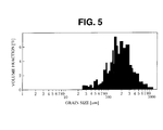
- the bonded Sm 2 Co 17 base magnet-forming ingot was measured for grain size, examining a grain size distribution. The results are plotted in the diagram of FIG. 5.
- Example 2 the bonded Sm 2 Co 17 base magnet-forming alloy was subjected to aging treatment, grinding, mixing with an epoxy resin, kneading, orientation under a magnetic field, and pressure molding. Magnetic properties of the bonded rare earth magnet were similarly measured.
- Example 2 shows the magnetic properties of the bonded Sm 2 Co 17 base magnets obtained in Example 2 and Comparative Examples 2 and 3.
- a comparison of FIGS. 3 to 5 reveals that Example 2 gives a uniform distribution centering at 50 ⁇ m whereas Comparative Example 2 gives a wide distribution with more contents of fine grains.
- the grain size of Comparative Example 3 is very large. Reflecting the grain size distribution, Example 2 exhibits superior remanence, coercivity and maximum energy product to Comparative Examples 2 and 3. Br, kG HcJ, kOe (BH)max, MGOe Example 2 7.9 13.9 14.5 Comparative Example 2 7.4 13.5 10.9 Comparative Example 3 7.5 9.8 11.1
- the bonded Sm 2 Co 17 base magnet-forming powders and the bonded Sm 2 Co 17 base magnets prepared using the same according to the invention have excellent magnetic properties.
Landscapes
- Engineering & Computer Science (AREA)
- Power Engineering (AREA)
- Chemical & Material Sciences (AREA)
- Crystallography & Structural Chemistry (AREA)
- Inorganic Chemistry (AREA)
- Hard Magnetic Materials (AREA)
- Manufacture Of Metal Powder And Suspensions Thereof (AREA)
- Manufacturing Cores, Coils, And Magnets (AREA)
- Materials Engineering (AREA)
- Mechanical Engineering (AREA)
- Metallurgy (AREA)
- Organic Chemistry (AREA)
Abstract
Description
| Average grain size, µm | Sm content, wt% | Br, kG | HcJ, kOe | (BH)max, MGOe | |
| Example 1 | 50 | 23.8 | 8.5 | 14.2 | 16.7 |
| Comparative Example 1 | 30 | 23.2 | 8.0 | 9.5 | 13.5 |
| Br, kG | HcJ, kOe | (BH)max, MGOe | |
| Example 2 | 7.9 | 13.9 | 14.5 |
| Comparative Example 2 | 7.4 | 13.5 | 10.9 |
| Comparative Example 3 | 7.5 | 9.8 | 11.1 |
Claims (6)
- A method for preparing an alloy suitable for bonded rare earth magnets, comprising the steps of:melting an alloy consisting essentially of 20 to 30% by weight of R, which is samarium or a mixture of at least two rare earth elements (which may be Y) containing at least 50% by weight of samarium, 10 to 45% by weight of iron, 1 to 10% by weight of copper, 0.5 to 5% by weight of zirconium, and the balance of cobalt,quenching the melt by a strip casting technique, to form a rare earth alloy strip containing at least 20% by volume of equiaxed crystals with a grain size of 1 to 200 µm and having a gage of 0.05 to 3 mm,heat treating the strip in a non-oxidizing atmosphere at 1000 to 1300°C for 0.5 to 20 hours,followed by aging treatment and grinding.
- A method for preparing an alloy suitable for bonded rare earth magnets, comprising the steps of:melting an alloy consisting essentially of 20 to 30% by weight of R,which is samarium or a mixture of at least two rare earth elements (which may be Y) containing at least 50% by weight of samarium, 10 to 45% by weight of iron, 1 to 10% by weight of copper, 0.5 to 5% by weight of zirconium, and the balance of cobalt,quenching the melt from a melt temperature of 1250 to 1600°C by a strip casting technique,heat treating the resulting rare earth alloy in a non-oxidizing atmosphere at 1000 to 1300°C for 0.5 to 20 hours,followed by aging treatment and grinding.
- A bonded rare earth magnet composition comprising the alloy for bonded rare earth magnets obtained by the method of claim 1 or 2 and 1 to 10% by weight of a resin.
- A bonded rare earth magnet composition comprising the alloy for bonded rare earth magnets obtained by the method of claim 2 and 1 to 10% by weight of a resin.
- A ground alloy preparation suitable for the manufacture of a bonded rare earth magnet composition, obtained or obtainable by a method according to claim 1 or claim 2.
- The use of a ground alloy preparation according to claim 5 in the manufacture of a bonded rare earth magnet composition.
Applications Claiming Priority (2)
| Application Number | Priority Date | Filing Date | Title |
|---|---|---|---|
| JP2001161165 | 2001-05-29 | ||
| JP2001161165A JP2002356717A (en) | 2001-05-29 | 2001-05-29 | Method for producing alloy for rare earth bonded magnet and rare earth bonded magnet composition |
Publications (3)
| Publication Number | Publication Date |
|---|---|
| EP1263003A2 true EP1263003A2 (en) | 2002-12-04 |
| EP1263003A3 EP1263003A3 (en) | 2003-09-24 |
| EP1263003B1 EP1263003B1 (en) | 2009-08-05 |
Family
ID=19004484
Family Applications (1)
| Application Number | Title | Priority Date | Filing Date |
|---|---|---|---|
| EP02253685A Expired - Lifetime EP1263003B1 (en) | 2001-05-29 | 2002-05-24 | Preparation of a rare earth magnet alloy powder for a bonded magnet and rare earth bonded magnet therewith |
Country Status (7)
| Country | Link |
|---|---|
| US (1) | US6793742B2 (en) |
| EP (1) | EP1263003B1 (en) |
| JP (1) | JP2002356717A (en) |
| KR (1) | KR20030006973A (en) |
| CN (1) | CN1292442C (en) |
| DE (1) | DE60233185D1 (en) |
| TW (1) | TW554353B (en) |
Families Citing this family (8)
| Publication number | Priority date | Publication date | Assignee | Title |
|---|---|---|---|---|
| JP4276541B2 (en) * | 2001-11-09 | 2009-06-10 | 株式会社三徳 | Alloy for Sm-Co magnet, method for producing the same, sintered magnet, and bonded magnet |
| JP4227326B2 (en) * | 2001-11-28 | 2009-02-18 | Dowaホールディングス株式会社 | Manufacturing method of ring-shaped thin plate made of sintered rare earth magnet alloy |
| US7648933B2 (en) | 2006-01-13 | 2010-01-19 | Dynamic Abrasives Llc | Composition comprising spinel crystals, glass, and calcium iron silicate |
| CN101477863B (en) * | 2008-01-02 | 2013-01-16 | 有研稀土新材料股份有限公司 | Samarium - cobalt magnetic powder and preparation thereof |
| JP5908836B2 (en) * | 2010-07-02 | 2016-04-26 | 株式会社三徳 | Method for producing alloy cast for rare earth sintered magnet |
| JP6076705B2 (en) * | 2012-11-20 | 2017-02-08 | 株式会社東芝 | Permanent magnet and motor and generator using the same |
| CN103194709A (en) * | 2013-04-01 | 2013-07-10 | 何迎春 | Preparation method of metallic composite material |
| JP6287167B2 (en) * | 2013-07-16 | 2018-03-07 | Tdk株式会社 | Rare earth magnets |
Family Cites Families (10)
| Publication number | Priority date | Publication date | Assignee | Title |
|---|---|---|---|---|
| JPS56102533A (en) | 1980-01-16 | 1981-08-17 | Seiko Epson Corp | Manufacture of rare earth element-cobalt permanent magnet alloy |
| JPH04146604A (en) | 1990-10-09 | 1992-05-20 | Seiko Epson Corp | Manufacturing method of rare earth bonded magnet alloy |
| JPH04152603A (en) | 1990-10-17 | 1992-05-26 | Seiko Epson Corp | Manufacturing method of rare earth bonded magnet alloy |
| JPH0757909A (en) | 1994-06-06 | 1995-03-03 | Seiko Epson Corp | Manufacturing method of cast ingot for rare earth permanent magnet |
| JP3505261B2 (en) | 1995-03-17 | 2004-03-08 | 株式会社三徳 | Sm-Co permanent magnet material, permanent magnet and method for producing the same |
| TW338167B (en) * | 1995-10-18 | 1998-08-11 | Seiko Epson Corp | Rare-earth adhesive magnet and rare-earth adhesive magnet components |
| US6001272A (en) * | 1996-03-18 | 1999-12-14 | Seiko Epson Corporation | Method for producing rare earth bond magnet, composition for rare earth bond magnet, and rare earth bond magnet |
| JP2000348918A (en) * | 1999-06-02 | 2000-12-15 | Seiko Epson Corp | Rare earth bonded magnet, composition for bonded rare earth magnet, and method for manufacturing rare earth bonded magnet |
| JP2001126906A (en) | 1999-10-28 | 2001-05-11 | Seiko Instruments Inc | Method for producing SmCo permanent magnet powder, permanent magnet powder, and bonded magnet |
| DE60140783D1 (en) * | 2000-09-08 | 2010-01-28 | Shinetsu Chemical Co | Rare earth alloy, rare earth sintered magnet and manufacturing process |
-
2001
- 2001-05-29 JP JP2001161165A patent/JP2002356717A/en active Pending
-
2002
- 2002-05-14 TW TW091110051A patent/TW554353B/en active
- 2002-05-21 US US10/151,096 patent/US6793742B2/en not_active Expired - Lifetime
- 2002-05-24 DE DE60233185T patent/DE60233185D1/en not_active Expired - Fee Related
- 2002-05-24 EP EP02253685A patent/EP1263003B1/en not_active Expired - Lifetime
- 2002-05-28 KR KR1020020029475A patent/KR20030006973A/en not_active Ceased
- 2002-05-29 CN CNB021217491A patent/CN1292442C/en not_active Expired - Fee Related
Also Published As
| Publication number | Publication date |
|---|---|
| JP2002356717A (en) | 2002-12-13 |
| TW554353B (en) | 2003-09-21 |
| US6793742B2 (en) | 2004-09-21 |
| KR20030006973A (en) | 2003-01-23 |
| DE60233185D1 (en) | 2009-09-17 |
| EP1263003B1 (en) | 2009-08-05 |
| EP1263003A3 (en) | 2003-09-24 |
| CN1292442C (en) | 2006-12-27 |
| CN1388536A (en) | 2003-01-01 |
| US20030062098A1 (en) | 2003-04-03 |
Similar Documents
| Publication | Publication Date | Title |
|---|---|---|
| US7691323B2 (en) | Rare-earth alloy, rare-earth sintered magnet, and methods of manufacturing | |
| KR0131333B1 (en) | Alloy Ingots for Permanent Magnets, Anisotropic Powders for Permanent Magnets, Manufacturing Methods and Their Permanent Magnets | |
| US5908513A (en) | Cast alloy used for production of rare earth magnet and method for producing cast alloy and magnet | |
| JP4389427B2 (en) | Sintered magnet using alloy powder for rare earth-iron-boron magnet | |
| JPH1036949A (en) | Alloy for rare earth magnet and its production | |
| EP0632471B1 (en) | Process of preparing a permanent magnet containing rare earth metal, boron and iron | |
| US5690752A (en) | Permanent magnet containing rare earth metal, boron and iron | |
| JP3505261B2 (en) | Sm-Co permanent magnet material, permanent magnet and method for producing the same | |
| US6793742B2 (en) | Preparation of bonded rare earth magnet-forming alloy and bonded rare earth magnet composition | |
| JP2001355050A (en) | RTBC rare earth magnetic powder and bonded magnet | |
| JPH05222488A (en) | Alloy ingot for permanent magnet and its manufacture | |
| JP2002175908A (en) | Permanent magnet having plural ferromagnetic phases, and its manufacturing method | |
| JP3299630B2 (en) | Manufacturing method of permanent magnet | |
| JP2002212686A (en) | Paridly cooled alloy for iron based rare earth alloy magnet and method for producing iron based rare earth alloy magnet | |
| JP4574820B2 (en) | Method for producing magnet powder for rare earth bonded magnet | |
| JP3726888B2 (en) | Rare earth alloy and manufacturing method thereof, and manufacturing method of rare earth sintered magnet | |
| JPH07109504A (en) | Production of raw powder for anisotropic bond magnet | |
| JP4457453B2 (en) | Fine crystal iron-based alloy magnet and method for producing the same | |
| JP2002083728A (en) | Method of manufacturing rare earth permanent magnet | |
| JP3548568B2 (en) | Method for producing rare earth metal-iron based permanent magnet alloy containing nitrogen atom | |
| JP3213638B2 (en) | Method for producing powder for rare earth metal-iron-boron based anisotropic permanent magnet | |
| JPH05320832A (en) | Alloy cast ingot for rare earth metal-iron permanent magnet and its production and permanent magnet | |
| JPH05320831A (en) | Alloy for permanent magnet | |
| JPH0757910A (en) | Method for producing anisotropic magnetic powder and method for producing anisotropic bonded magnet | |
| JPH0439206B2 (en) |
Legal Events
| Date | Code | Title | Description |
|---|---|---|---|
| PUAI | Public reference made under article 153(3) epc to a published international application that has entered the european phase |
Free format text: ORIGINAL CODE: 0009012 |
|
| AK | Designated contracting states |
Kind code of ref document: A2 Designated state(s): AT BE CH CY DE DK ES FI FR GB GR IE IT LI LU MC NL PT SE TR |
|
| AX | Request for extension of the european patent |
Free format text: AL;LT;LV;MK;RO;SI |
|
| PUAL | Search report despatched |
Free format text: ORIGINAL CODE: 0009013 |
|
| AK | Designated contracting states |
Kind code of ref document: A3 Designated state(s): AT BE CH CY DE DK ES FI FR GB GR IE IT LI LU MC NL PT SE TR |
|
| AX | Request for extension of the european patent |
Extension state: AL LT LV MK RO SI |
|
| 17P | Request for examination filed |
Effective date: 20031107 |
|
| AKX | Designation fees paid |
Designated state(s): DE FR GB |
|
| 17Q | First examination report despatched |
Effective date: 20051221 |
|
| GRAP | Despatch of communication of intention to grant a patent |
Free format text: ORIGINAL CODE: EPIDOSNIGR1 |
|
| GRAS | Grant fee paid |
Free format text: ORIGINAL CODE: EPIDOSNIGR3 |
|
| GRAA | (expected) grant |
Free format text: ORIGINAL CODE: 0009210 |
|
| RIN1 | Information on inventor provided before grant (corrected) |
Inventor name: MINOWA, TAKEHISA,C/O MAGNETIC MATERIALS RES. CTR. Inventor name: HASHIMOTO, TAKAHIRO,C/O MAGNETIC MATERIALS RES. CT Inventor name: SATO, KOJI,C/O MAGNETIC MATERIALS RES. CTR. Inventor name: SAKAKI, KAZUAKI,C/O MAGNETIC MATERIALS RES. CTR. |
|
| AK | Designated contracting states |
Kind code of ref document: B1 Designated state(s): DE FR GB |
|
| REG | Reference to a national code |
Ref country code: GB Ref legal event code: FG4D |
|
| REF | Corresponds to: |
Ref document number: 60233185 Country of ref document: DE Date of ref document: 20090917 Kind code of ref document: P |
|
| PLBE | No opposition filed within time limit |
Free format text: ORIGINAL CODE: 0009261 |
|
| STAA | Information on the status of an ep patent application or granted ep patent |
Free format text: STATUS: NO OPPOSITION FILED WITHIN TIME LIMIT |
|
| 26N | No opposition filed |
Effective date: 20100507 |
|
| GBPC | Gb: european patent ceased through non-payment of renewal fee |
Effective date: 20100524 |
|
| REG | Reference to a national code |
Ref country code: FR Ref legal event code: ST Effective date: 20110131 |
|
| PG25 | Lapsed in a contracting state [announced via postgrant information from national office to epo] |
Ref country code: DE Free format text: LAPSE BECAUSE OF NON-PAYMENT OF DUE FEES Effective date: 20101201 |
|
| PG25 | Lapsed in a contracting state [announced via postgrant information from national office to epo] |
Ref country code: FR Free format text: LAPSE BECAUSE OF NON-PAYMENT OF DUE FEES Effective date: 20100531 |
|
| PG25 | Lapsed in a contracting state [announced via postgrant information from national office to epo] |
Ref country code: GB Free format text: LAPSE BECAUSE OF NON-PAYMENT OF DUE FEES Effective date: 20100524 |