EP1261202A2 - Méthode et appareil pour l'enregistrement et la reproduction des informations vidéo - Google Patents
Méthode et appareil pour l'enregistrement et la reproduction des informations vidéo Download PDFInfo
- Publication number
- EP1261202A2 EP1261202A2 EP02013990A EP02013990A EP1261202A2 EP 1261202 A2 EP1261202 A2 EP 1261202A2 EP 02013990 A EP02013990 A EP 02013990A EP 02013990 A EP02013990 A EP 02013990A EP 1261202 A2 EP1261202 A2 EP 1261202A2
- Authority
- EP
- European Patent Office
- Prior art keywords
- information
- video
- aspect ratio
- pack
- control information
- Prior art date
- Legal status (The legal status is an assumption and is not a legal conclusion. Google has not performed a legal analysis and makes no representation as to the accuracy of the status listed.)
- Granted
Links
Images


Classifications
-
- G—PHYSICS
- G11—INFORMATION STORAGE
- G11B—INFORMATION STORAGE BASED ON RELATIVE MOVEMENT BETWEEN RECORD CARRIER AND TRANSDUCER
- G11B20/00—Signal processing not specific to the method of recording or reproducing; Circuits therefor
- G11B20/00086—Circuits for prevention of unauthorised reproduction or copying, e.g. piracy
- G11B20/00731—Circuits for prevention of unauthorised reproduction or copying, e.g. piracy involving a digital rights management system for enforcing a usage restriction
- G11B20/00746—Circuits for prevention of unauthorised reproduction or copying, e.g. piracy involving a digital rights management system for enforcing a usage restriction wherein the usage restriction can be expressed as a specific number
- G11B20/00753—Circuits for prevention of unauthorised reproduction or copying, e.g. piracy involving a digital rights management system for enforcing a usage restriction wherein the usage restriction can be expressed as a specific number wherein the usage restriction limits the number of copies that can be made, e.g. CGMS, SCMS, or CCI flags
- G11B20/00768—Circuits for prevention of unauthorised reproduction or copying, e.g. piracy involving a digital rights management system for enforcing a usage restriction wherein the usage restriction can be expressed as a specific number wherein the usage restriction limits the number of copies that can be made, e.g. CGMS, SCMS, or CCI flags wherein copy control information is used, e.g. for indicating whether a content may be copied freely, no more, once, or never, by setting CGMS, SCMS, or CCI flags
-
- G—PHYSICS
- G11—INFORMATION STORAGE
- G11B—INFORMATION STORAGE BASED ON RELATIVE MOVEMENT BETWEEN RECORD CARRIER AND TRANSDUCER
- G11B20/00—Signal processing not specific to the method of recording or reproducing; Circuits therefor
- G11B20/00086—Circuits for prevention of unauthorised reproduction or copying, e.g. piracy
-
- G—PHYSICS
- G11—INFORMATION STORAGE
- G11B—INFORMATION STORAGE BASED ON RELATIVE MOVEMENT BETWEEN RECORD CARRIER AND TRANSDUCER
- G11B20/00—Signal processing not specific to the method of recording or reproducing; Circuits therefor
- G11B20/10—Digital recording or reproducing
- G11B20/12—Formatting, e.g. arrangement of data block or words on the record carriers
-
- G—PHYSICS
- G11—INFORMATION STORAGE
- G11B—INFORMATION STORAGE BASED ON RELATIVE MOVEMENT BETWEEN RECORD CARRIER AND TRANSDUCER
- G11B27/00—Editing; Indexing; Addressing; Timing or synchronising; Monitoring; Measuring tape travel
- G11B27/10—Indexing; Addressing; Timing or synchronising; Measuring tape travel
- G11B27/102—Programmed access in sequence to addressed parts of tracks of operating record carriers
- G11B27/105—Programmed access in sequence to addressed parts of tracks of operating record carriers of operating discs
-
- G—PHYSICS
- G11—INFORMATION STORAGE
- G11B—INFORMATION STORAGE BASED ON RELATIVE MOVEMENT BETWEEN RECORD CARRIER AND TRANSDUCER
- G11B27/00—Editing; Indexing; Addressing; Timing or synchronising; Monitoring; Measuring tape travel
- G11B27/10—Indexing; Addressing; Timing or synchronising; Measuring tape travel
- G11B27/19—Indexing; Addressing; Timing or synchronising; Measuring tape travel by using information detectable on the record carrier
- G11B27/28—Indexing; Addressing; Timing or synchronising; Measuring tape travel by using information detectable on the record carrier by using information signals recorded by the same method as the main recording
- G11B27/30—Indexing; Addressing; Timing or synchronising; Measuring tape travel by using information detectable on the record carrier by using information signals recorded by the same method as the main recording on the same track as the main recording
- G11B27/3027—Indexing; Addressing; Timing or synchronising; Measuring tape travel by using information detectable on the record carrier by using information signals recorded by the same method as the main recording on the same track as the main recording used signal is digitally coded
-
- G—PHYSICS
- G11—INFORMATION STORAGE
- G11B—INFORMATION STORAGE BASED ON RELATIVE MOVEMENT BETWEEN RECORD CARRIER AND TRANSDUCER
- G11B27/00—Editing; Indexing; Addressing; Timing or synchronising; Monitoring; Measuring tape travel
- G11B27/10—Indexing; Addressing; Timing or synchronising; Measuring tape travel
- G11B27/19—Indexing; Addressing; Timing or synchronising; Measuring tape travel by using information detectable on the record carrier
- G11B27/28—Indexing; Addressing; Timing or synchronising; Measuring tape travel by using information detectable on the record carrier by using information signals recorded by the same method as the main recording
- G11B27/32—Indexing; Addressing; Timing or synchronising; Measuring tape travel by using information detectable on the record carrier by using information signals recorded by the same method as the main recording on separate auxiliary tracks of the same or an auxiliary record carrier
- G11B27/327—Table of contents
- G11B27/329—Table of contents on a disc [VTOC]
-
- H—ELECTRICITY
- H04—ELECTRIC COMMUNICATION TECHNIQUE
- H04N—PICTORIAL COMMUNICATION, e.g. TELEVISION
- H04N5/00—Details of television systems
- H04N5/76—Television signal recording
- H04N5/91—Television signal processing therefor
- H04N5/913—Television signal processing therefor for scrambling ; for copy protection
-
- G—PHYSICS
- G11—INFORMATION STORAGE
- G11B—INFORMATION STORAGE BASED ON RELATIVE MOVEMENT BETWEEN RECORD CARRIER AND TRANSDUCER
- G11B2220/00—Record carriers by type
- G11B2220/20—Disc-shaped record carriers
- G11B2220/21—Disc-shaped record carriers characterised in that the disc is of read-only, rewritable, or recordable type
- G11B2220/215—Recordable discs
- G11B2220/216—Rewritable discs
-
- G—PHYSICS
- G11—INFORMATION STORAGE
- G11B—INFORMATION STORAGE BASED ON RELATIVE MOVEMENT BETWEEN RECORD CARRIER AND TRANSDUCER
- G11B2220/00—Record carriers by type
- G11B2220/20—Disc-shaped record carriers
- G11B2220/25—Disc-shaped record carriers characterised in that the disc is based on a specific recording technology
- G11B2220/2537—Optical discs
- G11B2220/2562—DVDs [digital versatile discs]; Digital video discs; MMCDs; HDCDs
- G11B2220/2575—DVD-RAMs
-
- G—PHYSICS
- G11—INFORMATION STORAGE
- G11B—INFORMATION STORAGE BASED ON RELATIVE MOVEMENT BETWEEN RECORD CARRIER AND TRANSDUCER
- G11B27/00—Editing; Indexing; Addressing; Timing or synchronising; Monitoring; Measuring tape travel
- G11B27/02—Editing, e.g. varying the order of information signals recorded on, or reproduced from, record carriers
- G11B27/031—Electronic editing of digitised analogue information signals, e.g. audio or video signals
- G11B27/034—Electronic editing of digitised analogue information signals, e.g. audio or video signals on discs
-
- H—ELECTRICITY
- H04—ELECTRIC COMMUNICATION TECHNIQUE
- H04N—PICTORIAL COMMUNICATION, e.g. TELEVISION
- H04N5/00—Details of television systems
- H04N5/76—Television signal recording
- H04N5/91—Television signal processing therefor
- H04N5/913—Television signal processing therefor for scrambling ; for copy protection
- H04N2005/91307—Television signal processing therefor for scrambling ; for copy protection by adding a copy protection signal to the video signal
- H04N2005/91328—Television signal processing therefor for scrambling ; for copy protection by adding a copy protection signal to the video signal the copy protection signal being a copy management signal, e.g. a copy generation management signal [CGMS]
-
- H—ELECTRICITY
- H04—ELECTRIC COMMUNICATION TECHNIQUE
- H04N—PICTORIAL COMMUNICATION, e.g. TELEVISION
- H04N5/00—Details of television systems
- H04N5/76—Television signal recording
- H04N5/91—Television signal processing therefor
- H04N5/913—Television signal processing therefor for scrambling ; for copy protection
- H04N2005/91357—Television signal processing therefor for scrambling ; for copy protection by modifying the video signal
- H04N2005/91364—Television signal processing therefor for scrambling ; for copy protection by modifying the video signal the video signal being scrambled
Definitions
- This invention relates to an information recording/reproducing apparatus as well as to an information recording/reproducing method with a functional features of forming a video pack, forming a file to be recorded and processing control information.
- This invention may typically be applicable to a recording/reproducing apparatus such as one adapted to use a DVD (digital versatile disk), one comprising a hard disk or a built-in large capacity semiconductor memory, or one adapted to simultaneously use a hard disk and a removable DVD, or similar, storage medium.
- DVD digital versatile disk
- a recording/reproducing apparatus such as one adapted to use a DVD (digital versatile disk), one comprising a hard disk or a built-in large capacity semiconductor memory, or one adapted to simultaneously use a hard disk and a removable DVD, or similar, storage medium.
- This standard is adapted to support the MPEG 2 System for moving image compression and also the AC3 Audio Compression System and the MPEG Audio Compression System for audio compression. It is also adapted to handle sub image data obtained by run length compression of bit map data for superimposition in movies and karaoke videos. This standard also defines control data (navi-pack) for special reproduction operations, such as fast forwarding and fast rewinding in reproducing apparatuses. Furthermore, this standard is also adapted to support the standards for ISO9660 anc micro UDF.
- DVD-RAMs with a storage capacity of about 4.7 GB
- the standard for DVD-RAMs (with a storage capacity of about 4.7 GB) has been completed for the media and DVD-RAM drives have been pupularly marketed as peripheral devices of computers.
- RTR real time recording
- HDD hard disk drive
- a signal of a broadcast program (or a signal reproduced from some other recording medium) is input to a recording/reproducing apparatus, which converts the program signal into a predetermined format and stores it in a recording medium.
- Such recording operations will be carried out in preset intermittent program recording time slots.
- a number of programs will be temporarily stored in a built-in storage medium. Then, different programs will be combined and edited by cutting off parts of them.
- the relationship between the copy control information (CCI) defined in the real time recording control information (RDI) for the format of DVD-RAM and the control information defined in the video pack of a video packet is not specifically defined in apparatuses adapted to use a DVD-RAM. This means that, if copy prohibiting information is contained in the RDI pack as a navigation that is added for a unit of a video object as defined for the DVD-RAM format, there may be cases where the video pack (the information on the MPEG format) in the unit can be taken out independently to reproduce the video, thus bypassing the prohibition.
- an information recording/reproducing apparatus for recording and playback video information comprising means for forming a video pack using an input source, the video pack including a header and video data, the header including first control information for the video pack; means for forming a file to be recorded on a recording medium, the file including one or more video objects (VOB), the VOB including one or more video object units (VOBU), the VOBU including a real time data information (RDI) pack and one or more video packs, the RDI pack including second control information for the VOBU; and means for setting the same information to the contents of the first control information and the contents of the second control information.
- VOB video objects
- VOBU video object units
- RDI real time data information
- an information recording/reproducing method for recording and playback video information comprising a step of forming a video pack using an input source, the video pack including a header and video data, the video data including first control information for the video pack; a step of forming a file to be recorded on a recording medium, the file including one or more video objects (VOB), the VOB including one or more video object units (VOBU), the VOBU including a real time data information (RDI) pack and one or more video packs, the RDI pack including second control information for the VOBU; and a step of setting the same information to the contents of the first control information and the contents of the second control information.
- VOB video objects
- VOBU video object units
- RDI real time data information
- FIG. 1 is a schematic block diagram of an embodiment of the information recording/reproducing apparatus according to the invention. While this embodiment is a recording/reproducing apparatus adapted to handle both DVD-RAMs and hard disks, it may alternatively be so arranged that the embodiment handles only one of the two types of recording medium. Still alternatively, the hard disk or the DVD-RAM may be replaced by a semiconductor memory.
- the blocks of FIG. 1 may be divided into those for recording, shown on the left side, and those for reproduction, shown on the right side.
- This embodiment of an information recording/reproducing apparatus comprises a hard disk drive section 2001, a disk drive section 1002 for driving an optical disk 1001, that performs writing information to the disk 1001 which is adapted to store composed video files, and reading information from the disk 1001, and a data processor section 1003 which is adapted to supply data to be recorded to the hard disk drive section 2001 and the disk drive section 1002, and receives signals reproduced from them.
- the data processor section 1003 is designed to handle data to be recorded or reproduced on a unit by unit basis and includes a buffer circuit, a modulator/demodulator circuit and an error correction circuit.
- This embodiment of a recording/reproducing apparatus further comprises, as major components, an encoder section 50 operating for the image recording side of the apparatus, a decoder section 60 operating for the image reproducing side of the apparatus and a microcomputer block 30 for controlling the overall operation of the apparatus main body.
- the encoder section 50 has analog/digital converters for respectively digitizing input analog video signals and input analog audio signals, a video encoder and an audio encoder, as well as a sub video encoder (or sub picture encoder), a formatter for formatting the output of each of the encoders into a predetermined DVD-RAM format, and a buffer memory.
- the encoder 50 receives external analog video signals and external analog audio signals from an AV input section 41, and analog video signals and analog audio signals from a TV (television) tuner 42.
- the encoder 50 When the encoder 50 receives digital video and audio signals, it forwards them directly to the formatter. It is also adapted to supply video and audio data respectively to a video mixing section and an audio selector, which will be described hereinafter.
- the video encoder compresses each digital video signal at a variable bit rate conforming to the MPEG 2 or MPEG 1 Standard.
- the audio encoder compresses each digital audio signal at a fixed bit rate conforming to the MPEG or AC-3 Standard or converts it into a linear PCM digital audio signal.
- sub video information e.g., a signal from a DVD video player having an independent output terminal for sub video signals
- sub video signal in the DVD video signal is encoded (run length coded) by the sub video encoder to produce a bit map for the sub video signal.
- the digital video signal, the digital audio signal and the sub video data that are encoded are put into packs by the formatter to produce video packs, audio packs and sub video packs, which are then put together and formatted to conform to a DVD Recording Standard (such as DVD-RAM, DVD-R or DVD-RW).
- a DVD Recording Standard such as DVD-RAM, DVD-R or DVD-RW.
- the information (video packs, audio packs and sub video packs) encoded by the encoder section 50 and the control information prepared by the latter may be supplied to and stored in the hard disk drive 2001 by way of the data processor 1003. Additionally, the information recorded in the hard disk may be copied or transferred to the optical disk 1001 by way of the data processor 1003 and the disk drive 1002. This is because the information stored in the hard disk and the information stored in the optical disk 1001 have the same data format.
- the information encoded by the encoder 50 and the control information prepared by the latter may be directly stored in the optical disk 1001 by way of the data processor 1003 and the disk drive 1002. Furthermore, any of the files or video objects stored in the optical disk 1001 and/or the hard disk may be erased.
- the disk drive section 1002 has a rotation control system for the optical disk 1001, a laser drive system, an optical system and so on.
- the microcomputer block 30 includes an MPU (micro-processing unit) or a CPU (central processing unit), a ROM storing control programs and a RAM to be used for providing work areas necessary for executing programs.
- MPU micro-processing unit
- CPU central processing unit
- ROM read-only memory
- RAM random access memory
- the MPU of the microcomputer block 30 performs operations in accordance with the control programs stored in the ROM such as detecting defective areas and unused storage areas, selecting an area for recording video information, recording UDF and selecting an AV address, utilizing the RAM as a work area.
- the microcomputer block 30 also includes information processing sections that are required to control the overall system such as a work RAM, a directory detector, a VMG information (overall video management information) generating section, a copy-related information detector section, a copy and scrambling information processing section (RDI processing section), a packet header processing section, a sequence header processing section and an aspect ratio information processing section.
- information processing sections that are required to control the overall system such as a work RAM, a directory detector, a VMG information (overall video management information) generating section, a copy-related information detector section, a copy and scrambling information processing section (RDI processing section), a packet header processing section, a sequence header processing section and an aspect ratio information processing section.
- the microcomputer block 30 additionally includes a key input section 44 for entering operation signals to be used for operating the apparatus.
- the microcomputer block 30 operates to control the disk drive 1002, the data processor 1003, the encoder 50 and/or the decoder 60, and so on at respective timings as determined on the basis of the timing data from the STC 38. While signal recording/reproducing operations are normally conducted in synchronism with the time clock of the STC 38, other processing operations may be carried out independently from the STC 38.
- the decoder section 60 has a separator for separating and taking out each pack from a signal of a DVD format having a pack structure, a memory to be used for the operation of separating packs and other signal processing operations, a V decoder for decoding the main video data (the contents of the main video pack) separated by the separator, an SP decoder for decoding the sub picture data (the contents of the sub video pack) separated by the separator and an A decoder for decoding the audio data (the contents of the audio pack) separated by the separator. It additionally has a video processor for appropriately synthetically combining the decoded main video data and the decoded sub video data and outputting a signal for the main image superimposed with a menu, highlighted buttons and/or captions.
- the output video signal of the decoder 60 is then input to a video mixer 71, which is adapted to synthesize text data.
- the video mixer 71 is connected to a line by which signals can be directly taken in from the TV tuner 41 or the A/V input section 42.
- a frame memory 72 that is used as a buffer is connected to the video mixer 71.
- the video mixer 71 outputs a digital signal, it is output externally by way of an interface (I/F) 73.
- the video mixer 71 outputs an analog signal, it is output externally by way of a digital/analog converter 74.
- the output audio signal of the decoder section 60 is sent to a digital/analog converter 77 by way of a selector 76 and converted into an analog signal there before it is externally output.
- the selector 76 is controlled by a selection signal from the microcomputer block 30. Therefore, it is possible to directly monitor the digital signal coming from the TV tuner 41 or the A/V input section 42 through the encoder 50.
- the formatter of the encoder 50 prepares section information (e.g., information on GOP head interrupt) during a recording session and periodically transmits it to the microcomputer block 30.
- Section information may include the number of packs of the VOBU, the end address of the I picture starting from the head of the VOBU and the reproduction time of the VOBU.
- STI VOB stream information
- a single video file is stored on a recording/reproducing DVD.
- a unit of a contiguous sector is referred to as a CDA (contiguous data area), which represents a predefined data size necessary for realizing seamless reproduction of data.
- a CDA is defined on the basis of a unit of ECC (error correction code) block. Therefore, it is preferable that a CDA is made to have a size of a multiple of 16 sectors, and data are recorded by file systems on a CDA by CDA basis.
- the data processor 1003 receives data from the formatter of the encoder 50 on a VOBU by VOBU basis and feeds the disk drive 1002 with data on a CDA by CDA basis.
- the MPU of the microcomputer block 30 prepares control information necessary for reproducing recorded data and, upon recognizing a command for completing the data recording session, it transmits the control information it has prepared to the data processor 1003. As a result, the control information is stored in the disk.
- the MPU of the microcomputer block 30 receives information of the data unit (sectional information and so on) from the encoder 50. Additionally, when a recording session is started, the MPU of the microcomputer 30 recognizes the control information read out from the disk (file system) and the unused (unrecorded) areas of the disk and specifies data recording areas to be used for the recording session by way of the data processor 1003.
- VOB video object
- a VOB is referred to as VR_MOVIE.
- Video files have a hierarchical structure and a video file comprises one or more than one VOBs (video objects).
- Each VOB is formed by one or more than one VOBUs (video object units) and each VOBU is formed by a plurality of packs.
- the packs may be RDI packs of unit control information, V (video) packs, A (audio) packs and/or sub video packs (SP packs).
- An RDI pack is also referred to as a real time data information pack (RDI_PCK).
- the pack contains information indicating the time of starting the reproduction of the first field of the VOBU to which the pack belongs, information indicating the time of recording of the VOBU and information on the manufacturer (MNF 1) as well as display control information (DCI) and copy control information (CCI).
- the display control information includes aspect ratio information, subtitle mode information and film camera mode information.
- the copy control information (CCI) includes copy authorization information (0, 0) and copy prohibition information (copy non-authorization information (1, 1).
- a V pack is formed by compressing video data according to a processing method conforming to MPEG 2 and comprises a pack header, a packet header and a video data section.
- An A pack is formed by a linear PCM, MPEG or AC3 processing method and comprises a pack header, a packet header and an audio data section.
- Control information is also referred to as video manager (VMG) and the program chain (PGC) for controlling the sequence of reproduction of data is defined in it.
- a cell is defined in the program chain (PGC) and video object information (VOBI) that is information on the video object (VOB) to be reproduced is defined in the cell.
- program chain information contains specific information on the PGC.
- a time map is described in VOBI and can be used to specify the VOBUs that constitute the VOB corresponding to the VOBI.
- the link from a cell to VOBI is identified by a logical address.
- the link from TMAP information to a VOB and the VOBUs therein is realized on the basis of the stream number of the VOB, the number of VOBUs in the VOB, the entry number of each of the VOBUs and the logical address to each target VOBU.
- FIG. 3A schematically illustrates the data structure of the unit control information (e. g., navigation information or real time data information) contained in a real time data information pack (RDI_PCK), which is described above.
- real time data information includes RDI general information (RDI_GI), display control information and copy control information (DCI_CCI) and manufacturer information (MNFI).
- RDI_GI in turn includes the presentation start time (VOBU_S_PTM) of the first video field of the VOBU to which the RDI belongs and the VOBU recording time (VOBU_REC_T).
- display control information (DCI) includes aspect ratio information (of 4 bits), subtitle (caption) information (of 2 bits), reservation-related information (of 1 bit) and information on the film camera mode (of 1 bit).
- the four bits of aspect ratio information are 0000 when the video aspect ratio is 4 : 3 and 0001 when the video aspect ratio is 16 : 9. They are other than 0000 and 0001 when the source is a letter box.
- the aspect ratio of a coded video image is 4 : 3.
- the two bits of subtitle information are 01 when the subtitle is located within the displayed image and 10 when the subtitle is located outside the displayed image.
- the one bit of film camera information is 1 for a camera mode and 0 for a film mode.
- copy control information CCI includes copy generation management system (CGMS) information (of 2 bits). Copying is authorized when the two bits are 00 and prohibited (not-authorized) when they are 11.
- CGMS copy generation management system
- FIG. 4 is a schematic illustration of the information contained in the packet header of a video pack, an audio pack or a sub video pack as defined in the DVD Standard.
- a pack has a pack header.
- the pack header describes the system clock reference.
- the system clock reference is compared with the system clock in the apparatus and the obtained result is used as timing information when handling information on a pack by pack basis in the apparatus.
- a packet header is arranged behind the pack header and followed by video data, audio data or sub video data.
- a stream ID which is the identity information of packet start code, video stream, audio stream, audio stream and sub video stream is described.
- the packet header can be used to describe PES (packet elementary stream) scrambling control information (that indicates if the pack is basically scrambled or not), copyright information and information indicating if the video is original or copied. It additionally describes presentation time information (time stamp) for synchronizing the related streams (video stream, audio stream and sub video stream) that are output simultaneously.
- PES packet elementary stream
- scrambling control information that indicates if the pack is basically scrambled or not
- copyright information information indicating if the video is original or copied.
- presentation time information time stamp
- FIGS. 5A through 5D are schematic illustrations of the data structure that can be used for the copy generation management system currently in effect for broadcast signals.
- CGMS information is inserted in the 20th horizontal period in a vertical blanking period of a television signal (see FIG. 5A). It is information of 20 bits (see FIG. 5B). The first and second bits are used as word 0 and the next four bits from the third bit to the sixth bit are used as word 1 and equal to 0000, indicating that copy generation control information is found next. The bits from the seventh bit to the fourteenth bits are used as word 2 and the remaining bits from the fifteenth bit to the twentieth bit are used as CRCC, or error correction code.
- the two bits including the seventh and eighth bits represent a CGMS data, which is defined in a manner as shown in FIG. 5C.
- the two bits When the two bits are 0, 0, they signify that the video signal can be copied without restrictions.
- the two bits When the two bits are 1, 0, they signify that the video signal can be copied only once. Finally, when the two bits are 1, 1, they signify that copying the video signal is prohibited.
- the recording apparatus operates in a manner as shown in FIG. 5C when recording the video on a recording medium by referring to the CGMS information.
- the contents of the CGMS information shown in FIG. 3D are made equal to 0, 0 (copy authorizing information).
- contents of the CGMS information in the RDI shown in FIG. 3D are made equal to 1, 1 (copy prohibiting information).
- the scrambling control information of each of the packet headers in the VOBU having the RDI at the head thereof is made the same as the contents of the CGMS information in the RDI.
- This embodiment of an information recording/reproducing apparatus is characterized in that the copy control information in the unit control pack and the scrambling control information for the video signal added to all the video packs of a video object unit have an identical meaning.
- FIG. 6 is a flow chart of the processing operation of the embodiment of information recording/reproducing apparatus according to the invention for coordinating the copy control information in the RDI (see FIG. 3A) and the scrambling control information in the video packs (see FIG. 4).
- the program describing the processing procedure is set in the microcomputer block 30 shown in FIG. 1.
- the data (CGMS information) inserted into a specific horizontal period of a vertical blocking period is taken in from the externally input television signal (Step A1).
- the contents of the copy-related information as described above by referring to FIGS. 5A through 5C are determined (Step A2, A3, A4, A5).
- the copy-related information is temporarily stored. Then, it is checked if the encoding operation is progressing and an RDI pack is generated by the formatter or not (Step A6).
- Step A7 the copy control information in the RDI pack is modified to make it adapted to the contents of the temporarily stored copy-related information (Step A8).
- This modifying operation is conducted on the principle as described above by referring to FIG. 5C.
- the two bits of copy control information are made equal to 0, 0.
- the two bits are made equal to 1, 1.
- the scrambling information in the pack header of the video pack in the VOBU containing the RDI is coordinated as in the case of the RDI (Step A9). This processing operation is conducted for all the video packs in the VOBU until the next RDI pack is found for coordinating the copy-related information and the scrambling control information.
- scrambling control information of a video pack is identical to the contents of RDI in the above description, it should be noted that the scrambling control information of an audio pack and that of a sub video pack are also made to be identical with the contents of RDI in the same VOBU.
- FIG. 7 is a schematic illustration of the progress with time of a processing operation of formatting and rearranging the copy control information of a video object carried out by the formatter in the encoder 50 of FIG. 1.
- the copy-related information of the leading RDI pack of the first VOBU, or VOBU #1 is 0, 0 (authorizing any copy) and the scrambling information of the video pack (V_PCK) contained in the VOBU #1 is also made to be 0, 0.
- the CGMS information of the video signal input to the encoder 50 is changed to 1, 0 or 1, 1 in the course of the operation of processing the VOBU #1.
- the copy and scrambling information processing section of this embodiment detects the change in the CGMS information. Thereafter, the contents of the CGMS information in the RDI located at the head of the next VOB, or VOBU #2, is made to be 1, 1 (prohibiting any copy) when generating the VOBU #2.
- the scrambling control information of all the video packs coming thereafter is also made to be 1, 1. Note that, while the video pack contains only a video header and video data in FIG. 7, a video header contains a pack header and a packet header as shown in FIG. 4.
- aspect ratio information can be also controlled in a coordinated manner.
- user data including a sequence header, a GOP header, an I picture and a B picture are arranged in a predetermined order when video information is compressed.
- the sequence header describes the size and the aspect ratio of the image represented by the video signal.
- the aspect ratio information in the CGMS information inserted in a vertical blanking period of a TV signal is detected and used to describe aspect ratio information in the RDI to be recorded on the disk and in the sequence header in a coordinated manner.
- FIGS. 8A through 8C are schematic illustrations of data that can be inserted into a specific horizontal line in a vertical blanking period of a TV signal. Such data is referred to as CGMS information.
- the CGMS information is inserted typically in the twentieth horizontal period of the vertical blanking period of a TV signal (see FIG. 8A). It is information of twenty bits (see FIG. 8B). The first and second bits are used as word 0 and the next four bits from the third bit to the sixth bit are used as word 1 and equal to 0000, indicating that copy generation control information is found next. The bits from the seventh bit to the fourteenth bits are used as word 2 and the remaining bits from the fifteenth bit to the twentieth bit are used as CRCC, or error correction code.
- the two bits of the word 0 are used as aspect ratio information of the transmitted TV signal.
- FIG. 8C shows the definition of the two bits of the word 0. As shown in FIG. 8C, 0, 0 is used for a video signal with an aspect ratio of 3 : 4 or no information and 1, 0 is used for an image squeeze signal with an aspect ratio of 16 : 9, while 0, 1 is used for a letter box signal with an aspect ratio of 4 : 3 and 1, 1 is not used.
- this embodiment of a recording/reproducing apparatus adapted to process such an input television signal operates according to the definition of FIG. 8C and records the corresponding video signal on a recording medium by referring to the CGMS information. More specifically, it makes the aspect ratio information contained in the DCI in the RDI identical to the aspect ratio information contained in the CGMS information. Then, contents of the aspect ratio information in the sequence header of the compressed video signal conforming to the MPEG Standards and contained in the VOBU where the RDI is arranged at the head is made to properly correspond to the contents of the aspect ratio information in the DCI.
- FIG. 9 is a flow chart of an operation of coordinating aspect ratio information in the RDI and (see FIG. 3C) and the aspect ratio information contained in the sequence header of the compressed video signal by referring to the above described aspect ratio information in the input video signal.
- the program for this processing procedure is set in the microcomputer block 30 shown in FIG. 1.
- the data (CGMS information) inserted into a specific horizontal period of a vertical blocking period is received from the externally input television signal (Step B1).
- the contents of the aspect ratio information as described above by referring to FIGS. 8A through 8C is determined (Step B2, B3, B4, B5).
- the aspect ratio information is temporarily stored. Then, it is checked if the encoding operation is progressing and an RDI pack is generated by the formatter or not (Step B6).
- Step B7 the aspect ratio information of the DCI in the RDI pack is modified to adapt it to the contents of the temporarily-stored aspect ratio information (Step B8).
- This modifying operation is conducted on the principle as described above by referring to FIG. 8C.
- the CGMS information of the input source is determined to be 0, 0, this refers to a signal of an image with an aspect ratio of 4 : 3 and hence the aspect ratio information of the RDI is set to 0, 0, 0, 0.
- the CGMS information of the input source is determined to be 1
- this refers to a signal of an image with an aspect ratio of 16 : 9 and hence the aspect ratio information of the RDI is set to 0, 0, 0, 1.
- the CGMS information of the input source is determined to be 0, 1
- this refers to a letter box signal of an image with an aspect ratio of 4: 3 and hence the aspect ratio information of the RDI is basically set to 0, 0, 0, 0.
- Step B9 the aspect ratio information in a sequence header of the video pack in the VOBU containing the RDI is coordinated as in the case of the RDI (Step B9). This processing operation is conducted for all the video packs in the VOBU until the next RDI pack is found for coordinating the copy control information and the scrambling control information.
- FIG. 10 is a schematic illustration of the progress with time of a processing operation for formatting and rearranging video information by means of the formatter in the encoder 50 shown in FIG. 1.
- the data section of each video pack comprises a sequence header, a GOP header, a compressed I picture and a compressed B picture.
- the aspect ratio information of the leading RDI pack of the first VOBU, or VOBU #1 is 0, 0 and the aspect ratio information of the sequence header of the compressed video signal contained in the VOBU #1 is also made to be equal to 0, 0, 0, 0.
- the CGMS information of the video signal input to the encoder 50 is changed to 1, 0 or 1, 1 in the course of the operation of processing the VOBU #1.
- the copy and scrambling information processing section of this embodiment detects the change in the CGMS information. Thereafter, the contents of the CGMS information in the RDI located at the head of the next VOB, or VOBU #2, is made to be equal to 0, 0, 0, 1 (16 : 9) when generating the VOBU #2.
- the aspect ratio information of all the subsequent sequence headers is also made to be equal to 0, 0, 0, 1.
- the aspect ratio information of the RDI is basically set to 0, 0, 0, 0 when the CGMS information of the input source is determined to be 0, 0 (indicating an aspect ratio of 4: 3), whereas the aspect ratio information of the RDI is set to 0, 0, 0, 1 when the CGMS information of the input source is determined to be 1, 0 (indicating an aspect ratio of 16 : 9) in the above description, the aspect ratio information may be defined in a more detailed way by the user who is monitoring the operation. For example, values such as 1000, 0100, 1101, 0010, 1011, 0111 may be used in the case of a letter box. In this case again, the aspect ratio information of the sequence header of the video data compressed according to the MPEG Standard and the aspect ratio information of the corresponding RDI are made to be same and identical relative to each other.
- copy control information and aspect ratio information are coordinated on a video object unit basis. Therefore, in the case where the method and apparatus according to the invention are dedicated to reproduction, the data of the video object unit to which a video pack belongs may be determined to be authorizing or prohibiting copies solely depending on the video scrambling control information of the video pack (or an audio pack or a sub video pack) to simplify the information judging function of the entire apparatus. It should be appreciated that the same is true for judging aspect ratio information.
- the copy control information in the unit control information (RDI) and the scrambling control information in the packet header are coordinated in order to coordinate different pieces of copy-related information.
- the aspect ratio information in the unit control information (RDI) and the aspect ratio information in the sequence header are coordinated in order to coordinate different pieces of aspect ratio information.
- control information on a VOB unit basis (M_VOB_STI: movie video object stream information) and control information for controlling an entire video file (attribute information in the file system).
- VMGI video manager information
- the VR_MANGR. IFO is used to store navigation data for controlling program sets, programs, entry points, play lists and so on.
- VRO is a movie AV file for storing movie video objects (movie VOBs).
- VRO is a still picture AV file for storing still picture VOBs.
- VRO is a still picture annexed audio file for storing the audio streams annexed to still pictures.
- the VR_MOVIE. VRO is used to store original VOBs constituted by video parts containing arbitrarily selected sub-picture units.
- the original VOBs may include audio parts related to the video parts.
- VROS is used to store annexed audio parts, which indicate the audio streams recorded by after-recording operations.
- VRO are combined with several video parts stored in the VR_STILL.
- the VR_MANGR. BUP is a backup file of the VR_MANGR. IFO. It is prepared simultaneously with the VR_MANGR. IFO as a perfect copy of the latter but stored in a recording area different from that of the VR_MANGR. IFO.
- the disk is managed on a file unit basis and the information of each file is described in an area provided with a logical block number on the disk.
- the logical block numbers (LBN) start with a logical sector number (LSN) that refers to a physical address on the disk, for instance the 8576-th logical sector number.
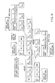
- FIG. 12 is a schematic and hierarchical illustration of the data structure of management information (to be referred to as navigation data to be used for recording/reproducing video and audio data) that is controlled in the file VR_MANGR. IFO.
- the management information includes a real time recording video manager (RTR_VMG) containing RTR video manager information (RTR_VMGI), a movie AV file information table (M_AVFIT), a still picture AV file information table (S_AVFIT), original PGC information (ORG_PGCI), a user-defined PGC information table (UD_PGCIT), a text data manager (TXTDT_MG) and a manufacturer information table (MNFIT).
- RTR_VMG real time recording video manager
- M_AVFIT movie AV file information table
- S_AVFIT still picture AV file information table
- ORG_PGCI original PGC information
- U_PGCIT user-defined PGC information table
- TXTDT_MG text data manager
- MNFIT manufacturer information table
- the RTR_VMGI describes the identifier of the manager, the start and end addresses of the manager, version information, the time zone to be used for specifying the time when the disk is used, the still time for specifying the time when a still picture is displayed at the end of a data reproducing operation, character code information to be used as text information, a resume marker to be used for indicating the interrupted position when a data reproducing operation is interrupted, information on the symbol image of the disk, information on the symbol name of the disk and so on.
- the M_AVFIT describes M_AVFIT information, the movie video object stream information of each stream (M_VOB_STI #1 through #n) and movie AV file information (M_AVFI).
- the M_AVFIT information contains the number of M_VOB_STIs.
- the M_VOB_STI contains the video attributes of the VOBs (V_ATR), the number of audio streams (AST_Ns) and so on.
- the V_ATR may include a description of aspect ratio information.
- a VOB may contain a plurality of VOBUs.
- this embodiment is provided with a means for coordinating the aspect ratio information on a VOB by VOB basis and the aspect ratio information on a VOBU by VOBU basis.
- FIG. 13 is a flow chart of the operation of another means for coordinating different pieces of aspect ratio information.
- the steps down to Step B9 are identical with the counterparts of FIG. 9.
- the data (CGMS information) inserted into a specific horizontal period of a vertical blocking period is received from the externally input television signal (Step B1). Then, the contents of the aspect ratio information as described above are determined (Step B2, B3, B4, B5). The aspect ratio information is temporarily stored. Then, it is checked if the encoding operation is progressing and an RDI pack is generated by the formatter or not (Step B6). When, an RDI pack is identified (Step B7), the aspect ratio information of the DCI in the RDI pack is modified to adapt it to the contents of the temporarily stored aspect ratio information (Step B8). This modifying operation is conducted on the principle as described above by referring to FIG. 8C.
- the CGMS information of the input source is determined to be 0, 0, this refers to a signal of an image with an aspect ratio of 4 : 3 and hence the aspect ratio information of the RDI is set to 0, 0, 0, 0.
- the CGMS information of the input source is determined to be 1
- this refers to a signal of an image with an aspect ratio of 16 : 9 and hence the aspect ratio information of the RDI is set to 0, 0, 0, 1.
- the CGMS information of the input source is determined to be 0, 1
- this refers to a letter box signal of an image with an aspect ratio of 4: 3 and hence the aspect ratio information of the RDI is basically set to 0, 0, 0, 0.
- Step B9 the aspect ratio information in the sequence header of the video pack in the VOBU containing the RDI is coordinated as in the case of the RDI (Step B9). This processing operation is conducted for all the video packs in the VOBU until the next RDI pack is found for coordinating the copy control information and the scrambling control information.
- Step B8 the contents of the RDI_CCI as determined in Step B8 are counted on a VOBU by VOBU basis and stored. More specifically, the number of VOBUs (the number of RDIs) for which the aspect ratio 4 : 3 is selected and the number of VOBUs (the number of RDIs) for which the aspect ratio of 16 : 9 is selected are respectively stored (Step B10). Thereafter, in Step B11, it is determined if the video recording operation is terminated (or the preselected automatic video recording operation is terminated) or not. If the operation is not terminated, the processing operation returns to Step A1.
- Step B11 it is determined which of the number of VOBUs for which the aspect ratio of 4 : 3 is selected and the number of VOBUs for which the aspect ratio of 16 : 9 is selected is greater.
- the number of VOBUs for which the aspect ratio of 4 : 3 is selected is greater, 00 representing the aspect ratio of 4 : 3 is described in the V_ATR. If, on the other hand, the number of VOBUs for which the aspect ratio of 16 : 9 is selected is greater, 01 representing the aspect ratio of 16 : 3 is described in the A_ATR.
- aspect ratio information can be controlled on a VOBU by VOBU basis.
- FIG. 14 is a schematic and hierarchical illustration of the information contained in the movie AV file information (M_AVFI) (to be used as management information for controlling each video object (VOB)) that is contained in the management information shown in FIG. 12.
- M_AVFI movie AV file information
- VOB video object
- the M_AVFI describes M_AVFI general information (M_AVFIGI), movie video object information search pointers (M_VOBI_SRP #1 through #n) and the pieces of movie video object information (M_VOBI #1 through #n) indicated by the respective search pointers.
- M_VOBI contains movie video object generation information (M_VOB_GI), seamless information (SMLI), audio gap information (AGAPI) and time map information (TMPI).
- M_VOB_GI in turn contains the type of the VOB, information on the time when the VOB is recorded, sub time information (the number of fields) when the VOB is recorded, the stream number of the VOB, the start time and the end time of the VOB, etc. Additionally, an area to be used for writing copy protection information is reserved in the M_VOB_GI.
- the SMLI shows the system clock reference indicating the time for handling the first pack contained in the VOB and the system clock reference indicating the time for handling the last pack contained in the VOB.
- the AGAPI describes the time for stopping the reproduction of the audio relating to the VOB (presentation time) and the audio gap length separating audio streams.
- the TMAPI describes the entry address and the entry number of the target VOBU selected out of the plurality of VOBUs contained in the VOB. In addition, the TMAPI describes the size of the VOBU.
- copy protection information can be written to the M_VOB_GI.
- copy protection information can be defined on a VOB by VOB basis. Therefore, this embodiment is provided with a means for coordinating copy-related information prepared on a VOB by VOB basis and copy-related information prepared on a VOBU by VOBU basis. This coordinating operation will be described by referring to the flow chart of FIG. 15.
- Step A9 in FIG. 15 The steps down to Step A9 in FIG. 15 are used for coordinating the contents of CGMS information prepared on a VOBU by VOBU basis as described earlier by referring to FIG. 6.
- the steps from Step A1 through Step A9 will be briefly described here.
- the data (CGMS information) inserted into a specific horizontal period of a vertical blocking period is taken in from the externally input television signal (Step A1).
- the contents of the copy-related information as described above are determined (Step A2, A3, A4, A5).
- the copy-related information is temporarily stored.
- Step A7 When an RDI pack is identified (Step A7), the copy control information in the RDI pack is modified to adapt it to the contents of the temporarily stored copy-related information (Step A8).
- This modifying operation is conducted on the principle as described above by referring to FIG. 5C.
- the two bits of copy control information are made equal to 0, 0.
- the two bits are made equal to 1, 1.
- the scrambling information in the pack header of the video pack in the VOBU containing the RDI is coordinated as in the case of the RDI (Step A9).
- Step A10 the contents of the RDI_CCI determined in Step A8 are counted on a VOBU by VOBU basis and stored. More specifically, the number of VOBUs (the number of RDIs) prohibiting any copy and the number of VOBUs (the number of RDIs) authorizing any copy are stored (Step A10). Then, in Step A11, it is determined if the video recording operation is terminated (or the preselected automatic video recording operation is terminated) or not. If the operation is not terminated, the processing operation returns to Step A1. If, on the other hand, the operation is terminated, it is determined which of the number of VOBUs prohibiting copying and the number of VOBUs authorizing copying is greater (Step A12).
- the copy protection information described in the V_ATR (FIG. 14) is added to the copy prohibiting description and the video recording operation is terminated. If, to the contrary, the number of VOBUs authorizing copying is greater than the number of VOBUs prohibiting any copy, the copy protection information described in the V_ATR (FIG. 14) is added to the copy authorizing description and the video recording operation is terminated.
- the number of VOBUs prohibiting copying and that of VOBUs authorizing copying are compared and the copy protection information is determined for each VOB on a majority basis in the above description.
- the present invention is by no means limited to such an arrangement.
- copying is prohibited unconditionally for a VOB (1) when the number of VOBUs of the VOB prohibiting any copy is equal to or greater than a predetermined value or (2) when one or more than one VOBUs of the VOB prohibit any copy.
- the above described embodiment is adapted to manage copy-related information and aspect ratio information on a VOBU by VOBU basis and also on a VOB by VOB basis.
- copy-related information is also found in management information for controlling an entire video file (attribute information in a file system).
- FIG. 16 is a schematic illustration of information on the file configuration of a DVD file systems.
- a file entry to be used for entering a DVD-RTAV file is described in the logical block number (LBN) 145.
- LBN logical block number
- the number of the logical block where the main body (data) of the file is described is shown in the file entry. Therefore, the DVD-RTAV file can be accessed as the reproduction system refers to the logical block number.
- file identifier descriptors are described in the information on the file configuration of FIG. 16.
- the file identifier descriptors indicate file names.
- Information for entering the above described files of VR_MANGR. IFO, VR_MOVIE. VRO, VR_STILL. VRO, VR_AUDIO. VRO and VR_MAN GR. BUP is also described there.
- the pieces of file entry information for entering these files are described respectively in the logical blocks with numbers 147, 148, 149, 150 and 151.
- FIG. 17 is a schematic illustration of the configuration of the file entry information in FIG. 16.
- the extent attribute is described at byte position 176.
- the extent attribute describes the header check SAM, CGMS information, the data configuration type and protection system information.
- CGMS information shows the contents of the CGMS.
- the CGMS information is 0, it signifies that copying is authorized.
- it is 2, it signifies that copying is authorized only once.
- it is 3, it signifies that copying is prohibited.
- authorization and prohibition of copying can be controlled on a file by file basis by controlling the operation of rewriting the contents of the CGMS in the above extent attribute.
- FIG. 18 is a flow chart of the operation of identifying the contents of the CGMS in the file system on a file by file basis.
- Step C1 it is determined if there are a plurality of recorded VOBs or not (Step C1). If only a single VOB is recorded, copy prohibition information or copy authorization information corresponding to the copy protection information of the VOB is directly written into the CGMS of the file system (Step C4). If there is more than one recorded VOB, the contents of the copy protection information of V_ATR of each of the VOBs are temporarily stored in the storage section (Step C2). Then, it is determined if both prohibition of copying and authorization of copying exist or not (Step C3). If it is determined that they coexist, authorization of copying is selected for the CGMS of the file system (Step C5).
- Step C3 the operation proceeds to Step C4, where the copy protection information of V_ATR of one of the VOBs is directly described into the CGMS of the file system. Then, as a result, copy-related information is controlled on a file by file basis.
- the copy control information of a predetermined area (RDI) specified by the format of the DVD and the scrambling control information described in a predetermined area (pack header) specified by the MPEG_PS format are coordinated to effectively prevent unauthorized copying and reproduction. It is also possible to control copy prohibition and copy authorization information on a file by VOB or file basis.
- CCI copy control information
- the video decoder generates video packs out of an input source.
- the audio decoder generates audio packs out of the input source.
- the formatter generates video object units.
- the control section detects the copy-related information contained in said input source and rearranges the copy control information in each unit control pack so as to make it correspond to the detected copy-related information.
- the control section also rearranges the contents of the scrambling control information annexed to all the video packs in each video object unit having the rearranged copy control information at the head so as to make it correspond to the detected copy-related information.
- It may alternatively be so arranged as to determine if the data of a video object unit containing video packs are authorized to be copied or not depending on the contents of the video scrambling control information only for the video packs.
- a video object management section is provided to manage video objects, each of which is formed by assembling a plurality of video object units.
- the video object management means prepares video object management information, it detects the copy control information in each unit control pack and rearranges the copy-related information in the object management information to make it correspond to the detected copy control information.
- the video object management section manages video objects, each of which is formed by assembling a plurality of video object units.
- the control section detects the copy-related information contained in the input source and rearranges the copy control information in the unit control pack so as to make it correspond to the contents of the detected copy-related information.
- the video object management section rearranges the contents of the scrambling control information annexed to all the video packs in each video object unit having the rearranged copy control information at the head so as to make it correspond to the detected copy-related information.
- the video object management section determines if the number of pieces of copy prohibition information is greater than the number of pieces of copy authorization information or not in each piece of copy-related information of a plurality of unit control packs for the purpose of preparing object management information. Subsequently, it rearranges the copy-related information in the object management information so as to make it correspond to the contents of the copy-related information selected on a majority basis.
- a file management section is provided to manage a plurality of video objects.
- the file management means can enter the copy-related information prohibiting copying in the file management information.
- the file management means also makes a judgment on a plurality of pieces of video object management information and, when it is determined that copy-related information prohibiting copying and copy-related information authorizing copying coexist, it may rearrange the copy-related information so as to make it authorize copying.
Landscapes
- Engineering & Computer Science (AREA)
- Signal Processing (AREA)
- Computer Security & Cryptography (AREA)
- Multimedia (AREA)
- Signal Processing For Digital Recording And Reproducing (AREA)
- Television Signal Processing For Recording (AREA)
- Storage Device Security (AREA)
- Television Systems (AREA)
- Management Or Editing Of Information On Record Carriers (AREA)
Applications Claiming Priority (3)
| Application Number | Priority Date | Filing Date | Title |
|---|---|---|---|
| JP2001050455A JP3519691B2 (ja) | 2001-02-26 | 2001-02-26 | 制限情報の整合処理機能付き情報録再装置および方法 |
| JP2001050455 | 2001-02-26 | ||
| EP02004234A EP1235220B1 (fr) | 2001-02-26 | 2002-02-26 | Méthode coordonnée pour traiter des sections d'information de copie CCI et de brouillage PES et appareil d'enregistrement/reproduction video |
Related Parent Applications (1)
| Application Number | Title | Priority Date | Filing Date |
|---|---|---|---|
| EP02004234A Division EP1235220B1 (fr) | 2001-02-26 | 2002-02-26 | Méthode coordonnée pour traiter des sections d'information de copie CCI et de brouillage PES et appareil d'enregistrement/reproduction video |
Publications (3)
| Publication Number | Publication Date |
|---|---|
| EP1261202A2 true EP1261202A2 (fr) | 2002-11-27 |
| EP1261202A3 EP1261202A3 (fr) | 2006-09-27 |
| EP1261202B1 EP1261202B1 (fr) | 2008-06-11 |
Family
ID=18911406
Family Applications (2)
| Application Number | Title | Priority Date | Filing Date |
|---|---|---|---|
| EP02013990A Expired - Lifetime EP1261202B1 (fr) | 2001-02-26 | 2002-02-26 | Méthode et appareil pour l'enregistrement et la reproduction des informations vidéo |
| EP02004234A Expired - Lifetime EP1235220B1 (fr) | 2001-02-26 | 2002-02-26 | Méthode coordonnée pour traiter des sections d'information de copie CCI et de brouillage PES et appareil d'enregistrement/reproduction video |
Family Applications After (1)
| Application Number | Title | Priority Date | Filing Date |
|---|---|---|---|
| EP02004234A Expired - Lifetime EP1235220B1 (fr) | 2001-02-26 | 2002-02-26 | Méthode coordonnée pour traiter des sections d'information de copie CCI et de brouillage PES et appareil d'enregistrement/reproduction video |
Country Status (4)
| Country | Link |
|---|---|
| US (1) | US7302161B2 (fr) |
| EP (2) | EP1261202B1 (fr) |
| JP (1) | JP3519691B2 (fr) |
| DE (2) | DE60225743T2 (fr) |
Cited By (2)
| Publication number | Priority date | Publication date | Assignee | Title |
|---|---|---|---|---|
| EP1341378A2 (fr) * | 2001-02-26 | 2003-09-03 | Kabushiki Kaisha Toshiba | Appareil d'enregistrement/reproduction d'information et méthode coordonnée pour traiter de pièces d'information de forme élevée |
| EP1424854A1 (fr) * | 2002-11-29 | 2004-06-02 | Kabushiki Kaisha Toshiba | Dispositif et procédé de conversion de données vidéo |
Families Citing this family (18)
| Publication number | Priority date | Publication date | Assignee | Title |
|---|---|---|---|---|
| JP4314745B2 (ja) * | 1999-04-16 | 2009-08-19 | ソニー株式会社 | データ処理システム、データ処理方法及びデータ処理装置 |
| US7975021B2 (en) | 2000-10-23 | 2011-07-05 | Clearplay, Inc. | Method and user interface for downloading audio and video content filters to a media player |
| US6889383B1 (en) | 2000-10-23 | 2005-05-03 | Clearplay, Inc. | Delivery of navigation data for playback of audio and video content |
| JP3833951B2 (ja) * | 2002-02-28 | 2006-10-18 | 株式会社東芝 | 情報記録再生装置 |
| JP4117608B2 (ja) | 2002-12-03 | 2008-07-16 | ソニー株式会社 | 記録制御装置および記録制御方法、並びにプログラム |
| EP1613068A4 (fr) * | 2003-04-09 | 2008-04-09 | Matsushita Electric Ind Co Ltd | Procede, dispositif et logiciel de decodage d'image en synthese d'affichage d'ecran, et support d'enregistrement |
| JP4370800B2 (ja) * | 2003-04-21 | 2009-11-25 | ヤマハ株式会社 | 音楽コンテンツ利用装置及びプログラム |
| JP3908691B2 (ja) * | 2003-04-28 | 2007-04-25 | 株式会社東芝 | 情報記録媒体、録画前処理方法、情報記録方法、情報再生方法、情報記録装置および情報再生装置 |
| KR101058002B1 (ko) | 2004-02-02 | 2011-08-19 | 삼성전자주식회사 | 도메인 관리 시스템하에서의 데이터 기록 및 재생 방법 |
| ATE488006T1 (de) * | 2004-09-22 | 2010-11-15 | Koninkl Philips Electronics Nv | Verfahren zur generierung von prüfdaten |
| US7680397B2 (en) * | 2004-09-27 | 2010-03-16 | Victor Company Of Japan, Ltd. | Method and apparatus for recording data on a recording disc, and method and apparatus for restoring data recorded on a recording disc |
| JP4503419B2 (ja) * | 2004-11-11 | 2010-07-14 | パナソニック株式会社 | デジタルビデオレコーディング装置 |
| KR100671550B1 (ko) * | 2005-01-20 | 2007-01-19 | 삼성전자주식회사 | 디브이디 및 그의 복사 방법 |
| JP2006302346A (ja) * | 2005-04-15 | 2006-11-02 | Toshiba Corp | 情報記録媒体、情報記録方法、情報再生方法、情報記録装置、情報再生装置 |
| BRPI0612974A2 (pt) * | 2005-04-18 | 2010-12-14 | Clearplay Inc | produto de programa de computador, sinal de dados de computador incorporado em uma mÍdia de transmissço, mÉtodo para associar uma apresentaÇço de multimÍdia com informaÇÕes de filtro de conteédo e reprodutor de multimÍdia |
| JP2007074549A (ja) * | 2005-09-08 | 2007-03-22 | Toshiba Corp | 情報記録媒体、情報記録方法、情報再生方法、情報記録装置、情報再生装置 |
| JP2007110223A (ja) * | 2005-10-11 | 2007-04-26 | Sony Corp | 画像処理装置、撮像装置、および画像処理方法、並びにコンピュータ・プログラム |
| US20110103769A1 (en) * | 2009-10-30 | 2011-05-05 | Hank Risan | Secure time and space shifted audiovisual work |
Citations (5)
| Publication number | Priority date | Publication date | Assignee | Title |
|---|---|---|---|---|
| JPH1186437A (ja) * | 1997-09-09 | 1999-03-30 | Toshiba Corp | コピープロテクト方法及び記録再生装置 |
| EP0969462A1 (fr) * | 1998-07-03 | 2000-01-05 | Pioneer Electronic Corporation | Système d'enregistrement et de reproduction, appareil d'enregistrement et de reproduction avec fonction de protection contre la copie |
| EP1001624A2 (fr) * | 1998-11-11 | 2000-05-17 | Sony Corporation | Gestion de génération de copie |
| DE19906432C1 (de) * | 1999-02-16 | 2000-06-21 | Fraunhofer Ges Forschung | Verfahren und Vorrichtung zum Erzeugen eines Datenstroms und Verfahren und Vorrichtung zum Abspielen eines Datenstroms |
| EP1067789A1 (fr) * | 1999-07-09 | 2001-01-10 | Matsushita Electric Industrial Co., Ltd. | Un disque optique, un enregistreur, un lecteur, un procédé d'enregistrement, et un procédé de reproduction, tous utilisés pour le disque optique |
Family Cites Families (2)
| Publication number | Priority date | Publication date | Assignee | Title |
|---|---|---|---|---|
| JPH09162859A (ja) * | 1995-12-07 | 1997-06-20 | Fujitsu Ltd | スクランブル方法及び装置、デスクランブル方法及び装置、並びに、データ伝達方法及びシステム |
| JP3162049B2 (ja) | 1999-07-09 | 2001-04-25 | 松下電器産業株式会社 | 光ディスク、その記録装置、再生装置、記録方法および再生方法 |
-
2001
- 2001-02-26 JP JP2001050455A patent/JP3519691B2/ja not_active Expired - Fee Related
-
2002
- 2002-02-26 US US10/082,356 patent/US7302161B2/en not_active Expired - Fee Related
- 2002-02-26 DE DE60225743T patent/DE60225743T2/de not_active Expired - Lifetime
- 2002-02-26 EP EP02013990A patent/EP1261202B1/fr not_active Expired - Lifetime
- 2002-02-26 EP EP02004234A patent/EP1235220B1/fr not_active Expired - Lifetime
- 2002-02-26 DE DE60227025T patent/DE60227025D1/de not_active Expired - Lifetime
Patent Citations (5)
| Publication number | Priority date | Publication date | Assignee | Title |
|---|---|---|---|---|
| JPH1186437A (ja) * | 1997-09-09 | 1999-03-30 | Toshiba Corp | コピープロテクト方法及び記録再生装置 |
| EP0969462A1 (fr) * | 1998-07-03 | 2000-01-05 | Pioneer Electronic Corporation | Système d'enregistrement et de reproduction, appareil d'enregistrement et de reproduction avec fonction de protection contre la copie |
| EP1001624A2 (fr) * | 1998-11-11 | 2000-05-17 | Sony Corporation | Gestion de génération de copie |
| DE19906432C1 (de) * | 1999-02-16 | 2000-06-21 | Fraunhofer Ges Forschung | Verfahren und Vorrichtung zum Erzeugen eines Datenstroms und Verfahren und Vorrichtung zum Abspielen eines Datenstroms |
| EP1067789A1 (fr) * | 1999-07-09 | 2001-01-10 | Matsushita Electric Industrial Co., Ltd. | Un disque optique, un enregistreur, un lecteur, un procédé d'enregistrement, et un procédé de reproduction, tous utilisés pour le disque optique |
Non-Patent Citations (2)
| Title |
|---|
| PATENT ABSTRACTS OF JAPAN vol. 1999, no. 08, 30 June 1999 (1999-06-30) & JP 11 086437 A (TOSHIBA CORP), 30 March 1999 (1999-03-30) & JP 11 086437 A (TOSHIBA CORP) 30 March 1999 (1999-03-30) * |
| PIVA A ET AL: "A DWT-based object watermarking system for MPEG-4 video streams" IMAGE PROCESSING, 2000. PROCEEDINGS. 2000 INTERNATIONAL CONFERENCE ON SEPTEMBER 10-13, 2000, PISCATAWAY, NJ, USA,IEEE, vol. 3, 10 September 2000 (2000-09-10), pages 5-8, XP010529389 ISBN: 0-7803-6297-7 * |
Cited By (3)
| Publication number | Priority date | Publication date | Assignee | Title |
|---|---|---|---|---|
| EP1341378A2 (fr) * | 2001-02-26 | 2003-09-03 | Kabushiki Kaisha Toshiba | Appareil d'enregistrement/reproduction d'information et méthode coordonnée pour traiter de pièces d'information de forme élevée |
| EP1341378A3 (fr) * | 2001-02-26 | 2007-01-10 | Kabushiki Kaisha Toshiba | Appareil d'enregistrement/reproduction d'information et méthode coordonnée pour traiter de pièces d'information de forme élevée |
| EP1424854A1 (fr) * | 2002-11-29 | 2004-06-02 | Kabushiki Kaisha Toshiba | Dispositif et procédé de conversion de données vidéo |
Also Published As
| Publication number | Publication date |
|---|---|
| EP1235220A3 (fr) | 2006-09-13 |
| JP3519691B2 (ja) | 2004-04-19 |
| EP1261202A3 (fr) | 2006-09-27 |
| DE60225743T2 (de) | 2009-04-09 |
| US7302161B2 (en) | 2007-11-27 |
| DE60225743D1 (de) | 2008-05-08 |
| US20020126984A1 (en) | 2002-09-12 |
| EP1261202B1 (fr) | 2008-06-11 |
| JP2002252828A (ja) | 2002-09-06 |
| EP1235220A2 (fr) | 2002-08-28 |
| DE60227025D1 (de) | 2008-07-24 |
| EP1235220B1 (fr) | 2008-03-26 |
Similar Documents
| Publication | Publication Date | Title |
|---|---|---|
| EP1235220B1 (fr) | Méthode coordonnée pour traiter des sections d'information de copie CCI et de brouillage PES et appareil d'enregistrement/reproduction video | |
| US6603920B2 (en) | Optical disc for storing moving pictures with text information and apparatus using the disc | |
| US6259858B1 (en) | Optical disc for storing moving pictures with text information and apparatus using the disc | |
| JPWO2002028100A1 (ja) | 記録再生装置およびこの記録再生装置の録画予約方法 | |
| US7257318B2 (en) | Information recording/reproducing apparatus and method of coordinately processing pieces of aspect ratio information | |
| US7233735B2 (en) | Digital recording/reproducing apparatus with built-in storage medium | |
| US7860374B2 (en) | Information recording method, format changing method, and information reproduction method | |
| JP3764417B2 (ja) | データ再生装置及びデータ再生方法 | |
| US8059938B2 (en) | Picture recording apparatus | |
| JP2005018910A (ja) | コンテンツ記録装置、コンテンツ記録再生装置、コンテンツ記録再生システム及びコンテンツ記録再生方法 | |
| JP2004357127A (ja) | 映像記録装置及び映像記録方法 |
Legal Events
| Date | Code | Title | Description |
|---|---|---|---|
| PUAI | Public reference made under article 153(3) epc to a published international application that has entered the european phase |
Free format text: ORIGINAL CODE: 0009012 |
|
| 17P | Request for examination filed |
Effective date: 20020626 |
|
| AC | Divisional application: reference to earlier application |
Ref document number: 1235220 Country of ref document: EP |
|
| AK | Designated contracting states |
Kind code of ref document: A2 Designated state(s): AT BE CH CY DE DK ES FI FR GB GR IE IT LI LU MC NL PT SE TR |
|
| AX | Request for extension of the european patent |
Free format text: AL;LT;LV;MK;RO;SI |
|
| PUAL | Search report despatched |
Free format text: ORIGINAL CODE: 0009013 |
|
| AK | Designated contracting states |
Kind code of ref document: A3 Designated state(s): AT BE CH CY DE DK ES FI FR GB GR IE IT LI LU MC NL PT SE TR |
|
| AX | Request for extension of the european patent |
Extension state: AL LT LV MK RO SI |
|
| RIC1 | Information provided on ipc code assigned before grant |
Ipc: G11B 20/10 20060101ALI20060824BHEP Ipc: G11B 20/00 20060101AFI20060824BHEP Ipc: G11B 20/12 20060101ALI20060824BHEP Ipc: G11B 27/10 20060101ALI20060824BHEP Ipc: G11B 27/32 20060101ALI20060824BHEP Ipc: H04N 5/913 20060101ALI20060824BHEP |
|
| 17Q | First examination report despatched |
Effective date: 20061221 |
|
| AKX | Designation fees paid |
Designated state(s): DE FR GB |
|
| GRAP | Despatch of communication of intention to grant a patent |
Free format text: ORIGINAL CODE: EPIDOSNIGR1 |
|
| GRAS | Grant fee paid |
Free format text: ORIGINAL CODE: EPIDOSNIGR3 |
|
| GRAA | (expected) grant |
Free format text: ORIGINAL CODE: 0009210 |
|
| AC | Divisional application: reference to earlier application |
Ref document number: 1235220 Country of ref document: EP Kind code of ref document: P |
|
| AK | Designated contracting states |
Kind code of ref document: B1 Designated state(s): DE FR GB |
|
| REG | Reference to a national code |
Ref country code: GB Ref legal event code: FG4D |
|
| REF | Corresponds to: |
Ref document number: 60227025 Country of ref document: DE Date of ref document: 20080724 Kind code of ref document: P |
|
| PLBE | No opposition filed within time limit |
Free format text: ORIGINAL CODE: 0009261 |
|
| STAA | Information on the status of an ep patent application or granted ep patent |
Free format text: STATUS: NO OPPOSITION FILED WITHIN TIME LIMIT |
|
| 26N | No opposition filed |
Effective date: 20090312 |
|
| REG | Reference to a national code |
Ref country code: GB Ref legal event code: 732E Free format text: REGISTERED BETWEEN 20141009 AND 20141015 |
|
| REG | Reference to a national code |
Ref country code: DE Ref legal event code: R082 Ref document number: 60227025 Country of ref document: DE Representative=s name: HOFFMANN - EITLE PATENT- UND RECHTSANWAELTE PA, DE |
|
| REG | Reference to a national code |
Ref country code: DE Ref legal event code: R082 Ref document number: 60227025 Country of ref document: DE Representative=s name: HOFFMANN - EITLE PATENT- UND RECHTSANWAELTE PA, DE Effective date: 20141209 Ref country code: DE Ref legal event code: R081 Ref document number: 60227025 Country of ref document: DE Owner name: TOSHIBA SAMSUNG STORAGE TECHNOLOGY KOREA CORP., KR Free format text: FORMER OWNER: KABUSHIKI KAISHA TOSHIBA, TOKIO/TOKYO, JP Effective date: 20141209 |
|
| REG | Reference to a national code |
Ref country code: FR Ref legal event code: PLFP Year of fee payment: 14 |
|
| REG | Reference to a national code |
Ref country code: FR Ref legal event code: TP Owner name: KABUSHIKI KAISHA TOSHIBA, JP Effective date: 20151116 |
|
| REG | Reference to a national code |
Ref country code: FR Ref legal event code: PLFP Year of fee payment: 15 |
|
| PGFP | Annual fee paid to national office [announced via postgrant information from national office to epo] |
Ref country code: DE Payment date: 20160120 Year of fee payment: 15 |
|
| PGFP | Annual fee paid to national office [announced via postgrant information from national office to epo] |
Ref country code: GB Payment date: 20160121 Year of fee payment: 15 Ref country code: FR Payment date: 20160126 Year of fee payment: 15 |
|
| REG | Reference to a national code |
Ref country code: DE Ref legal event code: R119 Ref document number: 60227025 Country of ref document: DE |
|
| GBPC | Gb: european patent ceased through non-payment of renewal fee |
Effective date: 20170226 |
|
| REG | Reference to a national code |
Ref country code: FR Ref legal event code: ST Effective date: 20171031 |
|
| PG25 | Lapsed in a contracting state [announced via postgrant information from national office to epo] |
Ref country code: DE Free format text: LAPSE BECAUSE OF NON-PAYMENT OF DUE FEES Effective date: 20170901 Ref country code: FR Free format text: LAPSE BECAUSE OF NON-PAYMENT OF DUE FEES Effective date: 20170228 |
|
| PG25 | Lapsed in a contracting state [announced via postgrant information from national office to epo] |
Ref country code: GB Free format text: LAPSE BECAUSE OF NON-PAYMENT OF DUE FEES Effective date: 20170226 |