EP1261061A2 - Packing apparatus for an automated manufacturing system for a lithium secondary battery - Google Patents
Packing apparatus for an automated manufacturing system for a lithium secondary battery Download PDFInfo
- Publication number
- EP1261061A2 EP1261061A2 EP02253591A EP02253591A EP1261061A2 EP 1261061 A2 EP1261061 A2 EP 1261061A2 EP 02253591 A EP02253591 A EP 02253591A EP 02253591 A EP02253591 A EP 02253591A EP 1261061 A2 EP1261061 A2 EP 1261061A2
- Authority
- EP
- European Patent Office
- Prior art keywords
- separator
- tape
- cutting
- packing apparatus
- piece
- Prior art date
- Legal status (The legal status is an assumption and is not a legal conclusion. Google has not performed a legal analysis and makes no representation as to the accuracy of the status listed.)
- Granted
Links
Images


Classifications
-
- H—ELECTRICITY
- H01—ELECTRIC ELEMENTS
- H01M—PROCESSES OR MEANS, e.g. BATTERIES, FOR THE DIRECT CONVERSION OF CHEMICAL ENERGY INTO ELECTRICAL ENERGY
- H01M10/00—Secondary cells; Manufacture thereof
- H01M10/05—Accumulators with non-aqueous electrolyte
- H01M10/052—Li-accumulators
-
- H—ELECTRICITY
- H01—ELECTRIC ELEMENTS
- H01M—PROCESSES OR MEANS, e.g. BATTERIES, FOR THE DIRECT CONVERSION OF CHEMICAL ENERGY INTO ELECTRICAL ENERGY
- H01M10/00—Secondary cells; Manufacture thereof
- H01M10/04—Construction or manufacture in general
- H01M10/0404—Machines for assembling batteries
-
- H—ELECTRICITY
- H01—ELECTRIC ELEMENTS
- H01M—PROCESSES OR MEANS, e.g. BATTERIES, FOR THE DIRECT CONVERSION OF CHEMICAL ENERGY INTO ELECTRICAL ENERGY
- H01M10/00—Secondary cells; Manufacture thereof
- H01M10/04—Construction or manufacture in general
- H01M10/0413—Large-sized flat cells or batteries for motive or stationary systems with plate-like electrodes
-
- H—ELECTRICITY
- H01—ELECTRIC ELEMENTS
- H01M—PROCESSES OR MEANS, e.g. BATTERIES, FOR THE DIRECT CONVERSION OF CHEMICAL ENERGY INTO ELECTRICAL ENERGY
- H01M10/00—Secondary cells; Manufacture thereof
- H01M10/04—Construction or manufacture in general
- H01M10/0459—Cells or batteries with folded separator between plate-like electrodes
-
- H—ELECTRICITY
- H01—ELECTRIC ELEMENTS
- H01M—PROCESSES OR MEANS, e.g. BATTERIES, FOR THE DIRECT CONVERSION OF CHEMICAL ENERGY INTO ELECTRICAL ENERGY
- H01M10/00—Secondary cells; Manufacture thereof
- H01M10/05—Accumulators with non-aqueous electrolyte
- H01M10/058—Construction or manufacture
- H01M10/0583—Construction or manufacture of accumulators with folded construction elements except wound ones, i.e. folded positive or negative electrodes or separators, e.g. with "Z"-shaped electrodes or separators
-
- Y—GENERAL TAGGING OF NEW TECHNOLOGICAL DEVELOPMENTS; GENERAL TAGGING OF CROSS-SECTIONAL TECHNOLOGIES SPANNING OVER SEVERAL SECTIONS OF THE IPC; TECHNICAL SUBJECTS COVERED BY FORMER USPC CROSS-REFERENCE ART COLLECTIONS [XRACs] AND DIGESTS
- Y02—TECHNOLOGIES OR APPLICATIONS FOR MITIGATION OR ADAPTATION AGAINST CLIMATE CHANGE
- Y02E—REDUCTION OF GREENHOUSE GAS [GHG] EMISSIONS, RELATED TO ENERGY GENERATION, TRANSMISSION OR DISTRIBUTION
- Y02E60/00—Enabling technologies; Technologies with a potential or indirect contribution to GHG emissions mitigation
- Y02E60/10—Energy storage using batteries
-
- Y—GENERAL TAGGING OF NEW TECHNOLOGICAL DEVELOPMENTS; GENERAL TAGGING OF CROSS-SECTIONAL TECHNOLOGIES SPANNING OVER SEVERAL SECTIONS OF THE IPC; TECHNICAL SUBJECTS COVERED BY FORMER USPC CROSS-REFERENCE ART COLLECTIONS [XRACs] AND DIGESTS
- Y02—TECHNOLOGIES OR APPLICATIONS FOR MITIGATION OR ADAPTATION AGAINST CLIMATE CHANGE
- Y02P—CLIMATE CHANGE MITIGATION TECHNOLOGIES IN THE PRODUCTION OR PROCESSING OF GOODS
- Y02P70/00—Climate change mitigation technologies in the production process for final industrial or consumer products
- Y02P70/50—Manufacturing or production processes characterised by the final manufactured product
-
- Y—GENERAL TAGGING OF NEW TECHNOLOGICAL DEVELOPMENTS; GENERAL TAGGING OF CROSS-SECTIONAL TECHNOLOGIES SPANNING OVER SEVERAL SECTIONS OF THE IPC; TECHNICAL SUBJECTS COVERED BY FORMER USPC CROSS-REFERENCE ART COLLECTIONS [XRACs] AND DIGESTS
- Y10—TECHNICAL SUBJECTS COVERED BY FORMER USPC
- Y10T—TECHNICAL SUBJECTS COVERED BY FORMER US CLASSIFICATION
- Y10T156/00—Adhesive bonding and miscellaneous chemical manufacture
- Y10T156/17—Surface bonding means and/or assemblymeans with work feeding or handling means
- Y10T156/1702—For plural parts or plural areas of single part
- Y10T156/1712—Indefinite or running length work
- Y10T156/1734—Means bringing articles into association with web
-
- Y—GENERAL TAGGING OF NEW TECHNOLOGICAL DEVELOPMENTS; GENERAL TAGGING OF CROSS-SECTIONAL TECHNOLOGIES SPANNING OVER SEVERAL SECTIONS OF THE IPC; TECHNICAL SUBJECTS COVERED BY FORMER USPC CROSS-REFERENCE ART COLLECTIONS [XRACs] AND DIGESTS
- Y10—TECHNICAL SUBJECTS COVERED BY FORMER USPC
- Y10T—TECHNICAL SUBJECTS COVERED BY FORMER US CLASSIFICATION
- Y10T156/00—Adhesive bonding and miscellaneous chemical manufacture
- Y10T156/17—Surface bonding means and/or assemblymeans with work feeding or handling means
- Y10T156/1702—For plural parts or plural areas of single part
- Y10T156/1744—Means bringing discrete articles into assembled relationship
- Y10T156/1763—Magazine stack directly contacting separate work
- Y10T156/1766—Magazine movable to work
-
- Y—GENERAL TAGGING OF NEW TECHNOLOGICAL DEVELOPMENTS; GENERAL TAGGING OF CROSS-SECTIONAL TECHNOLOGIES SPANNING OVER SEVERAL SECTIONS OF THE IPC; TECHNICAL SUBJECTS COVERED BY FORMER USPC CROSS-REFERENCE ART COLLECTIONS [XRACs] AND DIGESTS
- Y10—TECHNICAL SUBJECTS COVERED BY FORMER USPC
- Y10T—TECHNICAL SUBJECTS COVERED BY FORMER US CLASSIFICATION
- Y10T29/00—Metal working
- Y10T29/53—Means to assemble or disassemble
- Y10T29/5313—Means to assemble electrical device
- Y10T29/53135—Storage cell or battery
Definitions
- the present invention relates to a packing apparatus for an automated manufacturing system of a lithium secondary battery.
- the present invention relates to a packing apparatus for use with an automated manufacturing system such as that described in the applicant's co-pending European patent application which claims priority from Korean patent application No. 2001-028493.
- lithium secondary batteries are used as power sources of electronic products, and, in particular, lithium secondary batteries are generally used taking into consideration the use life and capacity thereof.
- the lithium secondary batteries are classified into lithium metal batteries and lithium ion batteries which employ liquid electrolyte, and lithium polymer batteries which employ solid polymer electrolyte.
- the lithium polymer batteries are classified into full-solid type lithium polymer batteries in which organic electrolytic liquid is not included at all, and lithium ion polymer batteries employing gel type polymer electrolyte containing organic electrolytic liquid.
- the lithium secondary battery is manufactured by stacking a plurality of unit cells having a separator-electrode structure so as to meet a required capacity, connecting the unit cells to each other in parallel, and packing the unit cells into a cylindrical or polyhedral can.
- a packing apparatus for an automated manufacturing system of a secondary lithium battery comprising: a frame; abase member which is installed at the frame, and is provided with a receiving rack for receiving a batch of separator both surfaces of which are laminated with positive electrode plates and negative electrode plates in a predetermined pattern; a stopper member installed at the frame to be linearly movable so as to selectively approach one end of the base member for preventing the separator being supplied to the base member from being separated from the receiving rack; a folder member installed at the frame to be linearly movable with respect to the receiving rack so that the folder can press the separator supplied to a receiving space formed by the receiving rack and the stopper member for predetermined duration, and fold the separator so that both side sections of the folded separator can have the shape of"Z", and the positive electrode plates and the negative electrode plates can alternate with each other; and a cutting/taping member for moving the separator folded in the shape of "Z" to a predetermined area, cutting the separator at
- the base member comprises: a guiding jaw projected from a base plate to guide the separator supplied thereto; and a pair of recessed portions recessed into both sides of the receiving rack.
- the base member further comprises a biasing member installed at the frame for biasing the separator toward the stopper member so that the separator supplied to the receiving rack can be easily folded in the shape of "Z".
- the stopper member has a stopper fork for blocking both sides of the base member, and is linearly moved by a stopper moving member.
- the folder member comprises a folder plate moved by a folder moving member.
- the cutting/taping member comprises: a pair of clamp members for approaching both sides of the base member, clamping both sides of a piece of separator folded in the shape of "Z", and moving the piece of separator horizontally to a taping position; a cutting member installed at the frame to be movable for cutting the separator at the leading end of the base member after the separator has been moved by the clamp member; a tape supplying member installed at the frame to attach one end of tape to the piece of separator after a tape roller around which the tape is wound is moved along a tape travel path; clamp rotating members installed at the frame for rotating the clamp members predetermined times so that the piece of separator can be taped while the piece of separator to which one end of the tape is attached is rotated at both ends thereof; and a tape cutting member installed at the tape supplying member to be movable for cutting the loose end portion of the tape extended from the packed piece of separator which has been rotated by the clamp rotating members and has been
- the cutting/taping member further comprises a holder member installed at the frame to be raised and lowered so that the holder member can approach the tape supplying member and contact one surface of the separator to prevent the separator from fluttering before the separator is cut by the cutting member.
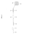
- a packing apparatus 350 is intended to fold the separator 311 supplied through the leading end of the transporting unit (not shown), after the separator 311 is laminated with the positive and negative electrode plates 102 and 104 by the lamination unit (not shown), so that the section of the separator 311 can have generally the shape of "Z", that is fold/fold fashion, as shown in FIG. 2, and to tape the folded separator 311 with a tape.
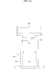
- FIGS. 3A and 3B are front and plan views of the packing apparatus shown in FIG. 1.
- the packing apparatus 350 comprises a frame 301, a base member 210 to which one batch of the separator 311 both surfaces of which have been laminated with a plurality of positive and negative electrode plates 102 and 104 in a predetermined pattern is supplied, and in which the one batch of the separator 311 is received, a stopper member 220 installed at the frame 301 to be raised and lowered so that the separator 311 received in the base member 210 can be prevented from being separated from the receiving rack 212, a folder member 230 continuously reciprocating to fold the separator 311 supplied to a receiving space 214 formed by the receiving rack 212 and the stopper member 220 so that the section of the separator 311 can have generally the shape of "Z", a cutting/taping member 240 for moving the separator 311 folded in the shape of "Z" to a predetermined taping position, for cutting a non-electrode-plate area of the separator 311 to which any electrode plate is not attached,
- the frame 301 may be divided into a lower frame at which a plurality of supporting pillars 309 for supporting the packing apparatus 350 apart from the floor are installed, and an upper frame on which components of the apparatus 350 are seated.
- Various driving motors, a vacuum system, an air system, an electronic system, an adhesive supplying system, and the like are provided at the lower frame. It is preferable that the upper surface of the upper frame is arranged to be in an accurately horizontal state.
- FIGS. 4A and 4B are expanded front and plan views of the portion of the base member of the packing apparatus.
- the base member 210 comprises a receiving rack 212 which has a planar shape and is installed at the base plate 216 installed at the frame 301, a guiding jaw 218 projected from the base plate 216 for guiding the supplied separator 311 toward the receiving rack 212, and a pair of recessed portions 211 recessed into both sides of the receiving rack 212. It is preferable that the upper surface of the guiding jaw 218 is disposed to be parallel to the travel path 313 and is specially surface-treated.
- the recessed portion 211 is a space into which a finger member 245 (FIGS. 6A and 6B) of the cutting/taping member 240 is inserted.
- the base member 210 further comprises a biasing member 213 for biasing the separator 311 toward the direction opposite to the separator supplied direction, that is, toward the stopper member 220 so that the separator 311 supplied to the receiving rack 212 can be easily folded to be almost the shape of "Z".
- the biasing member 213 comprises an air nozzle 215 capable of pushing the separator 311 fluttering due to air blowing force toward the stopper member 220.
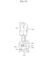
- FIGS. 5A and 5B are front and right side views of the stopper member and the folder member shown in FIG. 1.
- the stopper member 220 is installed to be capable of being moved linearly back and forth with respect to the frame 301 by a stopper moving member 222 which is installed at the frame 301 and is controlled by the control unit so that the stopper member 220 can block selectively a side of the base member 210 to form the receiving space and prevent the separator 311 supplied to the receiving rack 212 from being separated from the receiving rack 212. It is preferable that the stopper member 220 has two stopper forks 224 at its one end, and a vacant space is formed between the two stopper forks 224.
- the folder member 230 is intended to continuously press and fold the separator 311 supplied to the receiving space and biased toward the stopper member 220 so that the sections of the separator 311 at both side portions of the positive electrode plates 102 and the negative electrode plates 104 can have generally the shape of "Z", and to cause the positive electrode plates 102 and the negative electrode plates 104 alternate with each other.
- the folder member 230 comprises a folder plate 232 disposed to be raised or lowered at a position corresponding to the receiving space, and a folder cylinder 234 which is installed at the stopper member 220 and controlled by the control unit.
- the folder plate 232 moves back and forth as many times as the number of electrode plates required for a battery, that is, the number of the positive electrode plates and the negative electrode plates which alternate with each other.
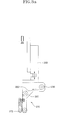
- the cutting/taping member 240 comprises a pair of clamp members 242 which approach both sides of the base member 210, clamp both sides of a piece of separator which is folded generally in the shape of "Z", and are moved horizontally to a taping position, a cutting member 250 (FIGS. 7A and 7B) installed at the frame 301 to be movable for cutting the separator 311 from above the base member 210 after the piece of separator 311 is moved by the clamp members 242, a tape supplying member 270 (FIG. 1 and FIG.
- clamp rotating members 280 installed at the frame 301 for rotating the clamp members 242 predetermined times so that the piece of separator can be taped while the piece of separator to which one end of the tape 262 is attached is rotated at both ends thereof
- a tape cutting member 290 (FIG.
- each clamp member 242 comprises a movable block 241 which is moved back and forth between the base member 210 and the taping position along an LM guide 246 and guide rails 248 which are parallel to the travel path of the separator 311, and a pair of finger members 245 installed at the movable block 241 so as to clamp the piece of separator 311 while being positioned at the recessed portion 211 and being operated by an air cylinder 243.
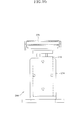
- the cutting member 250 is intended to cut the leading end of a non-attached area of the piece of separator 311 moved to the taping position by the clamp members 242, and comprises a heating cutter 258 which is provided with a heating wire 252.
- the heating cutter 258 is installed at one end of a cylinder 254 to be disposed over the travel path 313 so that the heating cutter 258 can be selectively moved toward the base member 210 by the cylinder 254 to contact the separator 311, and the heating wire 252 heated to a predetermined temperature can cut the separator 311.
- the cylinder 254 is supported by a bracket 252 which is installed at the frame 301.
- the tape supplying member 270 comprises a tape supplying roller 264 and a plurality of tape guiding rollers 266 which are installed at the frame 301, and a pair of tape attaching rollers 272 which are installed at one end of a cylinder 268 installed at the frame 301 to be raised or lowered by the cylinder 268 and are positioned on the travel path of the tape 262 so that one end of the tape 262 can selectively contact the upper surface of the separator 311.
- the holder member 244 is disposed to correspond to the tape attaching rollers 272.
- the holder member 242 is intended to prevent a non-attached area of the separator 311 from fluttering since the separator 311 is cut before a piece of separator 311 is taped, and, therefore, the fluttering occurs.
- the holder member 244 comprises a bracket 274 installed at the frame 301, and a holding roller 278 installed so as to be selectively raised and lowered by a cylinder 276 installed at a bracket 274 until the holding roller 278 contact the lower surface of the separator 311.
- each of the clamp rotating members 280 comprises a stepping motor 282 installed at the movable block 241 so that the axis of rotation of the stepping motor 282 can be coaxial with that of the finger members 245, and, therefore, the clamp rotating member 280 can rotate the finger members 245 with the rotational force thereof.
- the tape cutting member 290 is installed at the frame 301 to be close to the holder member 244 so that the tape cutting member 290 can be rotated by the clamp rotating member 280 (FIGS. 6A and 6B), and cut the loose end portion of the tape 262 (FIGS. 3A) extended from the packed piece of separator 311.
- the tape cutting member 290 comprises a bracket 292 installed at the frame 301, and a cutting body 296 having a cutting wire 295 for heating and cutting the tape 262, which is raised and lowered by a cylinder 294 which is installed at the bracket 292 and is operated below the travel path by the control unit.
- the power of the packing apparatus 350 is turned on, and data required for the control unit is set.
- the separator 311 both surfaces of which the positive and negative electrode plates 102 and 104 have been attached to in the predetermined pattern is prepared to be supplied via the travel path 313.
- the stopper member 220 is lowered to block both sides of the base member 210 and to form the receiving space 214 above the receiving rack 212.
- the separator 311 which was supplied by the transporting unit begins to be supplied to the receiving rack 212 of the base member 210 guided by the guiding jaw 218.
- the separator 311 is biased toward the stopper member 230 by the air blowing force generated by the air nozzle 215 of the biasing member 213.
- the folder plate 232 of the folder member 230 continuously presses the separator 311 supplied to the receiving space and biased by a predetermined times, and folds the separator 311 so that the sections of both sides of the separator 311 can have generally the shape of "Z", and the positive electrode plates 102 and the negative electrode plates 104 can alternate with each other.
- the stopper member 220 is raised in a state that the folder plate 232 presses a piece of separator 311 against the receiving rack 212.
- the clamp members 242 of the cutting/taping member 240 are caused to approach the both sides of the base member 210, and clamp both sides of the piece of separator 311 folded generally in the shape of "Z". Together with the clamping operation, the folder plate 232 is raised.
- the clamp members 242 are operated to move the piece of separator 311 horizontally to a taping position.
- the tape supplying member 270 is operated to cause the leading end of the tape 262 to adhere to the upper surface of the piece of separator 311 positioned at the taping position.
- the holder member 244 is raised to cause the holding roller 278 to contact the lower surface of the separator 311. Therefore, since the tape attaching rollers 272 and the holding roller 278 hold the separator 311, the separator 311 does not flutter.
- the cutting member 250 is lowered to cut the leading end of a non-attached area of the piece of separator 311. Then, the heating cutter 258 heated to a predetermined temperature cuts the separator 311.
- the clamp rotating members 280 are operated to tape the piece of separator 311. Then, the finger members 245 are rotated by the stepping motors 282, and, at the same time, the tape 262 supplied from the tape supplying member 270 is naturally wound around the piece of separator 311 to tape the piece of separator 311.
- the packing apparatus for an automated manufacturing system of a lithium secondary battery has the following advantages. First, the overall efficiency of production thereof can be enhanced due to the employment of the automated manufacturing system, and a rate of defective secondary batteries can be lowered.
Abstract
Description
- The present invention relates to a packing apparatus for an automated manufacturing system of a lithium secondary battery. In particular, but not exclusively, the present invention relates to a packing apparatus for use with an automated manufacturing system such as that described in the applicant's co-pending European patent application which claims priority from Korean patent application No. 2001-028493.
- In general, as portable electronic products such as video cameras, portable phones, and portable PCs become lighter, or highly functional, various development and research have been focused on batteries used as power sources of such portable electronic products. Such batteries can be used continuously by recharging the batteries.
- Among various batteries, usually, nickel cadmium batteries, nickel hydrogen batteries, nickel zinc batteries, lithium secondary batteries and the like are used as power sources of electronic products, and, in particular, lithium secondary batteries are generally used taking into consideration the use life and capacity thereof.
- According to types of electrolyte, the lithium secondary batteries are classified into lithium metal batteries and lithium ion batteries which employ liquid electrolyte, and lithium polymer batteries which employ solid polymer electrolyte. According to types of solid polymer electrolyte, the lithium polymer batteries are classified into full-solid type lithium polymer batteries in which organic electrolytic liquid is not included at all, and lithium ion polymer batteries employing gel type polymer electrolyte containing organic electrolytic liquid.
- The lithium secondary battery is manufactured by stacking a plurality of unit cells having a separator-electrode structure so as to meet a required capacity, connecting the unit cells to each other in parallel, and packing the unit cells into a cylindrical or polyhedral can.
- However, in a battery in which electrode plates are disposed according to a conventional method, there is a problem in which when the battery is overcharged, a voltage of the battery rises drastically, and the energy of the battery maybe instantaneously discharged and the electrolyte may evaporate or burn, and therefore the performance of the battery and safety thereof deteriorate. In addition, there is another problem in which the process of attaching electrode taps for electrically connecting unit cells to each other is very complicate.
- To solve the above-described problems, it is an objective of the present invention to provide a packing apparatus for an automated manufacturing system of a secondary battery having an improved structure which apparatus is capable of automating operations of folding a separator both surfaces of which are laminated with positive electrode plates and negative electrode plates in a continuous process line.
- Accordingly, to achieve the above objectives, there is provided a packing apparatus for an automated manufacturing system of a secondary lithium battery comprising: a frame; abase member which is installed at the frame, and is provided with a receiving rack for receiving a batch of separator both surfaces of which are laminated with positive electrode plates and negative electrode plates in a predetermined pattern; a stopper member installed at the frame to be linearly movable so as to selectively approach one end of the base member for preventing the separator being supplied to the base member from being separated from the receiving rack; a folder member installed at the frame to be linearly movable with respect to the receiving rack so that the folder can press the separator supplied to a receiving space formed by the receiving rack and the stopper member for predetermined duration, and fold the separator so that both side sections of the folded separator can have the shape of"Z", and the positive electrode plates and the negative electrode plates can alternate with each other; and a cutting/taping member for moving the separator folded in the shape of "Z" to a predetermined area, cutting the separator at a non-electrode plate area to which no electrode plate is attached, and taping the folded and cut piece of separator.
- Preferably, in the packing apparatus for an automated manufacturing system of a secondary lithium battery, the base member comprises: a guiding jaw projected from a base plate to guide the separator supplied thereto; and a pair of recessed portions recessed into both sides of the receiving rack.
- Preferably, in the packing apparatus for an automated manufacturing system of a secondary lithium battery, the base member further comprises a biasing member installed at the frame for biasing the separator toward the stopper member so that the separator supplied to the receiving rack can be easily folded in the shape of "Z".
- In the packing apparatus for an automated manufacturing system of a secondary lithium battery, it is preferable that the stopper member has a stopper fork for blocking both sides of the base member, and is linearly moved by a stopper moving member.
- Preferably, in the packing apparatus for an automated manufacturing system of a secondary lithium battery, the folder member comprises a folder plate moved by a folder moving member.
- Preferably, in the packing apparatus for an automated manufacturing system of a secondary lithium battery, the cutting/taping member comprises: a pair of clamp members for approaching both sides of the base member, clamping both sides of a piece of separator folded in the shape of "Z", and moving the piece of separator horizontally to a taping position; a cutting member installed at the frame to be movable for cutting the separator at the leading end of the base member after the separator has been moved by the clamp member; a tape supplying member installed at the frame to attach one end of tape to the piece of separator after a tape roller around which the tape is wound is moved along a tape travel path; clamp rotating members installed at the frame for rotating the clamp members predetermined times so that the piece of separator can be taped while the piece of separator to which one end of the tape is attached is rotated at both ends thereof; and a tape cutting member installed at the tape supplying member to be movable for cutting the loose end portion of the tape extended from the packed piece of separator which has been rotated by the clamp rotating members and has been packed with the tape.
- Preferably, in the packing apparatus for an automated manufacturing system of a secondary lithium battery, the cutting/taping member further comprises a holder member installed at the frame to be raised and lowered so that the holder member can approach the tape supplying member and contact one surface of the separator to prevent the separator from fluttering before the separator is cut by the cutting member.
- The invention will now be described, by way of example only, with reference to the accompanying drawings in which:
- FIG. 1 is a schematic perspective view illustrating a packing apparatus for an automated manufacturing system of a lithium secondary battery according to a preferred embodiment of the present invention;
- FIG. 2 is a front view illustrating an example in which the separator strip is folded generally in the shape of "Z" by the lamination unit shown in FIG. 1;
- FIGS. 3A and 3B are front and plan views of the packing apparatus shown in FIG. 1;
- FIGS. 4A and 4B are expanded front and plan views of a base member portion shown in FIG. 3;
- FIGS. 5A and 5B are front and right side views of a stopper member and a folder member shown in FIG. 3, respectively;
- FIGS. 6A and 6B are front and right side views of a clamp member portion shown in FIG. 3;
- FIGS. 7A and 7B are front and right side views of a cutting member portion shown in FIG. 3;
- FIGS. 8A and 8B are front and right side views of a tape supplying member portion shown in FIG. 3; and
- FIGS. 9A, 9B, and 9C are views of a holder member portion shown in FIG. 3.
-
- Referring to FIG. 1, a
packing apparatus 350 according to the present invention is intended to fold theseparator 311 supplied through the leading end of the transporting unit (not shown), after theseparator 311 is laminated with the positive andnegative electrode plates separator 311 can have generally the shape of "Z", that is fold/fold fashion, as shown in FIG. 2, and to tape the foldedseparator 311 with a tape. - The reader should refer to the applicant's co-pending European application referred to above for details of a suitable automated manufacturing system for a lithium secondary battery in which the packaging apparatus of the present application may be used, though it should be understood that the packaging apparatus is not limited to use in the system as disclosed therein.
- FIGS. 3A and 3B are front and plan views of the packing apparatus shown in FIG. 1.
- Referring to FIG. 1 and FIGS. 3A and 3B, the
packing apparatus 350 comprises aframe 301, abase member 210 to which one batch of theseparator 311 both surfaces of which have been laminated with a plurality of positive andnegative electrode plates separator 311 is received, astopper member 220 installed at theframe 301 to be raised and lowered so that theseparator 311 received in thebase member 210 can be prevented from being separated from the receivingrack 212, afolder member 230 continuously reciprocating to fold theseparator 311 supplied to areceiving space 214 formed by the receivingrack 212 and thestopper member 220 so that the section of theseparator 311 can have generally the shape of "Z", a cutting/taping member 240 for moving theseparator 311 folded in the shape of "Z" to a predetermined taping position, for cutting a non-electrode-plate area of theseparator 311 to which any electrode plate is not attached, and for taping thecut separator 311. - The
frame 301 may be divided into a lower frame at which a plurality of supportingpillars 309 for supporting thepacking apparatus 350 apart from the floor are installed, and an upper frame on which components of theapparatus 350 are seated. Various driving motors, a vacuum system, an air system, an electronic system, an adhesive supplying system, and the like are provided at the lower frame. It is preferable that the upper surface of the upper frame is arranged to be in an accurately horizontal state. - FIGS. 4A and 4B are expanded front and plan views of the portion of the base member of the packing apparatus.
- Referring to FIGS. 4A and 4B, the
base member 210 comprises a receivingrack 212 which has a planar shape and is installed at thebase plate 216 installed at theframe 301, a guidingjaw 218 projected from thebase plate 216 for guiding the suppliedseparator 311 toward the receivingrack 212, and a pair of recessedportions 211 recessed into both sides of the receivingrack 212. It is preferable that the upper surface of the guidingjaw 218 is disposed to be parallel to thetravel path 313 and is specially surface-treated. Therecessed portion 211 is a space into which a finger member 245 (FIGS. 6A and 6B) of the cutting/taping member 240 is inserted. - In addition, the
base member 210 further comprises abiasing member 213 for biasing theseparator 311 toward the direction opposite to the separator supplied direction, that is, toward thestopper member 220 so that theseparator 311 supplied to the receivingrack 212 can be easily folded to be almost the shape of "Z". It is preferable that thebiasing member 213 comprises anair nozzle 215 capable of pushing theseparator 311 fluttering due to air blowing force toward thestopper member 220. - FIGS. 5A and 5B are front and right side views of the stopper member and the folder member shown in FIG. 1.
- Referring to FIGS. 5A and 5B, the
stopper member 220 is installed to be capable of being moved linearly back and forth with respect to theframe 301 by astopper moving member 222 which is installed at theframe 301 and is controlled by the control unit so that thestopper member 220 can block selectively a side of thebase member 210 to form the receiving space and prevent theseparator 311 supplied to the receivingrack 212 from being separated from the receivingrack 212. It is preferable that thestopper member 220 has twostopper forks 224 at its one end, and a vacant space is formed between the twostopper forks 224. - The
folder member 230 is intended to continuously press and fold theseparator 311 supplied to the receiving space and biased toward thestopper member 220 so that the sections of theseparator 311 at both side portions of thepositive electrode plates 102 and thenegative electrode plates 104 can have generally the shape of "Z", and to cause thepositive electrode plates 102 and thenegative electrode plates 104 alternate with each other. Thefolder member 230 comprises afolder plate 232 disposed to be raised or lowered at a position corresponding to the receiving space, and afolder cylinder 234 which is installed at thestopper member 220 and controlled by the control unit. Therefore, during packing of a batch of theseparator 311, while thestopper member 220 moves back and forth once, thefolder plate 232 moves back and forth as many times as the number of electrode plates required for a battery, that is, the number of the positive electrode plates and the negative electrode plates which alternate with each other. - Referring to FIGS. 6A and 6B, the cutting/
taping member 240 comprises a pair ofclamp members 242 which approach both sides of thebase member 210, clamp both sides of a piece of separator which is folded generally in the shape of "Z", and are moved horizontally to a taping position, a cutting member 250 (FIGS. 7A and 7B) installed at theframe 301 to be movable for cutting theseparator 311 from above thebase member 210 after the piece ofseparator 311 is moved by theclamp members 242, a tape supplying member 270 (FIG. 1 and FIG. 3) installed at theframe 301 so as to attach one end of atape 262 to a piece ofseparator 311 after atape roller 264 around which thetape 262 is wound is moved to the taping position through a tape travel path, clamp rotating members 280 (FIGS. 6A and 6B) installed at theframe 301 for rotating theclamp members 242 predetermined times so that the piece of separator can be taped while the piece of separator to which one end of thetape 262 is attached is rotated at both ends thereof, a tape cutting member 290 (FIG. 3A) installed at theframe 301 to be movable for cutting the loose end portion of thetape 262 extended from the packed piece ofseparator 311 which has been rotated by theclamp rotating members 280 and has been packed with thetape 262, and aholder member 244 installed at theframe 301 to be raised and lowered so that theholder member 244 can approach thetape supplying member 270 and contact the lower surface of theseparator 311 to prevent theseparator 311 from fluttering before theseparator 311 is cut by the cuttingmember 250. - Referring to FIGS. 6A and 6B, the pair of
clamp members 242 are installed to be symmetrical with respect to the travel path of theseparator 311 and to be parallel to theframe 301. Eachclamp member 242 comprises amovable block 241 which is moved back and forth between thebase member 210 and the taping position along anLM guide 246 andguide rails 248 which are parallel to the travel path of theseparator 311, and a pair offinger members 245 installed at themovable block 241 so as to clamp the piece ofseparator 311 while being positioned at the recessedportion 211 and being operated by anair cylinder 243. - As shown in FIGS. 7A and 7B, the cutting
member 250 is intended to cut the leading end of a non-attached area of the piece ofseparator 311 moved to the taping position by theclamp members 242, and comprises aheating cutter 258 which is provided with aheating wire 252. Theheating cutter 258 is installed at one end of acylinder 254 to be disposed over thetravel path 313 so that theheating cutter 258 can be selectively moved toward thebase member 210 by thecylinder 254 to contact theseparator 311, and theheating wire 252 heated to a predetermined temperature can cut theseparator 311. Thecylinder 254 is supported by abracket 252 which is installed at theframe 301. - Referring to FIG. 1, FIG.3A and FIGS. 8A and 8B, the
tape supplying member 270 comprises atape supplying roller 264 and a plurality oftape guiding rollers 266 which are installed at theframe 301, and a pair oftape attaching rollers 272 which are installed at one end of acylinder 268 installed at theframe 301 to be raised or lowered by thecylinder 268 and are positioned on the travel path of thetape 262 so that one end of thetape 262 can selectively contact the upper surface of theseparator 311. - As shown in FIGS. 9A and 9B, the
holder member 244 is disposed to correspond to thetape attaching rollers 272. Theholder member 242 is intended to prevent a non-attached area of theseparator 311 from fluttering since theseparator 311 is cut before a piece ofseparator 311 is taped, and, therefore, the fluttering occurs. To this end, theholder member 244 comprises abracket 274 installed at theframe 301, and a holdingroller 278 installed so as to be selectively raised and lowered by acylinder 276 installed at abracket 274 until the holdingroller 278 contact the lower surface of theseparator 311. - As shown in FIG. 6A and 6B, each of the
clamp rotating members 280 comprises a steppingmotor 282 installed at themovable block 241 so that the axis of rotation of the steppingmotor 282 can be coaxial with that of thefinger members 245, and, therefore, theclamp rotating member 280 can rotate thefinger members 245 with the rotational force thereof.
As shown in FIGS. 9A and 9C, thetape cutting member 290 is installed at theframe 301 to be close to theholder member 244 so that thetape cutting member 290 can be rotated by the clamp rotating member 280 (FIGS. 6A and 6B), and cut the loose end portion of the tape 262 (FIGS. 3A) extended from the packed piece ofseparator 311. Thetape cutting member 290 comprises abracket 292 installed at theframe 301, and a cutting body 296 having acutting wire 295 for heating and cutting thetape 262, which is raised and lowered by acylinder 294 which is installed at thebracket 292 and is operated below the travel path by the control unit. - The operation of the packing apparatus for an automated manufacturing system of a lithium secondary battery configured as above according to a preferred embodiment of the present invention will be described.
- First, the power of the
packing apparatus 350 is turned on, and data required for the control unit is set. Then, theseparator 311 both surfaces of which the positive andnegative electrode plates travel path 313. In addition, thestopper member 220 is lowered to block both sides of thebase member 210 and to form the receivingspace 214 above thereceiving rack 212. - Subsequently, when a start button of the control unit is pressed, the
separator 311 which was supplied by the transporting unit begins to be supplied to thereceiving rack 212 of thebase member 210 guided by the guidingjaw 218. In this step, theseparator 311 is biased toward thestopper member 230 by the air blowing force generated by theair nozzle 215 of the biasingmember 213. - In this state, the
folder plate 232 of thefolder member 230 continuously presses theseparator 311 supplied to the receiving space and biased by a predetermined times, and folds theseparator 311 so that the sections of both sides of theseparator 311 can have generally the shape of "Z", and thepositive electrode plates 102 and thenegative electrode plates 104 can alternate with each other. Then, thestopper member 220 is raised in a state that thefolder plate 232 presses a piece ofseparator 311 against the receivingrack 212. Subsequently, theclamp members 242 of the cutting/tapingmember 240 are caused to approach the both sides of thebase member 210, and clamp both sides of the piece ofseparator 311 folded generally in the shape of "Z". Together with the clamping operation, thefolder plate 232 is raised. - Thereafter, the
clamp members 242 are operated to move the piece ofseparator 311 horizontally to a taping position. Subsequently, thetape supplying member 270 is operated to cause the leading end of thetape 262 to adhere to the upper surface of the piece ofseparator 311 positioned at the taping position. At the same time, theholder member 244 is raised to cause the holdingroller 278 to contact the lower surface of theseparator 311. Therefore, since thetape attaching rollers 272 and the holdingroller 278 hold theseparator 311, theseparator 311 does not flutter. - Subsequently, the cutting
member 250 is lowered to cut the leading end of a non-attached area of the piece ofseparator 311. Then, theheating cutter 258 heated to a predetermined temperature cuts theseparator 311. - Thereafter, while the piece of
separator 311 to which the leading end of thetape 262 is adhered is rotated at both ends thereof, theclamp rotating members 280 are operated to tape the piece ofseparator 311. Then, thefinger members 245 are rotated by the steppingmotors 282, and, at the same time, thetape 262 supplied from thetape supplying member 270 is naturally wound around the piece ofseparator 311 to tape the piece ofseparator 311. - Subsequently, the
tape cutting member 290 is operated to cut the loose end of thetape 262 extended from the taped piece ofseparator 311. Then, thecutting wire 295 is moved to cut thetape 262 by using heat, and the packing operation is finally completed.
As described above, the packing apparatus for an automated manufacturing system of a lithium secondary battery according to the present invention has the following advantages.
First, the overall efficiency of production thereof can be enhanced due to the employment of the automated manufacturing system, and a rate of defective secondary batteries can be lowered. - Second, since the separator both surfaces of which positive electrode plates and negative electrode plates are attached to, respectively, can be folded by serialized operations of the receiving rack, the stopper member, and the pressing plate so that both side sections of the folded separator can have generally the shape of "Z", productivity of secondary batteries can be enhanced markedly.
- Third, since folded pieces of separator can be continuously moved, and taped by automated robot equipments, productivity of secondary batteries and efficiency of manufacturing processes can be enhanced.
- While this invention has been particularly shown and described with reference to preferred embodiments thereof, it will be understood by those skilled in the art that various changes in form and details may be made therein without departing from the spirit and scope of the invention as defined by the appended claims.
Claims (7)
- A packing apparatus for an automated manufacturing system of a secondary lithium battery comprising:a frame;a base member which is provided with a receiving rack for receiving a batch of separator both surfaces of which are laminated with positive electrode plates and negative electrode plates in a predetermined pattern;a stopper member movable so as to selectively approach one end of the base member for preventing the separator being supplied to the base member from being separated from the receiving rack;a folder member movable with respect to the receiving rack so that the folder can press the separator supplied to a receiving space formed by the receiving rack and the stopper member for predetermined duration, and fold the separator so that both side sections of the folded separator can have generally the shape of "Z", and the positive electrode plates and the negative electrode plates can alternate with each other; anda cutting/taping member for moving the folded separator to a predetermined area, cutting the separator at a non-electrode area to which no electrode is attached, and taping the folded and cut piece of separator.
- A packing apparatus as claimed in claim 1, wherein the base member comprises:a guiding jaw projected from a base plate to guide the separator supplied thereto; and a pair of recessed portions recessed into both sides of the receiving rack.
- A packing apparatus as claimed in claim 1 or claim 2, wherein the base member further comprises a biasing member for biasing the separator toward the stopper member so that the separator supplied to the receiving rack can be easily folded.
- A packing apparatus as claimed in any previous claim, wherein the stopper member has a stopper fork for blocking both sides of the base member, and is linearly moved by a stopper moving member.
- A packing apparatus as claimed in any previous claim, wherein the folder member comprises a folder plate moved by a folder moving member.
- A packing apparatus as claimed in any previous claim, wherein the cutting/taping member comprises:a pair of clamp members for approaching both sides of the base member, clamping both sides of a piece of folded separator, and moving the piece of separator horizontally to a taping position;a cutting member movable for cutting the separator at the leading end of the base member after the separator has been moved by the clamp member;a tape supplying member adapted to attach one end of tape to the piece of separator after a tape roller around which the tape is wound is moved along a tape travel path;clamp rotating members for rotating the clamp members a predetermined number of times so that the piece of separator can be taped while the piece of separator to which one end of the tape is attached is rotated; anda tape cutting member for cutting a loose end portion of the tape extended from the packed piece of separator which has been rotated by the clamp rotating members and has been packed with the tape.
- A packing apparatus as claimed in claim 6, wherein the cutting/taping member further comprises a holder member adapted to be raised and lowered so that the holder member can approach the tape supplying member and contact one surface of the separator to prevent the separator from fluttering before the separator is cut by the cutting member.
Applications Claiming Priority (2)
| Application Number | Priority Date | Filing Date | Title |
|---|---|---|---|
| KR10-2001-0028495A KR100388650B1 (en) | 2001-05-23 | 2001-05-23 | Packing apparatus for automated manufacturing system of lithium secondary cell |
| KR2001028495 | 2001-05-23 |
Publications (3)
| Publication Number | Publication Date |
|---|---|
| EP1261061A2 true EP1261061A2 (en) | 2002-11-27 |
| EP1261061A3 EP1261061A3 (en) | 2004-01-14 |
| EP1261061B1 EP1261061B1 (en) | 2008-10-15 |
Family
ID=19709853
Family Applications (1)
| Application Number | Title | Priority Date | Filing Date |
|---|---|---|---|
| EP02253591A Expired - Lifetime EP1261061B1 (en) | 2001-05-23 | 2002-05-22 | Packing apparatus for an automated manufacturing system for a lithium secondary battery |
Country Status (8)
| Country | Link |
|---|---|
| US (1) | US7500304B2 (en) |
| EP (1) | EP1261061B1 (en) |
| JP (1) | JP4199008B2 (en) |
| KR (1) | KR100388650B1 (en) |
| CN (1) | CN1200474C (en) |
| AT (1) | ATE411627T1 (en) |
| DE (1) | DE60229323D1 (en) |
| WO (1) | WO2002095845A1 (en) |
Cited By (3)
| Publication number | Priority date | Publication date | Assignee | Title |
|---|---|---|---|---|
| CN102152876A (en) * | 2011-02-26 | 2011-08-17 | 东莞市鸿宝锂电科技有限公司 | Battery core shaping mechanism and fully-automatic battery core liquid-extracting, packaging and shaping packing machine |
| CN102229365A (en) * | 2011-04-12 | 2011-11-02 | 东华大学 | Packaging method and special packaging machine for negative plate |
| CN103600862A (en) * | 2013-11-25 | 2014-02-26 | 太原风华信息装备股份有限公司 | Laminated lithium battery pole group packing unit |
Families Citing this family (35)
| Publication number | Priority date | Publication date | Assignee | Title |
|---|---|---|---|---|
| US7927742B2 (en) | 2004-10-29 | 2011-04-19 | Medtronic, Inc. | Negative-limited lithium-ion battery |
| US9077022B2 (en) | 2004-10-29 | 2015-07-07 | Medtronic, Inc. | Lithium-ion battery |
| US8105714B2 (en) | 2004-10-29 | 2012-01-31 | Medtronic, Inc. | Lithium-ion battery |
| US8980453B2 (en) | 2008-04-30 | 2015-03-17 | Medtronic, Inc. | Formation process for lithium-ion batteries |
| CN101048898B (en) | 2004-10-29 | 2012-02-01 | 麦德托尼克公司 | Lithium-ion battery and medical device |
| US7662509B2 (en) | 2004-10-29 | 2010-02-16 | Medtronic, Inc. | Lithium-ion battery |
| US7563541B2 (en) | 2004-10-29 | 2009-07-21 | Medtronic, Inc. | Lithium-ion battery |
| US7337010B2 (en) | 2004-10-29 | 2008-02-26 | Medtronic, Inc. | Medical device having lithium-ion battery |
| US7582387B2 (en) * | 2004-10-29 | 2009-09-01 | Medtronic, Inc. | Lithium-ion battery |
| US7682745B2 (en) | 2004-10-29 | 2010-03-23 | Medtronic, Inc. | Medical device having lithium-ion battery |
| US9065145B2 (en) | 2004-10-29 | 2015-06-23 | Medtronic, Inc. | Lithium-ion battery |
| US7641992B2 (en) | 2004-10-29 | 2010-01-05 | Medtronic, Inc. | Medical device having lithium-ion battery |
| KR100821887B1 (en) * | 2006-11-17 | 2008-04-16 | 주식회사 한림포스텍 | Battery cell array jig, battery pack assembling apparatus with battery cell array jig and assembling method of battery pack using battery cell array jig |
| CN102059551B (en) * | 2010-11-04 | 2013-01-09 | 周俊雄 | Roof membrane pressing machine of lithium thionyl chloride battery |
| KR101287413B1 (en) | 2011-01-03 | 2013-07-19 | (주)열린기술 | Apparatus for wrapping stack of electrode plate |
| KR101358760B1 (en) * | 2011-01-06 | 2014-02-07 | 주식회사 엘지화학 | Automated apparatus and method for adhering side tape to cell |
| US9287580B2 (en) | 2011-07-27 | 2016-03-15 | Medtronic, Inc. | Battery with auxiliary electrode |
| US20130149560A1 (en) | 2011-12-09 | 2013-06-13 | Medtronic, Inc. | Auxiliary electrode for lithium-ion battery |
| CN103057952B (en) * | 2013-01-11 | 2015-05-20 | 浙江欧德申自动化设备有限公司 | Horizontal conveying structure of electrode group fixture of electrode group boxing device |
| US9246185B2 (en) | 2013-03-14 | 2016-01-26 | Sion Power Corporation | Electrochemical cell having a folded electrode and separator, battery including the same, and method of forming same |
| CN103187585B (en) * | 2013-03-22 | 2015-10-28 | 周俊雄 | A kind of three-in-one molding machine |
| JP2014238958A (en) * | 2013-06-07 | 2014-12-18 | オートモーティブエナジーサプライ株式会社 | Nonaqueous battery |
| CN104551587B (en) * | 2013-10-21 | 2019-04-19 | 新昌县城关宾立机械厂 | Battery-mounting device |
| CN105098253A (en) * | 2014-05-21 | 2015-11-25 | 东莞新能源科技有限公司 | Double-flanging device for soft package lithium-ion battery |
| DE102015108651A1 (en) * | 2015-06-01 | 2016-12-01 | Technische Universität Berlin | Method and device for z folding a web material |
| CN106428706B (en) * | 2016-12-14 | 2018-10-23 | 苏州猎奇智能设备有限公司 | Power lithium cell electric core packing apparatus |
| CN106742432B (en) * | 2017-01-17 | 2019-06-07 | 无锡托格尔科技有限公司 | A kind of lithium battery outer packing production line automation equipment |
| CN107187628B (en) * | 2017-06-18 | 2023-03-24 | 陈亮 | Pile up automatic packaging module of material |
| CN108832167B (en) * | 2018-06-15 | 2023-06-30 | 深圳市光大激光科技股份有限公司 | Conduction band mechanism and tape printer thereof |
| CN109167100B (en) * | 2018-10-17 | 2020-09-08 | 苏州因知成新能源有限公司 | Lithium battery rubber coating machine |
| US11637353B2 (en) | 2018-12-27 | 2023-04-25 | Sion Power Corporation | Electrodes, heaters, sensors, and associated articles and methods |
| US11322804B2 (en) | 2018-12-27 | 2022-05-03 | Sion Power Corporation | Isolatable electrodes and associated articles and methods |
| CN111092266B (en) * | 2019-12-11 | 2021-01-26 | 江苏普正精密科技有限公司 | Automatic laminating machine and laminating method for lithium battery pole piece |
| CN112918752B (en) * | 2020-11-30 | 2022-01-21 | 昆山鸿仕达智能科技有限公司 | Film coating device and automatic film coating machine |
| FR3122607A1 (en) * | 2022-08-18 | 2022-11-11 | Verkor | Method of manufacturing a battery cell |
Citations (2)
| Publication number | Priority date | Publication date | Assignee | Title |
|---|---|---|---|---|
| US5667909A (en) * | 1995-06-23 | 1997-09-16 | Power Conversion, Inc. | Electrodes configured for high energy density galvanic cells |
| WO2000017950A1 (en) * | 1998-09-24 | 2000-03-30 | Thomas & Betts International, Inc. | Improved process for manufacturing electrochemical cells |
Family Cites Families (20)
| Publication number | Priority date | Publication date | Assignee | Title |
|---|---|---|---|---|
| US1678319A (en) * | 1925-01-14 | 1928-07-24 | Automatic Electric Inc | Punching die |
| US2085079A (en) * | 1936-06-19 | 1937-06-29 | Bell Telephone Labor Inc | Cutting device |
| US2350238A (en) * | 1942-07-25 | 1944-05-30 | Geo Knight & Co | Machine for trimming the flash from rubber heels and the like |
| US3355975A (en) * | 1965-03-08 | 1967-12-05 | Basic Products Inc | Apparatus for notching a disc |
| US3706249A (en) * | 1970-03-30 | 1972-12-19 | Xetca Inc | Programmed control system for punching machine |
| US3906826A (en) * | 1974-03-29 | 1975-09-23 | Bmr Enterprises | Workpiece indexing apparatus for machine tools |
| US4592739A (en) * | 1982-01-20 | 1986-06-03 | Idemitsu Petrochemical Co., Ltd. | Web material folding device |
| DE3614655A1 (en) * | 1986-04-30 | 1987-11-05 | Goebel Gmbh Maschf | DEVICE FOR DEPOSITING PRODUCTS |
| JPH03230479A (en) * | 1989-10-31 | 1991-10-14 | Japan Storage Battery Co Ltd | Stacking device for storage battery electrode plate |
| JPH04167371A (en) * | 1990-10-29 | 1992-06-15 | Yuasa Corp | Method and device for producing group of electrode plate for storage battery |
| JPH04355063A (en) * | 1991-05-30 | 1992-12-09 | Yuasa Corp | Method and device for piling up plate for storage battery |
| US5797306A (en) * | 1995-05-01 | 1998-08-25 | Marathon Electric Mfg. Corp. | Lamination notching apparatus |
| JPH10261422A (en) | 1997-03-17 | 1998-09-29 | Sony Corp | Tape sticking device |
| JPH10321259A (en) | 1997-05-15 | 1998-12-04 | Fuji Photo Film Co Ltd | Assembling method and system of battery |
| KR100223356B1 (en) * | 1997-06-28 | 1999-10-15 | 하기호 | Auto cell stacker system |
| JP3457858B2 (en) | 1997-09-26 | 2003-10-20 | 東芝電池株式会社 | Equipment for manufacturing electrode elements for lithium polymer batteries |
| US6000139A (en) * | 1998-03-06 | 1999-12-14 | Y & H Industrial Limited | Paper punch |
| JPH11260673A (en) * | 1998-03-16 | 1999-09-24 | Kansai Coke & Chem Co Ltd | Electrode laminate for electric double layer capacitor |
| JP2000001261A (en) * | 1998-06-16 | 2000-01-07 | Mitsubishi Heavy Ind Ltd | Automatic stacking device |
| KR100388648B1 (en) * | 2001-05-23 | 2003-06-25 | 주식회사 코캄엔지니어링 | Automated manufacturing system of lithium secondary cell |
-
2001
- 2001-05-23 KR KR10-2001-0028495A patent/KR100388650B1/en active IP Right Grant
-
2002
- 2002-05-17 US US10/478,540 patent/US7500304B2/en active Active
- 2002-05-17 WO PCT/KR2002/000934 patent/WO2002095845A1/en active Application Filing
- 2002-05-17 JP JP2002592210A patent/JP4199008B2/en not_active Expired - Lifetime
- 2002-05-22 EP EP02253591A patent/EP1261061B1/en not_active Expired - Lifetime
- 2002-05-22 AT AT02253591T patent/ATE411627T1/en not_active IP Right Cessation
- 2002-05-22 DE DE60229323T patent/DE60229323D1/en not_active Expired - Lifetime
- 2002-05-22 CN CNB021203148A patent/CN1200474C/en not_active Expired - Lifetime
Patent Citations (2)
| Publication number | Priority date | Publication date | Assignee | Title |
|---|---|---|---|---|
| US5667909A (en) * | 1995-06-23 | 1997-09-16 | Power Conversion, Inc. | Electrodes configured for high energy density galvanic cells |
| WO2000017950A1 (en) * | 1998-09-24 | 2000-03-30 | Thomas & Betts International, Inc. | Improved process for manufacturing electrochemical cells |
Non-Patent Citations (1)
| Title |
|---|
| PATENT ABSTRACTS OF JAPAN vol. 1998, no. 14, 31 December 1998 (1998-12-31) & JP 10 261422 A (SONY CORP), 29 September 1998 (1998-09-29) * |
Cited By (5)
| Publication number | Priority date | Publication date | Assignee | Title |
|---|---|---|---|---|
| CN102152876A (en) * | 2011-02-26 | 2011-08-17 | 东莞市鸿宝锂电科技有限公司 | Battery core shaping mechanism and fully-automatic battery core liquid-extracting, packaging and shaping packing machine |
| CN102152876B (en) * | 2011-02-26 | 2013-03-20 | 东莞市鸿宝锂电科技有限公司 | Battery core shaping mechanism and fully-automatic battery core liquid-extracting, packaging and shaping packing machine |
| CN102229365A (en) * | 2011-04-12 | 2011-11-02 | 东华大学 | Packaging method and special packaging machine for negative plate |
| CN102229365B (en) * | 2011-04-12 | 2012-11-07 | 东华大学 | Packaging method and special packaging machine for negative plate |
| CN103600862A (en) * | 2013-11-25 | 2014-02-26 | 太原风华信息装备股份有限公司 | Laminated lithium battery pole group packing unit |
Also Published As
| Publication number | Publication date |
|---|---|
| JP4199008B2 (en) | 2008-12-17 |
| EP1261061A3 (en) | 2004-01-14 |
| EP1261061B1 (en) | 2008-10-15 |
| WO2002095845A1 (en) | 2002-11-28 |
| ATE411627T1 (en) | 2008-10-15 |
| CN1386674A (en) | 2002-12-25 |
| CN1200474C (en) | 2005-05-04 |
| JP2004522278A (en) | 2004-07-22 |
| US20040168307A1 (en) | 2004-09-02 |
| DE60229323D1 (en) | 2008-11-27 |
| US7500304B2 (en) | 2009-03-10 |
| KR100388650B1 (en) | 2003-06-25 |
| KR20020089718A (en) | 2002-11-30 |
Similar Documents
| Publication | Publication Date | Title |
|---|---|---|
| EP1261061B1 (en) | Packing apparatus for an automated manufacturing system for a lithium secondary battery | |
| US7055570B2 (en) | Automated manufacturing system of lithium secondary battery | |
| KR100305350B1 (en) | assembling machine for negative electrode plate of Ni-MH battery and assembling process therefor | |
| EP2560223B1 (en) | Tape application apparatus and method for applying electrically non-conductive tape to a battery cell | |
| KR20170117681A (en) | Taping Apparatus Capable of Attaching Adhesive Tape to Battery Cell | |
| EP3054501B1 (en) | Apparatus for bonding separators in electrical devices | |
| JP4786342B2 (en) | Apparatus and method for stacking polymer battery combination | |
| EP1261062B1 (en) | Lamination apparatus for an automated manufacturing system for a lithium secondary battery | |
| EP1261063B1 (en) | Automated manufacturing system for manufacturing a secondary lithium battery | |
| US11223062B2 (en) | Stack holding apparatus | |
| EP4354566A1 (en) | Electrode assembly manufacturing device and manufacturing method | |
| KR200244344Y1 (en) | Packing apparatus for automated manufacturing system of lithium secondary cell | |
| JP5393139B2 (en) | Secondary battery manufacturing method and secondary battery manufacturing apparatus | |
| KR200244341Y1 (en) | Automated manufacturing system of lithium secondary cell | |
| EP4345962A1 (en) | Method for manufacturing battery | |
| JP3764398B2 (en) | Method and apparatus for manufacturing electric double layer capacitor cell | |
| CN220364139U (en) | Inverted battery bottom surface film sticking equipment | |
| KR102410892B1 (en) | System for manufaturing the lead tab | |
| KR20230090115A (en) | Electrode plate bonding device of pouch-type primary battery | |
| KR20230055079A (en) | Manufacturing device for electrode assembly and method using the same | |
| KR20240035350A (en) | Method of manufacturing battery |
Legal Events
| Date | Code | Title | Description |
|---|---|---|---|
| PUAI | Public reference made under article 153(3) epc to a published international application that has entered the european phase |
Free format text: ORIGINAL CODE: 0009012 |
|
| AK | Designated contracting states |
Kind code of ref document: A2 Designated state(s): AT BE CH CY DE DK ES FI FR GB GR IE IT LI LU MC NL PT SE TR |
|
| AX | Request for extension of the european patent |
Free format text: AL;LT;LV;MK;RO;SI |
|
| PUAL | Search report despatched |
Free format text: ORIGINAL CODE: 0009013 |
|
| AK | Designated contracting states |
Kind code of ref document: A3 Designated state(s): AT BE CH CY DE DK ES FI FR GB GR IE IT LI LU MC NL PT SE TR |
|
| AX | Request for extension of the european patent |
Extension state: AL LT LV MK RO SI |
|
| 17P | Request for examination filed |
Effective date: 20040426 |
|
| AKX | Designation fees paid |
Designated state(s): AT BE CH CY DE DK ES FI FR GB GR IE IT LI LU MC NL PT SE TR |
|
| RAP1 | Party data changed (applicant data changed or rights of an application transferred) |
Owner name: EAGLEPICHER KOKAM CO., LTD. |
|
| RAP1 | Party data changed (applicant data changed or rights of an application transferred) |
Owner name: KOKAM CO., LTD. |
|
| GRAP | Despatch of communication of intention to grant a patent |
Free format text: ORIGINAL CODE: EPIDOSNIGR1 |
|
| GRAS | Grant fee paid |
Free format text: ORIGINAL CODE: EPIDOSNIGR3 |
|
| GRAA | (expected) grant |
Free format text: ORIGINAL CODE: 0009210 |
|
| AK | Designated contracting states |
Kind code of ref document: B1 Designated state(s): AT BE CH CY DE DK ES FI FR GB GR IE IT LI LU MC NL PT SE TR |
|
| REG | Reference to a national code |
Ref country code: CH Ref legal event code: EP Ref country code: GB Ref legal event code: FG4D |
|
| REG | Reference to a national code |
Ref country code: CH Ref legal event code: NV Representative=s name: SERVOPATENT GMBH |
|
| REG | Reference to a national code |
Ref country code: IE Ref legal event code: FG4D |
|
| REF | Corresponds to: |
Ref document number: 60229323 Country of ref document: DE Date of ref document: 20081127 Kind code of ref document: P |
|
| PG25 | Lapsed in a contracting state [announced via postgrant information from national office to epo] |
Ref country code: AT Free format text: LAPSE BECAUSE OF FAILURE TO SUBMIT A TRANSLATION OF THE DESCRIPTION OR TO PAY THE FEE WITHIN THE PRESCRIBED TIME-LIMIT Effective date: 20081015 Ref country code: ES Free format text: LAPSE BECAUSE OF FAILURE TO SUBMIT A TRANSLATION OF THE DESCRIPTION OR TO PAY THE FEE WITHIN THE PRESCRIBED TIME-LIMIT Effective date: 20090126 |
|
| PG25 | Lapsed in a contracting state [announced via postgrant information from national office to epo] |
Ref country code: FI Free format text: LAPSE BECAUSE OF FAILURE TO SUBMIT A TRANSLATION OF THE DESCRIPTION OR TO PAY THE FEE WITHIN THE PRESCRIBED TIME-LIMIT Effective date: 20081015 Ref country code: PT Free format text: LAPSE BECAUSE OF FAILURE TO SUBMIT A TRANSLATION OF THE DESCRIPTION OR TO PAY THE FEE WITHIN THE PRESCRIBED TIME-LIMIT Effective date: 20090316 |
|
| PG25 | Lapsed in a contracting state [announced via postgrant information from national office to epo] |
Ref country code: BE Free format text: LAPSE BECAUSE OF FAILURE TO SUBMIT A TRANSLATION OF THE DESCRIPTION OR TO PAY THE FEE WITHIN THE PRESCRIBED TIME-LIMIT Effective date: 20081015 Ref country code: DK Free format text: LAPSE BECAUSE OF FAILURE TO SUBMIT A TRANSLATION OF THE DESCRIPTION OR TO PAY THE FEE WITHIN THE PRESCRIBED TIME-LIMIT Effective date: 20081015 |
|
| PLBE | No opposition filed within time limit |
Free format text: ORIGINAL CODE: 0009261 |
|
| STAA | Information on the status of an ep patent application or granted ep patent |
Free format text: STATUS: NO OPPOSITION FILED WITHIN TIME LIMIT |
|
| PG25 | Lapsed in a contracting state [announced via postgrant information from national office to epo] |
Ref country code: SE Free format text: LAPSE BECAUSE OF FAILURE TO SUBMIT A TRANSLATION OF THE DESCRIPTION OR TO PAY THE FEE WITHIN THE PRESCRIBED TIME-LIMIT Effective date: 20090115 |
|
| 26N | No opposition filed |
Effective date: 20090716 |
|
| PG25 | Lapsed in a contracting state [announced via postgrant information from national office to epo] |
Ref country code: MC Free format text: LAPSE BECAUSE OF NON-PAYMENT OF DUE FEES Effective date: 20090531 |
|
| PG25 | Lapsed in a contracting state [announced via postgrant information from national office to epo] |
Ref country code: IE Free format text: LAPSE BECAUSE OF NON-PAYMENT OF DUE FEES Effective date: 20090522 |
|
| PG25 | Lapsed in a contracting state [announced via postgrant information from national office to epo] |
Ref country code: GR Free format text: LAPSE BECAUSE OF FAILURE TO SUBMIT A TRANSLATION OF THE DESCRIPTION OR TO PAY THE FEE WITHIN THE PRESCRIBED TIME-LIMIT Effective date: 20090116 |
|
| PG25 | Lapsed in a contracting state [announced via postgrant information from national office to epo] |
Ref country code: LU Free format text: LAPSE BECAUSE OF NON-PAYMENT OF DUE FEES Effective date: 20090522 |
|
| PG25 | Lapsed in a contracting state [announced via postgrant information from national office to epo] |
Ref country code: TR Free format text: LAPSE BECAUSE OF FAILURE TO SUBMIT A TRANSLATION OF THE DESCRIPTION OR TO PAY THE FEE WITHIN THE PRESCRIBED TIME-LIMIT Effective date: 20081015 |
|
| PG25 | Lapsed in a contracting state [announced via postgrant information from national office to epo] |
Ref country code: CY Free format text: LAPSE BECAUSE OF FAILURE TO SUBMIT A TRANSLATION OF THE DESCRIPTION OR TO PAY THE FEE WITHIN THE PRESCRIBED TIME-LIMIT Effective date: 20081015 |
|
| REG | Reference to a national code |
Ref country code: FR Ref legal event code: PLFP Year of fee payment: 15 |
|
| REG | Reference to a national code |
Ref country code: FR Ref legal event code: PLFP Year of fee payment: 16 |
|
| REG | Reference to a national code |
Ref country code: FR Ref legal event code: PLFP Year of fee payment: 17 |
|
| PGFP | Annual fee paid to national office [announced via postgrant information from national office to epo] |
Ref country code: GB Payment date: 20190321 Year of fee payment: 18 |
|
| PGFP | Annual fee paid to national office [announced via postgrant information from national office to epo] |
Ref country code: NL Payment date: 20190321 Year of fee payment: 18 |
|
| PGFP | Annual fee paid to national office [announced via postgrant information from national office to epo] |
Ref country code: CH Payment date: 20190408 Year of fee payment: 18 |
|
| REG | Reference to a national code |
Ref country code: CH Ref legal event code: PCAR Free format text: NEW ADDRESS: WANNERSTRASSE 9/1, 8045 ZUERICH (CH) |
|
| REG | Reference to a national code |
Ref country code: NL Ref legal event code: MM Effective date: 20200601 |
|
| PG25 | Lapsed in a contracting state [announced via postgrant information from national office to epo] |
Ref country code: CH Free format text: LAPSE BECAUSE OF NON-PAYMENT OF DUE FEES Effective date: 20200531 Ref country code: LI Free format text: LAPSE BECAUSE OF NON-PAYMENT OF DUE FEES Effective date: 20200531 |
|
| PG25 | Lapsed in a contracting state [announced via postgrant information from national office to epo] |
Ref country code: NL Free format text: LAPSE BECAUSE OF NON-PAYMENT OF DUE FEES Effective date: 20200601 |
|
| GBPC | Gb: european patent ceased through non-payment of renewal fee |
Effective date: 20200522 |
|
| PG25 | Lapsed in a contracting state [announced via postgrant information from national office to epo] |
Ref country code: GB Free format text: LAPSE BECAUSE OF NON-PAYMENT OF DUE FEES Effective date: 20200522 |
|
| PGFP | Annual fee paid to national office [announced via postgrant information from national office to epo] |
Ref country code: FR Payment date: 20210324 Year of fee payment: 20 |
|
| PGFP | Annual fee paid to national office [announced via postgrant information from national office to epo] |
Ref country code: IT Payment date: 20210512 Year of fee payment: 20 Ref country code: DE Payment date: 20210322 Year of fee payment: 20 |
|
| REG | Reference to a national code |
Ref country code: DE Ref legal event code: R071 Ref document number: 60229323 Country of ref document: DE |