EP1260976A2 - Magneto-optisches Aufzeichnungmedium - Google Patents
Magneto-optisches Aufzeichnungmedium Download PDFInfo
- Publication number
- EP1260976A2 EP1260976A2 EP01122802A EP01122802A EP1260976A2 EP 1260976 A2 EP1260976 A2 EP 1260976A2 EP 01122802 A EP01122802 A EP 01122802A EP 01122802 A EP01122802 A EP 01122802A EP 1260976 A2 EP1260976 A2 EP 1260976A2
- Authority
- EP
- European Patent Office
- Prior art keywords
- magnetic layer
- layer
- magneto
- recording medium
- optical recording
- Prior art date
- Legal status (The legal status is an assumption and is not a legal conclusion. Google has not performed a legal analysis and makes no representation as to the accuracy of the status listed.)
- Withdrawn
Links
Images




Classifications
-
- G—PHYSICS
- G11—INFORMATION STORAGE
- G11B—INFORMATION STORAGE BASED ON RELATIVE MOVEMENT BETWEEN RECORD CARRIER AND TRANSDUCER
- G11B11/00—Recording on or reproducing from the same record carrier wherein for these two operations the methods are covered by different main groups of groups G11B3/00 - G11B7/00 or by different subgroups of group G11B9/00; Record carriers therefor
- G11B11/10—Recording on or reproducing from the same record carrier wherein for these two operations the methods are covered by different main groups of groups G11B3/00 - G11B7/00 or by different subgroups of group G11B9/00; Record carriers therefor using recording by magnetic means or other means for magnetisation or demagnetisation of a record carrier, e.g. light induced spin magnetisation; Demagnetisation by thermal or stress means in the presence or not of an orienting magnetic field
- G11B11/105—Recording on or reproducing from the same record carrier wherein for these two operations the methods are covered by different main groups of groups G11B3/00 - G11B7/00 or by different subgroups of group G11B9/00; Record carriers therefor using recording by magnetic means or other means for magnetisation or demagnetisation of a record carrier, e.g. light induced spin magnetisation; Demagnetisation by thermal or stress means in the presence or not of an orienting magnetic field using a beam of light or a magnetic field for recording by change of magnetisation and a beam of light for reproducing, i.e. magneto-optical, e.g. light-induced thermomagnetic recording, spin magnetisation recording, Kerr or Faraday effect reproducing
- G11B11/10582—Record carriers characterised by the selection of the material or by the structure or form
- G11B11/10586—Record carriers characterised by the selection of the material or by the structure or form characterised by the selection of the material
- G11B11/10589—Details
- G11B11/10593—Details for improving read-out properties, e.g. polarisation of light
-
- G—PHYSICS
- G11—INFORMATION STORAGE
- G11B—INFORMATION STORAGE BASED ON RELATIVE MOVEMENT BETWEEN RECORD CARRIER AND TRANSDUCER
- G11B11/00—Recording on or reproducing from the same record carrier wherein for these two operations the methods are covered by different main groups of groups G11B3/00 - G11B7/00 or by different subgroups of group G11B9/00; Record carriers therefor
- G11B11/10—Recording on or reproducing from the same record carrier wherein for these two operations the methods are covered by different main groups of groups G11B3/00 - G11B7/00 or by different subgroups of group G11B9/00; Record carriers therefor using recording by magnetic means or other means for magnetisation or demagnetisation of a record carrier, e.g. light induced spin magnetisation; Demagnetisation by thermal or stress means in the presence or not of an orienting magnetic field
- G11B11/105—Recording on or reproducing from the same record carrier wherein for these two operations the methods are covered by different main groups of groups G11B3/00 - G11B7/00 or by different subgroups of group G11B9/00; Record carriers therefor using recording by magnetic means or other means for magnetisation or demagnetisation of a record carrier, e.g. light induced spin magnetisation; Demagnetisation by thermal or stress means in the presence or not of an orienting magnetic field using a beam of light or a magnetic field for recording by change of magnetisation and a beam of light for reproducing, i.e. magneto-optical, e.g. light-induced thermomagnetic recording, spin magnetisation recording, Kerr or Faraday effect reproducing
- G11B11/10502—Recording on or reproducing from the same record carrier wherein for these two operations the methods are covered by different main groups of groups G11B3/00 - G11B7/00 or by different subgroups of group G11B9/00; Record carriers therefor using recording by magnetic means or other means for magnetisation or demagnetisation of a record carrier, e.g. light induced spin magnetisation; Demagnetisation by thermal or stress means in the presence or not of an orienting magnetic field using a beam of light or a magnetic field for recording by change of magnetisation and a beam of light for reproducing, i.e. magneto-optical, e.g. light-induced thermomagnetic recording, spin magnetisation recording, Kerr or Faraday effect reproducing characterised by the transducing operation to be executed
- G11B11/10515—Reproducing
-
- Y—GENERAL TAGGING OF NEW TECHNOLOGICAL DEVELOPMENTS; GENERAL TAGGING OF CROSS-SECTIONAL TECHNOLOGIES SPANNING OVER SEVERAL SECTIONS OF THE IPC; TECHNICAL SUBJECTS COVERED BY FORMER USPC CROSS-REFERENCE ART COLLECTIONS [XRACs] AND DIGESTS
- Y10—TECHNICAL SUBJECTS COVERED BY FORMER USPC
- Y10T—TECHNICAL SUBJECTS COVERED BY FORMER US CLASSIFICATION
- Y10T428/00—Stock material or miscellaneous articles
- Y10T428/24—Structurally defined web or sheet [e.g., overall dimension, etc.]
- Y10T428/24942—Structurally defined web or sheet [e.g., overall dimension, etc.] including components having same physical characteristic in differing degree
-
- Y—GENERAL TAGGING OF NEW TECHNOLOGICAL DEVELOPMENTS; GENERAL TAGGING OF CROSS-SECTIONAL TECHNOLOGIES SPANNING OVER SEVERAL SECTIONS OF THE IPC; TECHNICAL SUBJECTS COVERED BY FORMER USPC CROSS-REFERENCE ART COLLECTIONS [XRACs] AND DIGESTS
- Y10—TECHNICAL SUBJECTS COVERED BY FORMER USPC
- Y10T—TECHNICAL SUBJECTS COVERED BY FORMER US CLASSIFICATION
- Y10T428/00—Stock material or miscellaneous articles
- Y10T428/31—Surface property or characteristic of web, sheet or block
Definitions
- the present invention relates to a magneto-optical recording medium, and particularly to a magneto-optical recording medium which can perform magnetically induced super resolution reproduction.
- a magneto-optical recording medium which is provided with a recording mark having a mark length shorter than a spot diameter of a laser beam and formed at a period shorter than the spot diameter.
- a magnetically induced super resolution (MSR) reproduction method is proposed as a method of reproducing a recording mark smaller than a spot diameter of a beam.
- a laser light for reproduction is irradiated while a magneto-optical disk in which a plurality of magnetic layers including a recording layer and a reproduction layer are stacked is rotated, so that a temperature distribution is produced in a circumferential direction of the magneto-optical disk, and a small recording mark is read out by using this temperature distribution.
- resolution equivalent to the case where reproduction is substantially made with a light spot smaller than a spot diameter of the reproduction laser light can be obtained.
- a magnetically induced super resolution medium constituted by three magnetic layers having predetermined characteristics is disclosed in Japanese Patent Unexamined Publication No. 2000-200448.
- This medium is constituted by three magnetic layers of a reproduction layer, an intermediate layer, and a recording layer, and is a double mask magnetically induced super resolution medium (Double mask Rear Aperture Detection: D-RAD medium) in which a low temperature mask (called a front mask) is formed in a low temperature region of a temperature distribution formed in a beam spot, and a high temperature mask (called a rear mask) is formed in a high temperature region.
- a low temperature mask called a front mask
- a high temperature mask called a rear mask
- a recording mark having a length of 0.38 ⁇ m and formed on a land substrate of a track pitch of 0.9 ⁇ m can be reproduced by a reproduction magnetic field of 300 Oe or less.
- the land groove substrate is applied to the D-RAD medium, if it is a high density medium of about 2.3 GB/3.5 inches, it is possible to form a medium in which cross talk from an adjacent track is hardly generated.
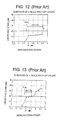
- FIG. 12 and FIG. 13 are graphs each explaining the dependency of cross talk of a conventional D-RAD medium upon reproduction power (Pr).
- the vertical axis indicates a decibel value CNR (dB) equivalent to the amount of generated cross talk, and the horizontal axis indicates a reproduction power (mW).
- FIG. 12 relates to a land groove substrate of a track pitch of 0.65 ⁇ m
- FIG. 13 relates to a land groove substrate of a track pitch of 0.50 ⁇ m.
- the cross talk exceeds 20 dB when the reproduction power Pr is approximately 4.5 mW.
- the reproduction power margin is decreased to about ⁇ 9.0 %.
- FIG. 14 is an explanatory view of magnetization states of the respective layers at the time of reproduction of a conventional D-RAD medium.
- FIG. 14 shows the directions of magnetization of a reproduction layer 51, an intermediate layer 52, and a recording layer 53 as three magnetic layers of the D-RAD medium.
- FIG. 14 shows the magnetization states in the vicinity of a beam spot BS where the light beam is irradiated, and in the case where this medium is moved in the upper right direction in the drawing, a temperature distribution in the beam spot is divided into three regions (a low temperature region A, an intermediate temperature region B, and a high temperature region C).
- the up direction indicates a recording direction L1
- the down direction indicates an erasing direction L2.
- the magnetization direction of the recording mark transferred to the reproduction layer 51 is the recording direction L1. That is, in this case, the magnetization direction in the intermediate temperature region B is directed in the same direction as the high temperature mask C1.
- FIGS. 15(a) and 15(b) are views for explaining a state of generation of cross talk in the case where the D-RAD medium is seen from above.
- FIG. 15(b) shows the case where a track pitch TP is relatively wide, and the high temperature mask C1 in the beam spot BS does not overlap an adjacent recording mark M1, so that the cross talk is not generated.
- the recording marks M1 which must be naturally masked are connected to each other and transfer is performed to make the directions uniform in the same magnetization direction L1 as the high temperature mask C1, and this has, as a cross talk signal, an effect on the reproduction of a recording mark of an adjacent track.
- the mark of the adjacent track is transferred by the following principle.
- a leakage magnetic field 63 is generated in the direction indicated by a slant arrow in the drawing. This is the same as the magnetization direction of the intermediate layer 52 in the intermediate temperature region B at the time of the transfer state, and acts in the direction to facilitate the transfer.
- the leakage magnetic field 63 is generated to become high in proportion to the intensity of the magnetization of the reproduction layer 51 and becomes weak in inverse proportion to the square of the distance.
- the reproduction layer 51 of the D-RAD medium uses a material in which the value of saturation magnetization increases in proportion to the temperature up to about 200°C, it is conceivable that as the mask of the high temperature region C is formed and approaches the recording mark M1 of the adjacent track, the leakage magnetic field 63 from the mask of the reproduction layer 51 of the high temperature region C acts in the direction to facilitate the transfer, and as shown in FIG. 17, it has an effect as cross talk on the adjacent track.
- the magneto-optical recording medium includes at least three magnetic layers of a first magnetic layer, a second magnetic layer and a third magnetic layer, in which a recording mark recorded in the third magnetic layer by irradiation of a light beam is transferred through the second magnetic layer as formed above the third magnetic layer to the first magnetic layer formed above the second magnetic layer for reproduction, wherein the first magnetic layer includes a high temperature mask having no spontaneous magnetization in a region where its temperature becomes a predetermined temperature or higher.
- cross talk from an adjacent track can be reduced, and recording noise and erase noise can be reduced even if a track pitch is made narrower than a conventional medium.
- the present invention provides a magneto-optical recording medium in which cross talk to an adjacent track can be reduced, even in the case where a track pitch is made narrower than a conventional D-RAD medium, and the generation of a magnetic noise resulting from the formation of a high temperature mask is suppressed because spontaneous magnetization does not exist at a high temperature.
- the high temperature mask having no spontaneous magnetization is formed.
- a magnetic material capable of adjusting the Curie temperature and the compensation temperature of the first magnetic layer is used as the metal.
- the metal is one of Cr, Mn, MnCr and Nb.
- a material such as glass or polycarbonate (PC) resin can be used for a substrate. It is preferable that an under layer is formed on the substrate, and the under layer is a dielectric layer made of a material having properties of enhancement of a Kerr rotation angle, and especially, a material such as SiN or AlN can be used.
- the first magnetic layer a material which mainly contains GdFeCo and is added with a metal material such as Cr or Mn, can be used.
- the second magnetic layer a material which mainly contains GdFeCo or GdFe and is added with a metal material such as Si, Al or Ti, can be used.
- TbFeCo or DyFeCo can be used as the third magnetic layer.
- the first magnetic layer means a so-called reproduction layer
- the region of the first magnetic layer where the temperature becomes the predetermined temperature or higher means a high temperature region as a region where a mask for prohibiting readout of information at the time of reproduction of a recording mark is formed.
- the predetermined temperature can not be defined as a constant value, it is, for example, a temperature of about 200°C.
- a mask formed in the high temperature region of the first magnetic layer is called a high temperature mask.
- the magneto-optical recording medium of the present invention can be structured by stacking a high reflectivity layer, the first magnetic layer, the second magnetic layer, and the third magnetic layer on a substrate in this order. Besides, an under layer may be made to intervene between the substrate and the high reflectivity layer.
- the magneto-optical recording medium may be structured such that a fourth magnetic layer, the first magnetic layer, the second magnetic layer, and the third magnetic layer are stacked on a substrate in this order, and the fourth magnetic layer is made of the same material as the second magnetic layer.
- An under layer may be made to intervene between the substrate and the fourth magnetic layer.
- the magneto-optical recording medium may be structured such that a high reflectivity layer, the fourth magnetic layer, the first magnetic layer, the second magnetic layer, and the third magnetic layer are stacked on the substrate in this order. Also in this case, an under layer may be made to intervene between the substrate and the high reflectivity layer.
- a material having a property of increasing the amount of reflecting light can be used for the high reflectivity layer, and for example, any one of AgPdCu, Al, AlCr and AlTi can be used.
- a land substrate including recording marks only on a land or a land groove substrate including recording marks on both a land and a groove can be used.
- FIG. 1 is a sectional structural view of a magneto-optical recording medium (hereinafter often simply referred to as a disk) of an embodiment of the present invention.
- a substrate 1 is a land groove substrate of a track pitch of 0.5 ⁇ m.
- a disk of this invention can be formed by sequentially forming an under layer 2, a first magnetic layer 3, a second magnetic layer 4, a third magnetic layer 5, a protection layer 6, and a thermal conduction layer 7 on the substrate 1 by a DC sputtering method.
- a light beam is irradiated to the disk from above the substrate 1, and a reproduction magnetic field 61 is applied from the side of the thermal conduction layer 7.
- the invention is not limited to this.
- the first magnetic layer 3 corresponds to the conventional reproduction layer 51
- the second magnetic layer 4 corresponds to the conventional intermediate layer 52
- the third magnetic layer 5 corresponds to the conventional recording layer 53.
- the material of the first magnetic layer 3 is Gd21.0Fe55.9Co14.4Cr8.7
- the material of the second magnetic layer is Gd28.5Fe65.1Co4.3Si2.2
- the material of the third magnetic layer is Tb22.3Fe61.4Co16.3.
- the thermal conduction layer 7 uses AlCr.
- Sputtering conditions for the formation of the SiN layers 2 and 6 are such that Ar and N 2 gas pressure is 0.8Pa, and input electric power is 0.8kW, and sputtering conditions for the formation of the magnetic layers 3, 4 and 5 and the thermal conduction layer 7 are such that Ar gas pressure is 0.5 to 1.0 Pa, and input electric power is 0.5 to 0.8 kW.
- the degree of attained vacuum was made 5 ⁇ 10 -5 Pa or less.
- the film thicknesses of the respective layers are made 90 nm in the under layer, 40 nm in the first magnetic layer, 40 nm in the second magnetic layer, 50 nm in the third layer, 60 nm in the protection layer, and 15 nm in the thermal conduction layer in sequence from the side of the substrate 1.
- the first magnetic layer 3 is a GdFeCoCr film (film thickness of 40 nm) showing vertical magnetization from room temperature to the Curie temperature, its compensation temperature T comp is 90°C, and the Curie temperature T cl is about 210°C.
- added Cr is an antiferromagnetic metal, and is added to adjust the Curie temperature Tc and the compensation temperature T comp of the first magnetic layer 3.
- the present invention is characterized in that a predetermined amount of Cr is added, so that the Curie temperature Tc of the first magnetic layer (reproduction layer) 3 is made almost coincident with the Curie temperature of the second magnetic layer (intermediate layer) 4.
- the amount of added Cr is in a range in which the same level as the Curie temperature of the intermediate layer is obtained.
- the second magnetic layer 4 is an in-plane magnetization film (GdFeCoSi film: film thickness of 50 nm) of a rare earth magnetization rich (hereinafter referred to as RE rich) composition in which in a single layer, the compensation temperature T comp can not be seen up to the Curie temperature, and the Curie temperature is 210°C.
- This second magnetic layer has vertical magnetization at a predetermined temperature or higher to transfer information of the recording layer to the reproduction layer in the stacked film.
- Si is added to lower the Curie temperature Tc, and in addition to Si, Al, Ti or the like as a nonmagnetic metal may be added. It is preferable that the amount of added Si is in such a range that a high temperature mask can be formed at about 200°C.
- the third magnetic layer 5 has the compensation temperature T comp in the vicinity of room temperature (from about 10°C to 35°C) and is a TbFeCo film (film thickness of 60 nm) of a transition metal magnetization rich (hereinafter referred to as TM rich) composition showing vertical magnetization up to the Curie temperature.
- T comp in the vicinity of room temperature (from about 10°C to 35°C) and is a TbFeCo film (film thickness of 60 nm) of a transition metal magnetization rich (hereinafter referred to as TM rich) composition showing vertical magnetization up to the Curie temperature.
- TM rich transition metal magnetization rich
- FIG. 2 shows the composition, Curie temperature Tc, and compensation temperature T comp of each magnetic layer.
- FIG. 3 shows a graph of a relation between saturation magnetization Ms and temperature in the reproduction layer 3 and the intermediate layer 4.
- the horizontal axis indicates the temperature (°C) and the vertical axis indicates the saturation magnetization (emu/cc).
- the Curie temperature is 210°C
- the compensation temperature T comp is 90°C.
- the compensation temperature T comp is 20°C, and the Curie temperature is 320°C, and as compared with the characteristic curve G1 of the reproduction layer (GdFeCoCr) of the present invention, although the compensation temperature T comp is low and the Curie temperature is high, the intensity of the saturation magnetization Ms is generally high.
- both the Curie temperature of the characteristic curve G1 of the reproduction layer of the present invention and the Curie temperature Tc of a characteristic curve G2 of the intermediate layer are about 210°C, and they are almost coincident with each other.
- FIG. 3 shows also a characteristic curve G4 of a GdFeCoSi layer as the reproduction layer added with Si for comparison, since Si is used instead of Cr, the compensation temperature T comp is as low as about 20°C. Although the Curie temperature can be lowered further by increasing the amount of added Si, T comp can not be raised. According to this characteristic curve G4, since it is changed similarly to the characteristic curve G3 of the conventional reproduction layer, even if Si is added, it is impossible to make an adjustment to lower the Curie temperature Tc and to raise the compensation temperature T comp .
- cross talk of 20 dB is generated at the reproduction power Pr of about 5.7 mw. That is, irrespective of the fact that the land groove substrate of a track pitch of 0.5 ⁇ m smaller than a conventional one is used, the reproduction power margin becomes about ⁇ 27.3%, and it is understood that the influence of cross talk on an adjacent mark can be suppressed more effectively than the conventional D-RAD medium shown in FIG. 13.
- FIG. 5 is an explanatory view of a magnetization state at the time of reproduction of the magneto-optical recording medium of the present invention.
- a low temperature mask is formed in the reproduction layer by a reproduction magnetic field 61, and the magnetization of the recording layer is transferred to the reproduction layer in an intermediate temperature region B.
- the magnetization state of FIG. 5 of the present invention is different from the prior art in that the spontaneous magnetization does not exist (expressed by blank portions) in the reproduction layer 3 and the intermediate layer 4 of a high temperature region C.
- the high temperature mask formed in the high temperature region C is the mask in which the spontaneous magnetization does not exist.
- this high temperature mask is the mask in which the spontaneous magnetization does not exist, the leakage magnetic field 63 as explained in FIGS. 16 and 17 is not generated, and transfer of a recording mark of an adjacent track is not induced. That is, it can be said that the cross talk to the adjacent track is not generated.
- the spontaneous magnetization does not exist in the high temperature region C of the reproduction layer 3 of FIG. 5, nothing is entered in this, however, a high temperature mask for prohibiting readout of information is formed here. This can be confirmed by the following reproduction waveform.
- FIG. 6 shows a result of observation of a reproduction waveform in the case where a pattern of continuous recording marks of 2T and 8T is recorded by optical modulation recording in the magneto-optical recording medium of the present invention.
- FIG. 7 shows a result of observation of a reproduction waveform of 2T8T continuous marks of a medium in which only a low temperature mask exists and a high temperature mask is not formed in the high temperature region in the conventional disk.
- the horizontal direction indicates a time axis, and the upper part in the vertical direction indicates that a mark is reproduced and the lower part indicates that a space is reproduced.
- noise resulting from the formation of the high temperature mask will be described.
- a noise component is generated due to the fluctuation of the spontaneous magnetization. If this noise component is large, signal quality (SNR) is influenced, and accordingly, it is desirable that the component is as small as possible.
- the noise component in the case where a recording mark of 0.300 ⁇ m was recorded in the recording layer 5 was measured by using a magneto-optical recording and reproducing apparatus (MO tester), in the disk of the present invention of FIG. 1, the recording noise was 5.64 mV, and the erase noise was 5.08 mV.
- the recording noise was 9.04 mV
- the erase noise was 6.35 mV.
- the recording noise is reduced by a factor of 1/2.6 time (8.4 dB). Accordingly, it can be said that both the recording noise and the erase noise can be greatly reduced as compared with the conventional medium.
- the embodiment has been described in which the layer added with Cr is formed in the first magnetic layer (reproduction layer 3), and the high temperature mask having no spontaneous magnetization is formed in the high temperature region C of the reproduction layer, so that the cross talk is reduced.
- the layer added with Cr is formed in the first magnetic layer (reproduction layer 3)
- the high temperature mask having no spontaneous magnetization is formed in the high temperature region C of the reproduction layer, so that the cross talk is reduced.
- metal of any one of Mn, MnCr and Nb as described before, it was possible to obtain a similar effect.
- the amount of addition of Cr is made 8.7%
- the invention is not limited to this, and as long as the composition range was such that approach to the Curie temperature of the intermediate layer was achieved, it was possible to obtain a similar effect of decreasing cross talk.
- FIG. 8 is a structural view of a disk in which a high reflectivity layer 11 is provided between an under layer 2 and a first magnetic layer 3 with respect to the disk formed in the first embodiment.
- an MO amplitude having an influence on a carrier (S of signal quality SNR) can be amplified.
- the high reflectivity layer 11 AgPdCu can be used. Although the film thickness constitution and film formation conditions of films other than the high reflectivity layer 11 may be the same as the first embodiment, the AgPdCu layer was also formed under the same condition as the thermal conduction layer of the first embodiment. Besides, as the high reflectivity layer 11, Al, AlCr, AlTi or the like having high reflectivity may be used in addition to AgPdCu.
- the AgPdCu layer is formed to a thickness of about 2 nm.
- the Kerr rotation angle ⁇ k is slightly lowered. Then, when the layer having high reflectivity R such as the AgPdCu layer 11 is added, the MO amplitude observed as an amount proportional to R ⁇ ⁇ k can be restored, and as a result, the Kerr rotation angle can also be raised.
- FIG. 9 shows a graph of a relation between the MO amplitude and reproduction power of each magneto-optical recording medium.
- a graph a1 relates to the magneto-optical recording medium of the first embodiment of the present invention shown in FIG. 1
- a graph a2 relates to the magneto-optical recording medium of the second embodiment of the present invention shown in FIG. 8
- a graph b1 relates to the conventional D-RAD medium shown in FIG. 14
- a graph b2 relates to a medium of the conventional D-RAD medium added with a high reflectivity layer.
- the horizontal axis indicates the reproduction power Pr
- the vertical axis indicates the MO amplitude.
- the graph a2 when the graph a2 is compared with the graph b2, in the disk of the second embodiment, it can be said that the MO amplitude can be restored to almost the same degree as the conventional disk. Besides, in the disk of the second embodiment, the reproduction power margin to the cross talk becomes about ⁇ 28.2%, and the cross talk can be reduced to the same degree as the first embodiment.
- FIG. 10 is a structural view of a magneto-optical recording medium of a third embodiment of the present invention.
- a fourth magnetic layer 12 having the same composition as a second magnetic layer 4 is added between an under layer 2 and a first magnetic layer 3 with respect to the disk of the first embodiment shown in FIG. 1.
- the fourth magnetic layer 12 is a GdFeCoSi layer having a thickness of about 30 nm and formed under the same condition as the second magnetic layer.
- the film thickness constitution and film formation conditions of the other films are the same as the first embodiment.
- the fourth magnetic layer 12 has a Kerr rotation angle ⁇ k larger than that of the first magnetic layer 3 by about 0.05° at a high temperature (about 150°C to 200°C).
- the MO amplitude of the disk can be amplified. According to the observation using an MO tester, the MO amplitude was larger than that of the first embodiment by about ten percents.
- the reproduction power margin to cross talk was about ⁇ 28.0% which was almost the same as the second embodiment.
- FIG. 11 is a structural view of a magneto-optical recording medium of a fourth embodiment of the present invention.
- a high reflectivity layer 13 is further added between an under layer 2 and a fourth magnetic layer 12 with respect to the magneto-optical recording medium of the third embodiment.
- the high reflectivity layer 13 the same AgPdCu layer as that shown in the second embodiment, or the like can be used.
- the film thicknesses and film formation conditions of the respective layers are made the same as those of the foregoing embodiments.
- the MO amplitude became larger than that of the third embodiment by about 20 percents.
- the reproduction power margin to the cross talk was ⁇ 28.5%.
- the substrate is provided at the side of the first magnetic layer in the embodiment, the substrate may be provided at the side of the thermal conduction layer so that front illuminations can be made.
- the high temperature mask having no spontaneous magnetization is formed in the high temperature region of the first magnetic layer (reproduction layer) for holding information for reproduction of a recording mark, even in the magneto-optical recording medium using a land groove substrate of a track pitch narrower than a conventional one, the reduction of cross talk from an adjacent track, and the reduction of recording noise and erase noise can be achieved.
- the Curie temperature of the first magnetic layer for carrying out reproduction of a recording mark is made almost coincident with the Curie temperature of the second magnetic layer (intermediate layer) for carrying out exchange-coupling of the recording mark, even in the magneto-optical recording medium using a land groove substrate having a track pitch narrower than a conventional one, the reduction of cross talk from an adjacent track, and the reduction of recording noise and erase noise can be achieved.
- the magnetic material containing Cr is used for the first magnetic layer, even in the magneto-optical recording medium using a land groove substrate having a track pitch narrower than a conventional one, the reduction of cross talk from an adjacent track, and the reduction of recording noise and erase noise can be achieved.
- the MO amplitude can be improved in addition to the reduction of generation of cross talk.
Applications Claiming Priority (2)
| Application Number | Priority Date | Filing Date | Title |
|---|---|---|---|
| JP2001157148A JP2002352484A (ja) | 2001-05-25 | 2001-05-25 | 光磁気記録媒体 |
| JP2001157148 | 2001-05-25 |
Publications (2)
| Publication Number | Publication Date |
|---|---|
| EP1260976A2 true EP1260976A2 (de) | 2002-11-27 |
| EP1260976A3 EP1260976A3 (de) | 2004-01-28 |
Family
ID=19001056
Family Applications (1)
| Application Number | Title | Priority Date | Filing Date |
|---|---|---|---|
| EP01122802A Withdrawn EP1260976A3 (de) | 2001-05-25 | 2001-09-21 | Magneto-optisches Aufzeichnungmedium |
Country Status (5)
| Country | Link |
|---|---|
| US (1) | US6821642B2 (de) |
| EP (1) | EP1260976A3 (de) |
| JP (1) | JP2002352484A (de) |
| CN (1) | CN1388528A (de) |
| TW (1) | TWI227013B (de) |
Families Citing this family (1)
| Publication number | Priority date | Publication date | Assignee | Title |
|---|---|---|---|---|
| US20030179657A1 (en) * | 2000-04-19 | 2003-09-25 | Hitoshi Noguchi | Magneto-optical disk device capable of performing magnetic domain expansion reproduction by dc magnetic field and reproducing method |
Family Cites Families (14)
| Publication number | Priority date | Publication date | Assignee | Title |
|---|---|---|---|---|
| DE69229776T2 (de) * | 1991-11-22 | 2000-03-09 | Seiko Epson Corp. | Magnetooptische aufzeichnungsmedien |
| EP1143434A3 (de) * | 1992-08-28 | 2001-12-12 | Canon Kabushiki Kaisha | Magnetooptisches Aufzeichnungsmedium und Informationsaufzeichungs- und Wiedergabeverfahren damit |
| US6261707B1 (en) * | 1992-11-06 | 2001-07-17 | Sharp Kabushiki Kaisha | Magneto-optical recording medium and recording and reproducing method and optical head designed for the magneto-optical recording medium |
| EP1158509A3 (de) * | 1993-04-02 | 2002-01-02 | Canon Kabushiki Kaisha | Magnetooptisches Aufzeichnungsverfahren |
| JP2809991B2 (ja) * | 1994-01-14 | 1998-10-15 | 富士通株式会社 | 光磁気記録媒体及び該媒体に記録された情報の再生方法 |
| JP3426034B2 (ja) * | 1994-07-20 | 2003-07-14 | シャープ株式会社 | 光磁気記録媒体および記録再生方法並びに光磁気記録媒体の製造方法 |
| JP3545133B2 (ja) * | 1996-07-23 | 2004-07-21 | シャープ株式会社 | 光磁気記録媒体の再生方法及び光磁気記録媒体 |
| JP3400251B2 (ja) * | 1996-07-30 | 2003-04-28 | シャープ株式会社 | 光磁気記録媒体の再生方法及び光磁気記録媒体 |
| JP3763930B2 (ja) * | 1997-04-10 | 2006-04-05 | Tdk株式会社 | 光磁気記録媒体の再生方法および光磁気記録媒体 |
| US6118736A (en) * | 1997-09-25 | 2000-09-12 | Tosoh Corporation | Magneto-optical recording medium having a reading layer in which transferred recording marks are extended |
| JP3492525B2 (ja) * | 1998-06-19 | 2004-02-03 | シャープ株式会社 | 光磁気記録媒体 |
| US6349076B1 (en) * | 1998-06-24 | 2002-02-19 | Seagate Technology Llc | Magneto-optical recording medium having a protective carbon layer |
| DE59910434D1 (de) * | 1998-06-27 | 2004-10-14 | Philips Intellectual Property | Magneto-optisches Speichermedium mit Doppelmaskierung |
| JP2000200448A (ja) | 1998-10-30 | 2000-07-18 | Fujitsu Ltd | 光磁気記録媒体及び光磁気記録媒体の製造方法 |
-
2001
- 2001-05-25 JP JP2001157148A patent/JP2002352484A/ja not_active Withdrawn
- 2001-09-21 EP EP01122802A patent/EP1260976A3/de not_active Withdrawn
- 2001-09-25 TW TW090123616A patent/TWI227013B/zh not_active IP Right Cessation
- 2001-09-25 US US09/963,004 patent/US6821642B2/en not_active Expired - Fee Related
- 2001-11-15 CN CN01130502.9A patent/CN1388528A/zh active Pending
Also Published As
| Publication number | Publication date |
|---|---|
| CN1388528A (zh) | 2003-01-01 |
| US20020177010A1 (en) | 2002-11-28 |
| TWI227013B (en) | 2005-01-21 |
| US6821642B2 (en) | 2004-11-23 |
| EP1260976A3 (de) | 2004-01-28 |
| JP2002352484A (ja) | 2002-12-06 |
Similar Documents
| Publication | Publication Date | Title |
|---|---|---|
| EP0586175B1 (de) | Magnetooptisches Aufzeichnungsmedium und Informationsaufzeichungs- und Wiedergabeverfahren damit | |
| US5218581A (en) | Magneto-optical recording medium and method for reproducing signal using an external magnetic field from such a medium | |
| EP1420400B1 (de) | Magnetooptisches Speichermedium und dazugehöriges Wiedergabeverfahren | |
| EP0686970A2 (de) | Magneto-optisches Aufzeichnungsmedium und Wiedergabemethode dafür | |
| US6117544A (en) | Magneto-optical recording medium | |
| EP0782135B1 (de) | Magnetooptisches Aufzeichnungsmedium und Verfahren zur Wiedergabe davon | |
| US6388956B1 (en) | Magneto-optical storage media | |
| US6248439B1 (en) | Magneto-optical recording medium and reproducing method for information recorder on the medium | |
| US5926444A (en) | Magneto-optical recording medium for achieving super resolution reproduction of high resolution recorded information | |
| US6430115B1 (en) | Magneto-optical recording device with three distinct layers | |
| US6333899B1 (en) | High density magneto-optical recording medium and production method thereof | |
| JP3492233B2 (ja) | 光磁気記録媒体及びその再生方法 | |
| US6949302B2 (en) | Magneto-optical recording medium having a reproducing layer composed to control movement of domain walls therein | |
| US6821642B2 (en) | Magneto-optical recording medium with first and second magnetic layers with almost equal Curie temperatures | |
| US7173884B2 (en) | Magnetooptic recording medium and its manufacturing method | |
| US6534162B1 (en) | Magneto-optical recording medium | |
| JP2000222787A (ja) | 光磁気記録媒体 | |
| JP3418088B2 (ja) | 光磁気記録媒体及び光磁気記録媒体の再生方法 | |
| US20020022154A1 (en) | Magneto-optical recording medium and process for manufacturing a magneto-optical recording medium | |
| JPH08124229A (ja) | 光磁気記録媒体 | |
| JP2004030717A (ja) | 光磁気記録媒体 | |
| JP2000030315A (ja) | 光磁気記録媒体及び再生装置 | |
| JP2007188636A (ja) | 光磁気記録媒体及びその再生方法 | |
| JP2006172603A (ja) | 磁壁移動光磁気記録媒体 | |
| JP2007188637A (ja) | 光磁気記録媒体及びその再生方法 |
Legal Events
| Date | Code | Title | Description |
|---|---|---|---|
| PUAI | Public reference made under article 153(3) epc to a published international application that has entered the european phase |
Free format text: ORIGINAL CODE: 0009012 |
|
| AK | Designated contracting states |
Kind code of ref document: A2 Designated state(s): AT BE CH CY DE DK ES FI FR GB GR IE IT LI LU MC NL PT SE TR |
|
| AX | Request for extension of the european patent |
Free format text: AL;LT;LV;MK;RO;SI |
|
| PUAL | Search report despatched |
Free format text: ORIGINAL CODE: 0009013 |
|
| AK | Designated contracting states |
Kind code of ref document: A3 Designated state(s): AT BE CH CY DE DK ES FI FR GB GR IE IT LI LU MC NL PT SE TR |
|
| AX | Request for extension of the european patent |
Extension state: AL LT LV MK RO SI |
|
| 17P | Request for examination filed |
Effective date: 20040714 |
|
| AKX | Designation fees paid |
Designated state(s): DE NL |
|
| STAA | Information on the status of an ep patent application or granted ep patent |
Free format text: STATUS: THE APPLICATION IS DEEMED TO BE WITHDRAWN |
|
| 18D | Application deemed to be withdrawn |
Effective date: 20060718 |