EP1260786A2 - Schraubspindelgetriebe und Läuterbottich-Aufhackmaschine - Google Patents
Schraubspindelgetriebe und Läuterbottich-Aufhackmaschine Download PDFInfo
- Publication number
- EP1260786A2 EP1260786A2 EP02010328A EP02010328A EP1260786A2 EP 1260786 A2 EP1260786 A2 EP 1260786A2 EP 02010328 A EP02010328 A EP 02010328A EP 02010328 A EP02010328 A EP 02010328A EP 1260786 A2 EP1260786 A2 EP 1260786A2
- Authority
- EP
- European Patent Office
- Prior art keywords
- thread
- screw spindle
- spindle
- screw
- edge
- Prior art date
- Legal status (The legal status is an assumption and is not a legal conclusion. Google has not performed a legal analysis and makes no representation as to the accuracy of the status listed.)
- Withdrawn
Links
- 230000007246 mechanism Effects 0.000 claims abstract description 20
- 238000007689 inspection Methods 0.000 claims description 10
- 230000005540 biological transmission Effects 0.000 claims description 9
- 230000007704 transition Effects 0.000 claims description 9
- 239000011521 glass Substances 0.000 claims description 3
- 230000002093 peripheral effect Effects 0.000 claims description 3
- 238000007789 sealing Methods 0.000 claims 1
- 239000011295 pitch Substances 0.000 description 6
- 230000000750 progressive effect Effects 0.000 description 3
- 239000004458 spent grain Substances 0.000 description 3
- 230000008859 change Effects 0.000 description 2
- 238000000034 method Methods 0.000 description 2
- 238000005096 rolling process Methods 0.000 description 2
- 238000002679 ablation Methods 0.000 description 1
- 235000013405 beer Nutrition 0.000 description 1
- 238000010276 construction Methods 0.000 description 1
- 238000005516 engineering process Methods 0.000 description 1
- 238000003754 machining Methods 0.000 description 1
- 238000004519 manufacturing process Methods 0.000 description 1
- 239000003550 marker Substances 0.000 description 1
- 238000005259 measurement Methods 0.000 description 1
- 238000012986 modification Methods 0.000 description 1
- 230000004048 modification Effects 0.000 description 1
- 230000003287 optical effect Effects 0.000 description 1
- 230000035515 penetration Effects 0.000 description 1
- 230000003449 preventive effect Effects 0.000 description 1
- 230000008569 process Effects 0.000 description 1
- 238000012545 processing Methods 0.000 description 1
- 238000012549 training Methods 0.000 description 1
- 238000011179 visual inspection Methods 0.000 description 1
- 230000003313 weakening effect Effects 0.000 description 1
Images

Classifications
-
- C—CHEMISTRY; METALLURGY
- C12—BIOCHEMISTRY; BEER; SPIRITS; WINE; VINEGAR; MICROBIOLOGY; ENZYMOLOGY; MUTATION OR GENETIC ENGINEERING
- C12C—BEER; PREPARATION OF BEER BY FERMENTATION; PREPARATION OF MALT FOR MAKING BEER; PREPARATION OF HOPS FOR MAKING BEER
- C12C7/00—Preparation of wort
- C12C7/14—Lautering, i.e. clarifying wort
- C12C7/16—Lautering, i.e. clarifying wort by straining
- C12C7/17—Lautering, i.e. clarifying wort by straining in lautertuns, e.g. in a tub with perforated false bottom
-
- C—CHEMISTRY; METALLURGY
- C12—BIOCHEMISTRY; BEER; SPIRITS; WINE; VINEGAR; MICROBIOLOGY; ENZYMOLOGY; MUTATION OR GENETIC ENGINEERING
- C12C—BEER; PREPARATION OF BEER BY FERMENTATION; PREPARATION OF MALT FOR MAKING BEER; PREPARATION OF HOPS FOR MAKING BEER
- C12C7/00—Preparation of wort
- C12C7/04—Preparation or treatment of the mash
- C12C7/06—Mashing apparatus
-
- G—PHYSICS
- G01—MEASURING; TESTING
- G01M—TESTING STATIC OR DYNAMIC BALANCE OF MACHINES OR STRUCTURES; TESTING OF STRUCTURES OR APPARATUS, NOT OTHERWISE PROVIDED FOR
- G01M13/00—Testing of machine parts
- G01M13/02—Gearings; Transmission mechanisms
Definitions
- the invention relates to a screw spindle transmission according to the preamble of claim 1 and a lauter tun chopping machine according to the preamble of claim 7.
- Thread wear occurs in a screw drive, regardless of whether There is a direct thread engagement between the spindle nut and the screw spindle or rolling elements are connected in between.
- a screw spindle gear with direct thread engagement between the spindle nut and the screw spindle the internal thread of the spindle nut wears out more than the external thread the screw spindle. Because the internal thread of the spindle nut is not from the outside visible, the screw spindle gear must be checked to check the thread wear sometimes disassembled for inspections until at least one Replacement of the spindle nut demanding thread wear can be determined. This is Labor and time consuming, an unsafe method and undesirably frequent and long downtimes for a machine containing the screw spindle gear.
- the invention has for its object a screw drive and a Trub chipper specify where progressive thread wear without Disassembly of the screw spindle gear can be easily determined.
- the thread wear indicator mechanism built into the screw spindle gear lets you check progressive thread wear at any time without disassembling the screw spindle gear. At least visually Readable thread wear indicator mechanism avoids unwanted downtimes for dismantling the screw spindle gear in different areas of technology, and is particularly advantageous for lauter tun chopping machines that to check the thread wear and to avoid damage without expensive Downtimes conveniently at any time with regard to progressive thread wear are inspectable.
- the thread wear indicator mechanism is expediently designed such that it is automatically adjusted with the spindle nut on the threaded spindle. Thereby an inspection can be carried out practically in any position of the spindle nut, because thread wear occurs, especially when it affects the internal thread the spindle nut expedient under the condition of a load condition correctly bearing threads.
- the thread wear is displayed visually without disassembling the screw spindle gear or shown measurably when on the spindle nut and on the screw spindle in each case at least one display element is permanently attached, which is from outside the spindle nut is visible, the display elements being locally assigned to one another are that from a change in their original mutual association Thread wear that has occurred can be read. It is useful either in wear-free state or in the state of just tolerable thread wear a certain, clearly recognizable local assignment between the Predetermine display elements.
- the extent of thread wear can be estimate with the naked eye on the display elements and is based on the axial distance precisely measurable between the display elements, e.g. with a gap gauge or the like.
- the display element of the spindle nut shifts a reference position, so to speak the internal thread of the spindle nut to the outside, where this reference position is visible, and assigns this reference position to the display element on the Screw spindle so that changes in the axial distance caused by thread wear are visible and / or measurable from the outside, without the spindle nut from the To remove the threaded spindle.
- the display element of the spindle nut is a visible edge that the Thread pitch follows, while the display element of the screw spindle has a striking, Also visible edge following the thread pitch of the external thread structure is.
- the visible edge of the spindle nut can be inside the spindle nut or be provided on this, but it is also conceivable to axially over a boom to be positioned offset to the spindle nut and on the striking edge of the external thread structure align.
- a pointer tip may serve as the visible edge or a marker, e.g.
- the thread wear indicator mechanism serves as the visible edge of the thread wear indicator mechanism at least a peripheral portion of the transition from the Aisle flank in the thread root of the internal thread, the transition through a Recess in the face of the spindle nut is clearly exposed and the Visible edge in a clearly legible or measurable local assignment (e.g. with the thread play) positioned at a prominent edge of the external thread structure is.
- Thread wear can be done well with the thread wear indicator mechanism reproduce measurably and clearly visible with a trapezoidal thread, as a trapezoidal thread very distinctive edges, a relatively wide ridge and bottom, so for example the wear-related adjustment of the visible edge from an initial Alignment to an edge of the crest of the external thread within the width of the comb clearly shows the axial extent of thread wear.
- the inspection opening is expediently covered by a sight glass, so that a preventive inspection of thread wear with the naked eye, if necessary with the help of a light source, is possible at any time.
- a sight glass As a rule Screw drive works in an oil bath, the oil is dirty and blocks the view, it is advisable to open the inspection opening with a removable cover to seal and provide an oil drain device so that after draining of the oil taken a direct look at the thread wear indicator mechanism or can be measured, e.g. with a gauge or an endoscope.
- Thread wear in the screw spindle gearbox of the lauter tun chopping machine can be depicted particularly well if, as is often the case, a trapezoidal thread is used is because trapezoidal threads have very distinctive edges that make the optical inspection or favor a measuring process.
- a convenient reading or measurement is possible if the transition from the gangway is in a wear-free state in the root of the internal thread of the spindle nut in the radial direction essentially with the boundary edge of the crest of the external thread Screw spindle matches, e.g. only separated by the axial thread play. Then grips the visible edge later, i.e.
- the grown axial thread play is on clear indication of thread wear and even the axial extent of thread wear.
- This embodiment of the thread wear indicator mechanism is technically easy to manufacture because this additional function is not worth mentioning structural modifications of proven constructive training required.
- the display mechanism can be dismantled without disassembling the screw drive, i.e. in the operating state, with the naked eye or, for example, an endoscope read off or measure wear with an inserted measuring gauge and evaluate (still allowed or not).
- the thread wear indicator mechanism implemented in the aforementioned embodiments is structurally simple and mechanical in nature.
- a radial opening are formed in which the visible edge of the Internal thread is visibly assigned to the external thread and can be inspected, or an electronic device could also be used to remove the thread wear the axial misalignment occurring during the load condition or the increased thread play to scan and deliver a message as soon as the offset is a critical Extent reached.
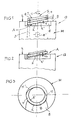
- a screw spindle gear G indicated schematically in FIGS. 1 and 2 has as Main components include a screw spindle S and a spindle nut M.
- a relative rotation (arrow 1) between these components is either the Spindle nut M can be moved in the axial direction on the screw spindle S, or vice versa the screw spindle S is adjustable relative to the spindle nut M.
- the relative rotational movement (arrow 1) is caused by rotating the Screw spindle S is generated, and the spindle nut M moves along the screw spindle S depending on the direction of rotation.
- the screw spindle S has an external thread 2 matching an internal thread 3 of the spindle nut M.
- rolling elements can be used between these two components. be provided, which along at least one thread-like guideway the screw spindle S and / or in the spindle nut M.
- the screw spindle drive G has a built-in thread wear indicator mechanism M provided with the thread wear or to read measure is.
- one of the thread pitches is on the spindle nut M. following visible edge K visible from the outside as belonging to the spindle nut M. Display element and an edge K 'assigned locally to the visible edge K, which also the thread pitch follows, provided as a display element on the screw spindle S.
- the axial distance in Fig. 1 (between the visible edge K and the edge K ') is a visible one or measurable display for thread wear.
- Fig. 1 is in the screw transmission G there is no significant thread wear (axial distance x accordingly e.g. the axial thread play).
- the visible edge K coincides approximately the edge K 'or lies opposite it with the axial distance x.
- the distance is in Radial view of the axis of the screw spindle S to see or measure.
- Fig. 2 has occurred thread wear. Assuming that a load condition is present in the screw spindle gearbox G with a specific load direction L, down in the drawing, is due to the thread wear that has occurred 2 the visible edge K with a significantly larger axial distance x1 before the edge K '.
- the axial thread play has increased visibly and measurably.
- the external thread 2 of the screw spindle S is a trapezoidal thread (e.g. single-start Trapezoidal thread, although multi-start threads are also possible) with one relatively wide aisle crest 4, which is delimited by striking edges 6, 7 and one Relatively wide, flat gangway 5, which also in the transitions into the gangways shows striking edges.
- a trapezoidal thread e.g. single-start Trapezoidal thread, although multi-start threads are also possible
- one relatively wide aisle crest 4 which is delimited by striking edges 6, 7 and one Relatively wide, flat gangway 5, which also in the transitions into the gangways shows striking edges.
- the visible edge K of the spindle nut M locally assigned edge K 'is, for example, the lower edge 6 of the crest 4 used.
- the visible edge K of the spindle nut M is in a recess formed on an end face 9 8 exposed, i.e. that at least one peripheral portion (Fig. 3) of the transition from the bottom of the passage 4 'of the internal thread 3 into a load-bearing one Aisle edge 10 is visible.
- the visible edge K does not necessarily need exactly that Transition from the base of the gear 4 'to the gear flank 10, but could also be due to greater ablation within the root 4 '.
- Illustrated in Fig. 3 the reference number 10 the thread start from the internal thread comb 5 'in the Gang base 4 'on the front side 9 of the spindle nut M, while the reference number 11' Intersection line between the end face 9 and the internal thread crest 5 suggests.
- the spindle nut could M be extended with an axial extension on which the visible edge K or at least a pointer tip in local assignment (with the thread clearance) for example to the Edge K 'of the external thread 2 of the screw spindle S is arranged around the one Thread wear under load L relative axial adjustment of the visible edge Read K or the at least one point of the visible edge K relative to the edge K ' allow.
- lauter tun chopping machine T serves a motor M1 as a rotary drive for loosening elements, not shown, with which deposited Grains can be loosened by a slow rotation.
- a second Drive motor M2 is used to adjust the height of the loosening elements with a Screw spindle gear G, the screw spindle S by the drive motor M2 in one or the other direction of rotation is driven around which the loosening elements carrying spindle nut M up or down.
- the screw spindle gear G for example designed according to FIGS. 1 to 3, is integrated with the Thread wear indicator mechanism A between the spindle nut M and the Screw spindle S equipped.
- the screw spindle transmission G is in a tubular housing 12 in an oil bath accommodated.
- the spindle nut M is provided with springs 15 which are in guide grooves 16 are guided axially, so that the spindle nut M is rotatably and axially adjustable is supported.
- An inspection opening 13 in the housing 12 is by a removable Lid 14 closed, preferably a sight glass, around the thread wear indicator mechanism M optically and without dismantling the screw spindle gear G inspect.
- an oil drain device 15 is provided, expediently an oil drain valve around the lower portion of the housing 12 around the thread wear indicator mechanism M to be able to expose. After removing the cover 14 leaves Measure thread wear that occurs, for example using a gap gauge which is inserted into the space between the visible edge K and the edge K ', or check and evaluate with the naked eye or an endoscope.
- the recess 8 is expedient milled in the end face 9 of the spindle nut M, from the outer circumference the spindle nut M up to the diameter of the base 4 'in FIG. 3.
- This processing makes the visible edge exactly following the thread pitch exposed without noticeably weakening the spindle nut M or the wearing properties to influence.
- To form an even more precise visible edge K could also an axial machining of the visible edge in the direction of the thread pitch K can be made.
- FIG. 1 there is a recess 8 ', for example in the form of a radial bore shown, the top or bottom inner circumference point of the visible edge K or at least forms a point of such a visible edge.
- a mark or a projection in the manner of a pointer.
Landscapes
- Chemical & Material Sciences (AREA)
- Organic Chemistry (AREA)
- Engineering & Computer Science (AREA)
- General Health & Medical Sciences (AREA)
- Food Science & Technology (AREA)
- Biochemistry (AREA)
- Bioinformatics & Cheminformatics (AREA)
- General Engineering & Computer Science (AREA)
- Health & Medical Sciences (AREA)
- Genetics & Genomics (AREA)
- Life Sciences & Earth Sciences (AREA)
- Wood Science & Technology (AREA)
- Zoology (AREA)
- Physics & Mathematics (AREA)
- General Physics & Mathematics (AREA)
- Transmission Devices (AREA)
- Slot Machines And Peripheral Devices (AREA)
- Gears, Cams (AREA)
Abstract
Description
- Fig. 1
- eine Seitenansicht eines Teils eines Schraubspindelgetriebes, in einem Lastzustand und ohne Gewindeverschleiß,
- Fig. 2
- das Schraubspindelgetriebe von Fig. 1 bei Gewindeverschleiß,
- Fig. 3
- eine Stirnansicht der Spindelmutter des Schraubspindelgetriebes der Fig. 1 und 2, ohne die Schraubspindel, und
- Fig. 4
- schematisch einen Teil einer Läuterbottich-Aufhackmaschine, teilweise im Axialschnitt, mit einem Schraubspindelgetriebe der in den Fig. 1 und 3 angedeuteten Art, wobei in der linken Hälfte der Schnittdarstellung die Spindelmutter eine tiefe Position, in der rechten Hälfte hingegen eine angehobene Position einnimmt.
Claims (10)
- Schraubspindelgetriebe (G), insbesondere für eine Läuterbottich-Aufhackmaschine (T), mit einer Spindelmutter (M), die durch eine relative Drehbewegung (1) zwischen der Schraubspindel (S) und der Spindelmutter (M) entlang des Außengewindes (2) der Schraubspindel (S) verstellbar ist, gekennzeichnet durch einen in das Schraubspindelgetriebe (G) zwischen der Spindelmutter (M) und der Schraubspindel (S) baulich integrierten Gewindeverschleiß-Anzeigemechanismus (A).
- Schraubspindelgetriebe nach Anspruch 1, dadurch gekennzeichnet, dass der Gewindeverschleiß-Anzeigemechanismus (A) zusammen mit der Spindelmutter (M) auf der Gewindespindel (S) verstellbar ist, vorzugsweise in Axialrichtung und in der Richtung der relativen Drehbewegung.
- Schraubspindelgetriebe nach Anspruch 1, dadurch gekennzeichnet, dass an der Spindelmutter (M) und der Schraubspindel (S) jeweils wenigstens ein von außerhalb der Spindelmutter (M) sichtbar und fest angebrachtes Anzeigeelement vorgesehen ist, und dass die Anzeigeelemente in einem Lastzustand mit vorbestimmter axialer Lastrichtung (L) des Schraubspindelgetriebes (G) in Axialrichtung einander örtlich derart zugeordnet sind, z.B. mit dem axialen Gewindespiel, dass sie sichtbar, vorzugsweise zumindest messbar, gewindeverschleißabhängig relativ zueinander verstellbar sind.
- Schraubspindelgetriebe nach Anspruch 3, dadurch gekennzeichnet, dass das Anzeigeelement der Spindelmutter (M) eine in ihrem Verlauf der Gewindesteigung entsprechende Sichtkante (K) aufweist, und dass das Anzeigeelement der Schraubspindel eine im Außengewinde sichtbare, markante, der Gewindesteigung folgende Kante (K') ist, vorzugsweise an einem Kamm (4) und/oder Grund (5) wenigstens eines Gewindeganges.
- Schraubspindelgetriebe nach Anspruch 4, dadurch gekennzeichnet, dass in wenigstens einer Stirnseite (9) der Spindelmutter (M) in einem Umfangssegment eine vom Außenumfang bis an den Gewindegrund (4') des Innengewindes (3) reichende Ausnehmung (8) geformt ist, innerhalb derer der freigelegte Übergang von der Gangflanke (10) in den Gewindegrund (4') die Sichtkante (K) definiert.
- Schraubspindelgetriebe nach Anspruch 5, dadurch gekennzeichnet, dass das Gewinde ein Trapezgewinde mit einem Gewindegrund (5, 4') definierter Weite, einem kantigen Übergang vom Gewindegrund (5, 4') in die Gangflanke (10), einem zumindest weitgehend ebenen Kamm (4, 5') definierter Weite, und den Kamm (4) begrenzenden Kanten (6, 7) ist, von denen eine Kante (6) als die örtlich, z.B. mit dem Gewindespiel bei verschließfreien Gewinden, der Sichtkante (K) zugeordnete Kante (K') ausgewählt ist.
- Läuterbottich-Aufhackmaschine (M) mit einem Schraubspindelgetriebe (G), mit dem zwischen einer Spindelmutter (M) und einer ein Außengewinde aufweisenden Schraubspindel (S) durch Relatiwerdrehung (1) axiale Lastverstellbewegungen durchführbar sind, dadurch gekennzeichnet, dass in das Schraubspindelgetriebe (G) ein ohne Demontage des Schraubspindelgetriebes (G) zumindest optisch inspizierbarer, selbsttätiger Gewindeverschleiß-Anzeigemechanismus (A) baulich eingegliedert ist.
- Läuterbottich-Aufhackmaschine nach Anspruch 7, dadurch gekennzeichnet, dass der Gewindeverschleiß-Anzeigemechanismus (M) eine vom Innengewinde (3) der Spindelmutter (M) zur Ansicht von außen freigelegte, der Gewindesteigung folgende Sichtkante (K) aufweist, die dem Außengewinde oder einer markanten Kante (K') des Außengewindes der Schraubspindel (S) örtlich zugeordnet ist, und dass in einem Gehäuse (12) des Schraubspindelgetriebes (G) eine auf den Gewindeverschleiß-Anzeigemechanismus (M) ausgerichtete Inspektionsöffnung (13) vorgesehen ist.
- Läuterbottich-Aufhackmaschine nach Anspruch 8, dadurch gekennzeichnet, dass die Inspektionsöffnung (13) durch einen abnehmbaren Deckel (14), vorzugsweise ein Schauglas, verschlossen ist, und dass das Gehäuse (12) eine Ölablassvorrichtung (15) aufweist.
- Läuterbottich-Aufhackmaschine nach wenigstens einem der Ansprüche 7 bis 9, dadurch gekennzeichnet, dass die Spindelmutter (M) und die Schraubspindel (S) Trapezgewinde aufweisen, und dass die Dichtkante (K) zumindest ein Umfangsabschnitt des Gewindegrundes (4') des Innengewindes (3) ist, dessen axiale Relativposition gegenüber einer markanten Kante (K') des Außengewindes der Schraubspindel (S) in einem Lastzustand des Schraubspindelgetriebes (G) den Gewindeverschleiß (x1) repräsentiert.
Applications Claiming Priority (2)
| Application Number | Priority Date | Filing Date | Title |
|---|---|---|---|
| DE20108680U DE20108680U1 (de) | 2001-05-23 | 2001-05-23 | Schraubspindelgetriebe und Läuterbottich-Aufhackmaschine |
| DE20108680U | 2001-05-23 |
Publications (2)
| Publication Number | Publication Date |
|---|---|
| EP1260786A2 true EP1260786A2 (de) | 2002-11-27 |
| EP1260786A3 EP1260786A3 (de) | 2007-01-24 |
Family
ID=7957260
Family Applications (1)
| Application Number | Title | Priority Date | Filing Date |
|---|---|---|---|
| EP02010328A Withdrawn EP1260786A3 (de) | 2001-05-23 | 2002-05-07 | Schraubspindelgetriebe und Läuterbottich-Aufhackmaschine |
Country Status (2)
| Country | Link |
|---|---|
| EP (1) | EP1260786A3 (de) |
| DE (1) | DE20108680U1 (de) |
Family Cites Families (4)
| Publication number | Priority date | Publication date | Assignee | Title |
|---|---|---|---|---|
| US2066073A (en) * | 1936-02-25 | 1936-12-29 | American Tool Works Co | Safety device for elevating or translating mechanism |
| US2187390A (en) * | 1938-03-30 | 1940-01-16 | Reliance Elevator Mfg Company | Safety and indicating mechanism for elevators |
| GB896914A (en) * | 1958-03-25 | 1962-05-23 | Zd Y V I Plzen | A device for indicating the allowable wear of a nut |
| JPS5640701A (en) * | 1979-09-12 | 1981-04-17 | Sumitomo Heavy Ind Ltd | Measuring method for extent of wear of driving screw |
-
2001
- 2001-05-23 DE DE20108680U patent/DE20108680U1/de not_active Expired - Lifetime
-
2002
- 2002-05-07 EP EP02010328A patent/EP1260786A3/de not_active Withdrawn
Also Published As
| Publication number | Publication date |
|---|---|
| DE20108680U1 (de) | 2001-08-16 |
| EP1260786A3 (de) | 2007-01-24 |
Similar Documents
| Publication | Publication Date | Title |
|---|---|---|
| DE69424879T2 (de) | Lagerverschleissanzeiger | |
| DE2457334A1 (de) | Verfahren und anzeigegeraet zur anzeige der profilabnutzung eines fahrzeugreifens | |
| DE3123480A1 (de) | Aufloesewalzeneinheit fuer offenend-spinnaggregate | |
| DE102010015722A1 (de) | Lageranordnung, insbesondere für ein Spindellager | |
| DE202011100601U1 (de) | Holz- oder Kunststoffschraube | |
| DE102007018054B4 (de) | Scheibenfilter und Sektoren für Scheibenfilter | |
| DE2755069A1 (de) | Vorrichtung zur ueberwachung der axialen auslenkung von turbomaschinenkupplungen | |
| DE102008037202B4 (de) | Interferenzschraube | |
| DE102008015617A1 (de) | Kollerverstellvorrichtung | |
| DE102004037414A1 (de) | Zentrifugalabscheider | |
| DE102009038159A1 (de) | Spinnereimaschine mit Ölversorgungseinrichtung für wenigstens eine Spinnspindel | |
| DE20108680U1 (de) | Schraubspindelgetriebe und Läuterbottich-Aufhackmaschine | |
| DE3600721C2 (de) | ||
| EP0099449A2 (de) | Vorrichtung zur Abdichtung eines Zahnkranzes | |
| EP2243632A2 (de) | Rotationsbürste mit unterschiedlichem Borstenbesatz | |
| DE20306899U1 (de) | Wälzlager mit wenigstens einem segmentierten Lagerring | |
| DE19518194A1 (de) | Schneckengetriebe | |
| DE4410580B4 (de) | Ultraschall-Prüfungsmaschine für längliche Prüfstücke mit einem Rotor und einem Stator | |
| DE4447297C2 (de) | Meßeinrichtung für Ventilsitze kleineren Durchmessers | |
| DE10317488A1 (de) | Technoskop | |
| DE29821754U1 (de) | Meßvorrichtung zur spektralphotometrischen Messung von Flüssigkeiten im UV/VIS- oder VIS/NIR-Bereich | |
| DE2623590B2 (de) | Dichtungsanordnung für umlaufende oder gleitbewegliche Wellen | |
| DE102020115752A1 (de) | Schneckenfilter mit beidseitig gelagerter Schnecke | |
| DE102009024724A1 (de) | Getriebe für einen Kernumfassungsschrauben-Manipulator | |
| DE102006011940B4 (de) | Rücklaufelement für eine Kugelumlaufspindel |
Legal Events
| Date | Code | Title | Description |
|---|---|---|---|
| PUAI | Public reference made under article 153(3) epc to a published international application that has entered the european phase |
Free format text: ORIGINAL CODE: 0009012 |
|
| AK | Designated contracting states |
Kind code of ref document: A2 Designated state(s): AT BE CH CY DE DK ES FI FR GB GR IE IT LI LU MC NL PT SE TR |
|
| AX | Request for extension of the european patent |
Free format text: AL;LT;LV;MK;RO;SI |
|
| RAP1 | Party data changed (applicant data changed or rights of an application transferred) |
Owner name: KRONES AKTIENGESELLSCHAFT |
|
| PUAL | Search report despatched |
Free format text: ORIGINAL CODE: 0009013 |
|
| AK | Designated contracting states |
Kind code of ref document: A3 Designated state(s): AT BE CH CY DE DK ES FI FR GB GR IE IT LI LU MC NL PT SE TR |
|
| AX | Request for extension of the european patent |
Extension state: AL LT LV MK RO SI |
|
| AKX | Designation fees paid | ||
| STAA | Information on the status of an ep patent application or granted ep patent |
Free format text: STATUS: THE APPLICATION IS DEEMED TO BE WITHDRAWN |
|
| 18D | Application deemed to be withdrawn |
Effective date: 20070725 |
|
| REG | Reference to a national code |
Ref country code: DE Ref legal event code: 8566 |