EP1260487B1 - Blaskopf - Google Patents
Blaskopf Download PDFInfo
- Publication number
- EP1260487B1 EP1260487B1 EP01112558A EP01112558A EP1260487B1 EP 1260487 B1 EP1260487 B1 EP 1260487B1 EP 01112558 A EP01112558 A EP 01112558A EP 01112558 A EP01112558 A EP 01112558A EP 1260487 B1 EP1260487 B1 EP 1260487B1
- Authority
- EP
- European Patent Office
- Prior art keywords
- blow head
- blow
- gob
- set forth
- head
- Prior art date
- Legal status (The legal status is an assumption and is not a legal conclusion. Google has not performed a legal analysis and makes no representation as to the accuracy of the status listed.)
- Expired - Lifetime
Links
- 238000007664 blowing Methods 0.000 claims abstract description 21
- 239000011521 glass Substances 0.000 claims abstract description 19
- 238000004519 manufacturing process Methods 0.000 claims description 4
- 238000000034 method Methods 0.000 description 4
- 239000012530 fluid Substances 0.000 description 3
- 230000015572 biosynthetic process Effects 0.000 description 1
- 230000001419 dependent effect Effects 0.000 description 1
- 238000011161 development Methods 0.000 description 1
- 230000018109 developmental process Effects 0.000 description 1
- 238000007373 indentation Methods 0.000 description 1
- 239000000314 lubricant Substances 0.000 description 1
- 238000007789 sealing Methods 0.000 description 1
- 230000001360 synchronised effect Effects 0.000 description 1
Images
Classifications
-
- C—CHEMISTRY; METALLURGY
- C03—GLASS; MINERAL OR SLAG WOOL
- C03B—MANUFACTURE, SHAPING, OR SUPPLEMENTARY PROCESSES
- C03B9/00—Blowing glass; Production of hollow glass articles
- C03B9/30—Details of blowing glass; Use of materials for the moulds
- C03B9/36—Blow heads; Supplying, ejecting or controlling the air
- C03B9/3618—Means for holding or transferring the blow head
-
- C—CHEMISTRY; METALLURGY
- C03—GLASS; MINERAL OR SLAG WOOL
- C03B—MANUFACTURE, SHAPING, OR SUPPLEMENTARY PROCESSES
- C03B9/00—Blowing glass; Production of hollow glass articles
- C03B9/30—Details of blowing glass; Use of materials for the moulds
- C03B9/36—Blow heads; Supplying, ejecting or controlling the air
- C03B9/3654—Details thereof relating to neck forming
Definitions
- blow heads are used, which are pressed onto a goblet in a mold become. After introducing compressed air, the gob becomes inflated and attaches to the inner walls of the mold, causing the desired hollow glass product is formed, e.g. a bottle or a bottle. After inflation, the compressed air supply shut off and the shell parts of the mold are removed and then the blow head. After removing the jacket parts It may be that the glass product through the on the Blaskopf acting force is slightly deformed, what the one a certain variance in the dimensional accuracy of the produced Shaped body brings and on the other hand increases the committee.
- US-A-3,871,856 describes a die that does not have any on the Glsposten adjacent surface. There is no here Deformation of the product by the die instead. on the other hand if the possibility of forming is not used by the blow head, what it requires is that the product is in a separate top Step must be formed
- the fitting against the gob is part the Blaskopfes transverse to the contact surface or in the blowing direction movably arranged in the blow head.
- the blowhead is here biased by compressed air or a pressurized fluid against the gob, as long as the gob is inflated. After the finished blowing the pressure is removed from the pressure fluid, whereby the moving part is no longer under tension against the gob is present, but only on the wind to be blown Product rests.
- pressurized fluid the blown air is used, with which the hollow glass product is inflated.
- the blowing heads are symmetrical, in particular rotationally symmetrical trained around the blow channel.
- the against the Goblet adjacent moving part of the blow head is then preferably rotationally symmetrical and axially movable about the Blaskanal arranged around.
- the glass post facing bottom or front side of the movable part forms the contact surface against the glass product and forms the blowing process Top of the mouth region of the glass product.
- the compressed air supply facing end faces of axially movable part as a rotationally symmetric annular surfaces trained, which acts on the blowing pressure and thus against to be preloaded the gob.
- Such a training the Blaskopfes is relatively inexpensive, namely by turning produce and leads to a uniform force application.
- the cylindrical walls between the stationary part of the blow head and the movable part are preferably substantially pressure tight against each other, or contain a seal, e.g. O-ring seal, so that when preloading the moving Partly against the gob in the context of the blowing process no compressed air drops on this sliding surface.
- a seal this sliding surfaces can preferably by a sealing Lubricants and / or seals are supported.
- the pressurization area the axially movable part of the blow head can either be pressurized directly from the blow duct or over separate compressed air supply ducts that run diagonally from the Blaskanal from down toward the annular pressure surface extend the axially movable part of the blow head. In this way, a uniform force application achieved on the moving part of the blow head, which the occurrence tilting moments or tilting in the sliding surface prevent.
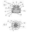
- the blowing head 10 will be described below with reference to FIGS. 1 and 2.
- the blowing head 10 is rotationally symmetrical about the Blaskanal 12 constructed and contains an outer stationary Part 14, which has an inner axially movable along the blowing channel 12 Part 16 encloses cylindrical.
- the movement of the movable part 16 forward in the direction of the gob, to arrange in the drawing at the bottom of Blaskopfes would be limited by an annular stop plate 18, by screws 20 with the stationary part 14 of the Blaskopfes 10 is connected.
- At the blowing air supply facing Front side are two annular surfaces 22, 24 formed, the associated shoulders 26, 28 of the stationary part 14th the Blaskopfes 10 are spaced so that in the resulting Rooms compressed air are supplied from the blown air source can.
- the blown air is the staircase down offset outer annular surface 24 via eight compressed air lines 30, which is offset at 45 ° to the blow port 12th around (Fig. 2) are arranged.
- a indentation 32 which is the upper part of Blow mold for the formation of the confluence of a hollow glass product, e.g. a bottle or a bottle.
- a gob i.e. an operating temperature, e.g. 1000 ° C, located Glass mass of defined mass or size becomes a blow mold transferred.
- the blow head is on the in-mold to be inflated gob and placed under pressure.
- the axially movable part 14 is pressed firmly against the gob and simultaneously via the coaxial blower channels 12a of the stationary part 14 and 12b of the movable part 16 of the blow head 10 compressed air injected into the gob, which itself then applied to the walls of the blow mold and its final shape is blown out.
Landscapes
- Engineering & Computer Science (AREA)
- Chemical & Material Sciences (AREA)
- Manufacturing & Machinery (AREA)
- Materials Engineering (AREA)
- Organic Chemistry (AREA)
- Blow-Moulding Or Thermoforming Of Plastics Or The Like (AREA)
- Re-Forming, After-Treatment, Cutting And Transporting Of Glass Products (AREA)
- Containers Having Bodies Formed In One Piece (AREA)
Description
- Fig. 1
- einen Querschnitt durch einen erfindungsgemäßen Blaskopf gemäß der Schnittlinie I-I aus Figur 2 und
- Fig. 2
- eine Aufsicht auf den Blaskopf in Richtung des Pfeils II aus Figur 1.
Claims (10)
- Blaskopf zur Herstellung eines Glasprodukts aus einem Glasposten, mit einem gegen einen Glasposten anliegenden Teil (16), welcher Blaskopf (10) zumindest eine Gasdurchführung (12) zur Einleitung von Gas in den Glasposten aufweist, wobei der an dem Glasposten anliegende Teil (16) des Blaskopfes (10) senkrecht zu einer Anlagefläche (32) des Teils (16) beweglich ist und wenigstens eine an der vom Glasposten abgewandten Seite des Teils (16) liegende Druckfläche (22,24) zur Vorspannung des beweglichen Teils (16) gegen den Glasposten aufweist, wobei der Blaskopf derart ausgebildet ist, dass das eingeleitete Gas auch die Druckfläche beaufschlagt.
- Blaskopf nach Anspruch 1,
der rotationssymmetrisch um einen zentrischen Blaskanal (12) ausgebildet ist, wobei der bewegliche Teil (16) als dem Posten zugewandter axial beweglicher Ringkolben ausgebildet ist, dessen dem Posten abgewandte Stirnseite (22,24) die Druckfläche bildet. - Blaskopf nach einem der vorhergehenden Ansprüche,
bei dem zwischen einem stationären Teil (14) des Blaskopfes und dem beweglichen Teil (16) des Blaskopfes ein über Druckkanäle druckbeaufschlagbarer Raum ausgebildet ist. - Blaskopf nach einem der vorhergehenden Ansprüche,
der axial einen Blaskanal (12) umschließt, und zwischen einem stationären Teil (14) und dem beweglichen Teil (16) des Blaskopfes wenigstens eine, vorzugsweise senkrecht zur Achse liegende Schulter (22,24) ausgebildet ist, die sich symmetrisch um die Achse erstreckt(en). - Blaskopf nach Anspruch 4,
bei dem der stationäre (14) und der bewegliche Teil (16) einander zugewandte in axialer Richtung verlaufende Gleitflächen aufweisen, die im wesentlichen druckdicht abschließen. - Blaskopf nach Anspruch 4 oder 5, bei dem die Schulter als koaxial den Blaskanal (12) umgebende Ringfläche (22,24) ausgebildet ist.
- Blaskopf nach Anspruch 6,
bei dem symmetrisch um den Blaskanal (12) Druckkanäle (30) ausgebildet sind, die sich von dem Blaskanal (12) schräg radial in Blasrichtung nach außen erstrecken und in einem Ringraum zwischen einer Schulter (26,28) des stationären (14) und einer Schulter (22,24) des beweglichen Blaskopfteils (16) einmünden. - Blaskopf nach einem der vorhergehenden Ansprüche,
bei dem zwischen dem stationären (14) und beweglichen Teil (16) des Blaskopfes wenigstens eine Anschlagsfläche (18) vorgesehen ist, die die Bewegung des beweglichen Teils (16) in Richtung auf den Posten begrenzt. - Blaskopf nach Anspruch 8 und einem der Ansprüche 4 bis 7, bei dem die Anschlagsfläche (18) als lösbar (20) mit dem stationären Teil (14) des Blaskopfes verbindbarer Platte oder Ring ausgebildet ist, die/der den beweglichen Teil (16) radial nach innen übergreift.
- Blaskopf nach einem der vorhergehenden Ansprüche,
der ein Verbindungsteil (34) zum Einsetzen in eine Herstellungsmaschine für Hohlglas aufweist.
Priority Applications (4)
| Application Number | Priority Date | Filing Date | Title |
|---|---|---|---|
| AT01112558T ATE303351T1 (de) | 2001-05-23 | 2001-05-23 | Blaskopf |
| EP01112558A EP1260487B1 (de) | 2001-05-23 | 2001-05-23 | Blaskopf |
| ES01112558T ES2245959T3 (es) | 2001-05-23 | 2001-05-23 | Cabezal de soplado. |
| DE50107280T DE50107280D1 (de) | 2001-05-23 | 2001-05-23 | Blaskopf |
Applications Claiming Priority (1)
| Application Number | Priority Date | Filing Date | Title |
|---|---|---|---|
| EP01112558A EP1260487B1 (de) | 2001-05-23 | 2001-05-23 | Blaskopf |
Publications (2)
| Publication Number | Publication Date |
|---|---|
| EP1260487A1 EP1260487A1 (de) | 2002-11-27 |
| EP1260487B1 true EP1260487B1 (de) | 2005-08-31 |
Family
ID=8177520
Family Applications (1)
| Application Number | Title | Priority Date | Filing Date |
|---|---|---|---|
| EP01112558A Expired - Lifetime EP1260487B1 (de) | 2001-05-23 | 2001-05-23 | Blaskopf |
Country Status (4)
| Country | Link |
|---|---|
| EP (1) | EP1260487B1 (de) |
| AT (1) | ATE303351T1 (de) |
| DE (1) | DE50107280D1 (de) |
| ES (1) | ES2245959T3 (de) |
Cited By (1)
| Publication number | Priority date | Publication date | Assignee | Title |
|---|---|---|---|---|
| CN106830662A (zh) * | 2016-12-25 | 2017-06-13 | 重庆天和玻璃有限公司 | 玻璃瓶二次成型补气装置 |
Family Cites Families (2)
| Publication number | Priority date | Publication date | Assignee | Title |
|---|---|---|---|---|
| US3871856A (en) * | 1973-10-11 | 1975-03-18 | Emhart | Self-aligning baffle and blowhead assembly |
| DE19713281A1 (de) * | 1997-03-29 | 1998-10-01 | Oberland Glas | Blaskopf |
-
2001
- 2001-05-23 EP EP01112558A patent/EP1260487B1/de not_active Expired - Lifetime
- 2001-05-23 ES ES01112558T patent/ES2245959T3/es not_active Expired - Lifetime
- 2001-05-23 AT AT01112558T patent/ATE303351T1/de not_active IP Right Cessation
- 2001-05-23 DE DE50107280T patent/DE50107280D1/de not_active Expired - Lifetime
Cited By (2)
| Publication number | Priority date | Publication date | Assignee | Title |
|---|---|---|---|---|
| CN106830662A (zh) * | 2016-12-25 | 2017-06-13 | 重庆天和玻璃有限公司 | 玻璃瓶二次成型补气装置 |
| CN106830662B (zh) * | 2016-12-25 | 2019-06-07 | 重庆重玻节能玻璃有限公司 | 玻璃瓶二次成型补气装置 |
Also Published As
| Publication number | Publication date |
|---|---|
| ATE303351T1 (de) | 2005-09-15 |
| DE50107280D1 (de) | 2005-10-06 |
| EP1260487A1 (de) | 2002-11-27 |
| ES2245959T3 (es) | 2006-02-01 |
Similar Documents
| Publication | Publication Date | Title |
|---|---|---|
| DE102007032434B4 (de) | Blasvorrichtung zum Expandieren von Behältnissen | |
| DE1218138B (de) | Verfahren und Vorrichtung zum Herstellen von Hohlkoerpern aus thermoplastischem Kunststoff | |
| DE4117010A1 (de) | Maschine fuer das blasformen von verpackung aus bi-orientiertem pet sowie angewandtes blasformverfahren | |
| DE19510195C2 (de) | Verfahren zum Herstellen blankgepreßter Glaskörper für optische Ausrüstungen und Vorrichtung zur Durchführung des Verfahrens | |
| EP1129039B1 (de) | Verfahren und vorrichtung zum pressen eines külbels | |
| DE19833006B4 (de) | Verfahren und Vorrichtung zur Herstellung rohrförmiger gebogener Hohlkörper durch Innenhochdruckumformen | |
| DE19851048A1 (de) | IS-Maschine | |
| EP1261472B1 (de) | Vorrichtung und verfahren zur herstellung von hohlkörpern aus kunststoff | |
| DE19851133A1 (de) | IS-Maschine | |
| EP1260487A1 (de) | Blaskopf | |
| DE102014014144A1 (de) | Verfahren und Vorrichtung zur Herstellung einer optimierten Halskontur an Preformen | |
| DE10040675C1 (de) | Verfahren und Vorrichtung zum Ausformen des Bodens eines Glasgefäßes | |
| EP1954637B1 (de) | Verfahren zum herstellen von glasgegenständen, insbesondere verschlusskörpern aus glas, sowie vorrichtung, anlage und deren verwendung | |
| EP1568663B1 (de) | Vorformstation einer Press-Blas-Glasformmaschine | |
| DE9109287U1 (de) | Formwerkzeug zur Herstellung von Kunststoffbechern | |
| DE10320345A1 (de) | Anlage zur Herstellung von Glasstopfen zum Verschluss von Flaschen | |
| DE19851098A1 (de) | Is-Maschine | |
| DE19851071A1 (de) | IS-Maschine | |
| DE3025333A1 (de) | Vorrichtung zum formen von kuelbeln zur herstellung von enghalsigen glaswaren nach dem press-blas-verfahren | |
| DE19851081A1 (de) | Is-Maschine | |
| EP3426460B1 (de) | Leckagefreie verbindung für blasformmaschinen | |
| DE19851132A1 (de) | IS-Maschine | |
| EP1480810B1 (de) | Halterung für die blasdorne einer blasformeinrichtung | |
| DE2850869C3 (de) | Vorformboden einer zweiteiligen Vorform zum Herstellen von Gläsern, Flaschen oder dergl. Behältnissen aus Glas | |
| DE1471904B2 (de) | Vorrichtung zum Formen von Glas |
Legal Events
| Date | Code | Title | Description |
|---|---|---|---|
| PUAI | Public reference made under article 153(3) epc to a published international application that has entered the european phase |
Free format text: ORIGINAL CODE: 0009012 |
|
| AK | Designated contracting states |
Kind code of ref document: A1 Designated state(s): AT BE CH CY DE DK ES FI FR GB GR IE IT LI LU MC NL PT SE TR |
|
| AX | Request for extension of the european patent |
Free format text: AL;LT;LV;MK;RO;SI |
|
| 17P | Request for examination filed |
Effective date: 20030513 |
|
| AKX | Designation fees paid |
Designated state(s): AT BE DE ES FR IT |
|
| 17Q | First examination report despatched |
Effective date: 20041122 |
|
| GRAP | Despatch of communication of intention to grant a patent |
Free format text: ORIGINAL CODE: EPIDOSNIGR1 |
|
| GRAS | Grant fee paid |
Free format text: ORIGINAL CODE: EPIDOSNIGR3 |
|
| RAP1 | Party data changed (applicant data changed or rights of an application transferred) |
Owner name: HEINZ-GLAS GMBH |
|
| GRAA | (expected) grant |
Free format text: ORIGINAL CODE: 0009210 |
|
| AK | Designated contracting states |
Kind code of ref document: B1 Designated state(s): AT BE DE ES FR IT |
|
| REF | Corresponds to: |
Ref document number: 50107280 Country of ref document: DE Date of ref document: 20051006 Kind code of ref document: P |
|
| REG | Reference to a national code |
Ref country code: ES Ref legal event code: FG2A Ref document number: 2245959 Country of ref document: ES Kind code of ref document: T3 |
|
| ET | Fr: translation filed | ||
| PLBE | No opposition filed within time limit |
Free format text: ORIGINAL CODE: 0009261 |
|
| STAA | Information on the status of an ep patent application or granted ep patent |
Free format text: STATUS: NO OPPOSITION FILED WITHIN TIME LIMIT |
|
| 26N | No opposition filed |
Effective date: 20060601 |
|
| PGFP | Annual fee paid to national office [announced via postgrant information from national office to epo] |
Ref country code: ES Payment date: 20080529 Year of fee payment: 8 |
|
| PGFP | Annual fee paid to national office [announced via postgrant information from national office to epo] |
Ref country code: AT Payment date: 20080515 Year of fee payment: 8 |
|
| PGFP | Annual fee paid to national office [announced via postgrant information from national office to epo] |
Ref country code: BE Payment date: 20080620 Year of fee payment: 8 |
|
| BERE | Be: lapsed |
Owner name: *HEINZ-GLAS G.M.B.H. Effective date: 20090531 |
|
| PG25 | Lapsed in a contracting state [announced via postgrant information from national office to epo] |
Ref country code: AT Free format text: LAPSE BECAUSE OF NON-PAYMENT OF DUE FEES Effective date: 20090523 |
|
| PG25 | Lapsed in a contracting state [announced via postgrant information from national office to epo] |
Ref country code: BE Free format text: LAPSE BECAUSE OF NON-PAYMENT OF DUE FEES Effective date: 20090531 |
|
| REG | Reference to a national code |
Ref country code: ES Ref legal event code: FD2A Effective date: 20090525 |
|
| PG25 | Lapsed in a contracting state [announced via postgrant information from national office to epo] |
Ref country code: ES Free format text: LAPSE BECAUSE OF NON-PAYMENT OF DUE FEES Effective date: 20090525 |
|
| REG | Reference to a national code |
Ref country code: DE Ref legal event code: R082 Ref document number: 50107280 Country of ref document: DE Representative=s name: GRAF GLUECK KRITZENBERGER, DE |
|
| REG | Reference to a national code |
Ref country code: DE Ref legal event code: R082 Ref document number: 50107280 Country of ref document: DE Representative=s name: GRAF GLUECK KRITZENBERGER, DE |
|
| REG | Reference to a national code |
Ref country code: DE Ref legal event code: R082 Ref document number: 50107280 Country of ref document: DE Representative=s name: GRAF GLUECK KRITZENBERGER, DE Effective date: 20130129 Ref country code: DE Ref legal event code: R082 Ref document number: 50107280 Country of ref document: DE Representative=s name: GRAF GLUECK KRITZENBERGER, DE Effective date: 20131125 Ref country code: DE Ref legal event code: R081 Ref document number: 50107280 Country of ref document: DE Owner name: HEINZ-GLAS GMBH & CO. KGAA, DE Free format text: FORMER OWNER: HEINZ GLAS GMBH, 96355 TETTAU, DE Effective date: 20131125 Ref country code: DE Ref legal event code: R082 Ref document number: 50107280 Country of ref document: DE Representative=s name: GLUECK - KRITZENBERGER PATENTANWAELTE PARTGMBB, DE Effective date: 20130129 Ref country code: DE Ref legal event code: R082 Ref document number: 50107280 Country of ref document: DE Representative=s name: GLUECK - KRITZENBERGER PATENTANWAELTE PARTGMBB, DE Effective date: 20131125 |
|
| REG | Reference to a national code |
Ref country code: FR Ref legal event code: PLFP Year of fee payment: 15 |
|
| REG | Reference to a national code |
Ref country code: FR Ref legal event code: PLFP Year of fee payment: 16 |
|
| REG | Reference to a national code |
Ref country code: DE Ref legal event code: R082 Ref document number: 50107280 Country of ref document: DE Representative=s name: GLUECK - KRITZENBERGER PATENTANWAELTE PARTGMBB, DE Ref country code: DE Ref legal event code: R081 Ref document number: 50107280 Country of ref document: DE Owner name: HEINZ-GLAS GMBH & CO. KGAA, DE Free format text: FORMER OWNER: HEINZ-GLAS GMBH & CO. KGAA, 98739 PIESAU, DE |
|
| REG | Reference to a national code |
Ref country code: FR Ref legal event code: PLFP Year of fee payment: 17 |
|
| REG | Reference to a national code |
Ref country code: FR Ref legal event code: CA Effective date: 20170612 Ref country code: FR Ref legal event code: CD Owner name: HEINZ GLAS GMBH & CO. KGAA, DE Effective date: 20170612 |
|
| REG | Reference to a national code |
Ref country code: FR Ref legal event code: PLFP Year of fee payment: 18 |
|
| PGFP | Annual fee paid to national office [announced via postgrant information from national office to epo] |
Ref country code: IT Payment date: 20190527 Year of fee payment: 19 Ref country code: DE Payment date: 20190529 Year of fee payment: 19 |
|
| PGFP | Annual fee paid to national office [announced via postgrant information from national office to epo] |
Ref country code: FR Payment date: 20190522 Year of fee payment: 19 |
|
| REG | Reference to a national code |
Ref country code: DE Ref legal event code: R119 Ref document number: 50107280 Country of ref document: DE |
|
| PG25 | Lapsed in a contracting state [announced via postgrant information from national office to epo] |
Ref country code: FR Free format text: LAPSE BECAUSE OF NON-PAYMENT OF DUE FEES Effective date: 20200531 |
|
| PG25 | Lapsed in a contracting state [announced via postgrant information from national office to epo] |
Ref country code: DE Free format text: LAPSE BECAUSE OF NON-PAYMENT OF DUE FEES Effective date: 20201201 |
|
| PG25 | Lapsed in a contracting state [announced via postgrant information from national office to epo] |
Ref country code: IT Free format text: LAPSE BECAUSE OF NON-PAYMENT OF DUE FEES Effective date: 20200523 |