EP1260310B1 - Machine tool for working an elongated workpiece - Google Patents
Machine tool for working an elongated workpiece Download PDFInfo
- Publication number
- EP1260310B1 EP1260310B1 EP02010776A EP02010776A EP1260310B1 EP 1260310 B1 EP1260310 B1 EP 1260310B1 EP 02010776 A EP02010776 A EP 02010776A EP 02010776 A EP02010776 A EP 02010776A EP 1260310 B1 EP1260310 B1 EP 1260310B1
- Authority
- EP
- European Patent Office
- Prior art keywords
- holder
- workpiece
- spindle
- machine tool
- axis
- Prior art date
- Legal status (The legal status is an assumption and is not a legal conclusion. Google has not performed a legal analysis and makes no representation as to the accuracy of the status listed.)
- Expired - Lifetime
Links
Images


Classifications
-
- B—PERFORMING OPERATIONS; TRANSPORTING
- B23—MACHINE TOOLS; METAL-WORKING NOT OTHERWISE PROVIDED FOR
- B23Q—DETAILS, COMPONENTS, OR ACCESSORIES FOR MACHINE TOOLS, e.g. ARRANGEMENTS FOR COPYING OR CONTROLLING; MACHINE TOOLS IN GENERAL CHARACTERISED BY THE CONSTRUCTION OF PARTICULAR DETAILS OR COMPONENTS; COMBINATIONS OR ASSOCIATIONS OF METAL-WORKING MACHINES, NOT DIRECTED TO A PARTICULAR RESULT
- B23Q1/00—Members which are comprised in the general build-up of a form of machine, particularly relatively large fixed members
- B23Q1/72—Auxiliary arrangements; Interconnections between auxiliary tables and movable machine elements
- B23Q1/76—Steadies; Rests
-
- B—PERFORMING OPERATIONS; TRANSPORTING
- B23—MACHINE TOOLS; METAL-WORKING NOT OTHERWISE PROVIDED FOR
- B23Q—DETAILS, COMPONENTS, OR ACCESSORIES FOR MACHINE TOOLS, e.g. ARRANGEMENTS FOR COPYING OR CONTROLLING; MACHINE TOOLS IN GENERAL CHARACTERISED BY THE CONSTRUCTION OF PARTICULAR DETAILS OR COMPONENTS; COMBINATIONS OR ASSOCIATIONS OF METAL-WORKING MACHINES, NOT DIRECTED TO A PARTICULAR RESULT
- B23Q1/00—Members which are comprised in the general build-up of a form of machine, particularly relatively large fixed members
- B23Q1/25—Movable or adjustable work or tool supports
- B23Q1/44—Movable or adjustable work or tool supports using particular mechanisms
- B23Q1/56—Movable or adjustable work or tool supports using particular mechanisms with sliding pairs only, the sliding pairs being the first two elements of the mechanism
- B23Q1/60—Movable or adjustable work or tool supports using particular mechanisms with sliding pairs only, the sliding pairs being the first two elements of the mechanism two sliding pairs only, the sliding pairs being the first two elements of the mechanism
- B23Q1/62—Movable or adjustable work or tool supports using particular mechanisms with sliding pairs only, the sliding pairs being the first two elements of the mechanism two sliding pairs only, the sliding pairs being the first two elements of the mechanism with perpendicular axes, e.g. cross-slides
- B23Q1/621—Movable or adjustable work or tool supports using particular mechanisms with sliding pairs only, the sliding pairs being the first two elements of the mechanism two sliding pairs only, the sliding pairs being the first two elements of the mechanism with perpendicular axes, e.g. cross-slides a single sliding pair followed perpendicularly by a single sliding pair
- B23Q1/623—Movable or adjustable work or tool supports using particular mechanisms with sliding pairs only, the sliding pairs being the first two elements of the mechanism two sliding pairs only, the sliding pairs being the first two elements of the mechanism with perpendicular axes, e.g. cross-slides a single sliding pair followed perpendicularly by a single sliding pair followed perpendicularly by a single rotating pair
-
- B—PERFORMING OPERATIONS; TRANSPORTING
- B23—MACHINE TOOLS; METAL-WORKING NOT OTHERWISE PROVIDED FOR
- B23Q—DETAILS, COMPONENTS, OR ACCESSORIES FOR MACHINE TOOLS, e.g. ARRANGEMENTS FOR COPYING OR CONTROLLING; MACHINE TOOLS IN GENERAL CHARACTERISED BY THE CONSTRUCTION OF PARTICULAR DETAILS OR COMPONENTS; COMBINATIONS OR ASSOCIATIONS OF METAL-WORKING MACHINES, NOT DIRECTED TO A PARTICULAR RESULT
- B23Q7/00—Arrangements for handling work specially combined with or arranged in, or specially adapted for use in connection with, machine tools, e.g. for conveying, loading, positioning, discharging, sorting
- B23Q7/04—Arrangements for handling work specially combined with or arranged in, or specially adapted for use in connection with, machine tools, e.g. for conveying, loading, positioning, discharging, sorting by means of grippers
-
- Y—GENERAL TAGGING OF NEW TECHNOLOGICAL DEVELOPMENTS; GENERAL TAGGING OF CROSS-SECTIONAL TECHNOLOGIES SPANNING OVER SEVERAL SECTIONS OF THE IPC; TECHNICAL SUBJECTS COVERED BY FORMER USPC CROSS-REFERENCE ART COLLECTIONS [XRACs] AND DIGESTS
- Y10—TECHNICAL SUBJECTS COVERED BY FORMER USPC
- Y10T—TECHNICAL SUBJECTS COVERED BY FORMER US CLASSIFICATION
- Y10T29/00—Metal working
- Y10T29/51—Plural diverse manufacturing apparatus including means for metal shaping or assembling
- Y10T29/5104—Type of machine
- Y10T29/5109—Lathe
- Y10T29/5114—Lathe and tool
-
- Y—GENERAL TAGGING OF NEW TECHNOLOGICAL DEVELOPMENTS; GENERAL TAGGING OF CROSS-SECTIONAL TECHNOLOGIES SPANNING OVER SEVERAL SECTIONS OF THE IPC; TECHNICAL SUBJECTS COVERED BY FORMER USPC CROSS-REFERENCE ART COLLECTIONS [XRACs] AND DIGESTS
- Y10—TECHNICAL SUBJECTS COVERED BY FORMER USPC
- Y10T—TECHNICAL SUBJECTS COVERED BY FORMER US CLASSIFICATION
- Y10T408/00—Cutting by use of rotating axially moving tool
- Y10T408/52—Cutting by use of rotating axially moving tool with work advancing or guiding means
- Y10T408/54—Means to intermittently advance work
- Y10T408/545—Rotary, work-supporting means
-
- Y—GENERAL TAGGING OF NEW TECHNOLOGICAL DEVELOPMENTS; GENERAL TAGGING OF CROSS-SECTIONAL TECHNOLOGIES SPANNING OVER SEVERAL SECTIONS OF THE IPC; TECHNICAL SUBJECTS COVERED BY FORMER USPC CROSS-REFERENCE ART COLLECTIONS [XRACs] AND DIGESTS
- Y10—TECHNICAL SUBJECTS COVERED BY FORMER USPC
- Y10T—TECHNICAL SUBJECTS COVERED BY FORMER US CLASSIFICATION
- Y10T408/00—Cutting by use of rotating axially moving tool
- Y10T408/91—Machine frame
- Y10T408/93—Machine frame including pivotally mounted tool-carrier
-
- Y—GENERAL TAGGING OF NEW TECHNOLOGICAL DEVELOPMENTS; GENERAL TAGGING OF CROSS-SECTIONAL TECHNOLOGIES SPANNING OVER SEVERAL SECTIONS OF THE IPC; TECHNICAL SUBJECTS COVERED BY FORMER USPC CROSS-REFERENCE ART COLLECTIONS [XRACs] AND DIGESTS
- Y10—TECHNICAL SUBJECTS COVERED BY FORMER USPC
- Y10T—TECHNICAL SUBJECTS COVERED BY FORMER US CLASSIFICATION
- Y10T409/00—Gear cutting, milling, or planing
- Y10T409/30—Milling
- Y10T409/304536—Milling including means to infeed work to cutter
- Y10T409/30532—Milling including means to infeed work to cutter with means to advance work or product
-
- Y—GENERAL TAGGING OF NEW TECHNOLOGICAL DEVELOPMENTS; GENERAL TAGGING OF CROSS-SECTIONAL TECHNOLOGIES SPANNING OVER SEVERAL SECTIONS OF THE IPC; TECHNICAL SUBJECTS COVERED BY FORMER USPC CROSS-REFERENCE ART COLLECTIONS [XRACs] AND DIGESTS
- Y10—TECHNICAL SUBJECTS COVERED BY FORMER USPC
- Y10T—TECHNICAL SUBJECTS COVERED BY FORMER US CLASSIFICATION
- Y10T409/00—Gear cutting, milling, or planing
- Y10T409/30—Milling
- Y10T409/304536—Milling including means to infeed work to cutter
- Y10T409/305544—Milling including means to infeed work to cutter with work holder
- Y10T409/305656—Milling including means to infeed work to cutter with work holder including means to support work for rotation during operation
-
- Y—GENERAL TAGGING OF NEW TECHNOLOGICAL DEVELOPMENTS; GENERAL TAGGING OF CROSS-SECTIONAL TECHNOLOGIES SPANNING OVER SEVERAL SECTIONS OF THE IPC; TECHNICAL SUBJECTS COVERED BY FORMER USPC CROSS-REFERENCE ART COLLECTIONS [XRACs] AND DIGESTS
- Y10—TECHNICAL SUBJECTS COVERED BY FORMER USPC
- Y10T—TECHNICAL SUBJECTS COVERED BY FORMER US CLASSIFICATION
- Y10T409/00—Gear cutting, milling, or planing
- Y10T409/30—Milling
- Y10T409/306664—Milling including means to infeed rotary cutter toward work
- Y10T409/307672—Angularly adjustable cutter head
Definitions
- the invention relates to a machine tool for machining a rod-shaped workpiece, comprising a traveling column, on which a spindle spindle rotatable about a spindle spindle is mounted, wherein the tool spindle is pivotable about a pivot axis which is perpendicular to both the spindle axis and to a longitudinal axis of the workpiece ,
- the known machine tool is used for processing rod-shaped machine tools, which can also be rotated about its longitudinal axis, for which purpose they are clamped in a first holder, from which they protrude with their end to be machined.
- the machining of this protruding end via a tool spindle, which is arranged on a traveling column, via which the tool spindle is movable in three axes.
- the tool spindle is furthermore pivotable about a pivot axis intersecting the spindle axis.
- a second holder Coaxially with the first holder, a second holder is provided which serves as an abutment for the end of the material rod to be machined.
- a machine tool in which the tool spindle is convertible between a vertical and a horizontal position, so that a horizontal and a vertical machining can be performed with a single spindle.
- the machining of tool bars is not provided in the known machine tool.
- One from the DE 199 19 647 A1 known machine tool is a traveling column machine, on the machine bed, a workpiece clamping device is arranged for a workpiece.
- the workpiece clamping device is pivotable about a horizontal axis, so that a workpiece clamped therein can be machined both longitudinally and at an end face opposite the clamping point by a tool which is received in a tool spindle fastened to the traveling column.
- a kind of robot arm (manipulator) is provided, which is pivotable about a vertical axis and has a gripper. After completion of the processing of the five initially accessible sides of the workpiece, the gripper takes the workpiece out of the workpiece clamping device.
- the robot arm is then pivoted by 90 ° in the horizontal and by 180 ° about its longitudinal axis and the gripper inserted into a tensioning station.
- the tensioning station holds and fixes the gripper and thus the workpiece still recorded in the exact position, so that this now also be machined on its sixth side of the tool.
- a disadvantage of the known machine tool that either only comparatively short workpieces in the workpiece clamping device can be tilted into a vertical position to allow processing of the free end face, or a large pivot space must be provided, which allows the pivoting even longer workpieces.
- Object of the present invention is therefore to improve a machine tool of the type mentioned in such a way that with a spatially compact machine tool and longer workpieces can be edited at its free end face.
- this object is achieved in that the pivot axis is arranged without overlap to the spindle axis.
- the free end face of the workpiece can be processed without the workpiece has to be pivoted. This is particularly advantageous for long workpieces, since this otherwise required pivot space can be omitted.
- the non-overlapping arrangement of the pivot axis and spindle axis allows a structurally simpler and more stable attachment of the spindle on the traveling column, as provided for pivoting the tool spindle pivoting device is not interrupted by the rotary spindle.
- this measure is also advantageous in machine tools in which the pivot axis is not aligned perpendicular to the longitudinal axis of the workpiece, but in another way, in particular parallel thereto.
- the tool spindle is pivotable about a pivot angle of at least 90 °.
- the tool spindle is preferably taken together with a drive for this purpose in a spindle housing, wherein the pivot axis at the height of the front, a tool holder having half, preferably at the height of the front quarter of the spindle housing.
- pivot axis can not be arranged arbitrarily close to the tool, since the space around the tool should remain as free as possible. Only then it is ensured that the tool can reach and work the workpiece in all positions without hindrance by a pivoting device required for the pivotability.
- a pivoting device is in close proximity to an end face of the spindle housing or even flush with this.
- the machine tool has a first and a second holder for receiving the workpiece, wherein the second holder is aligned in a machining position coaxial with the first holder and arranged rotatable or pivotable about an axis perpendicular to a longitudinal axis of the workpiece axis ,
- the workpiece received therein can be moved away from the first holder as far as possible so that the clamping point is also accessible for machining by a tool inserted into the tool spindle.
- this can, for example, previously at one point between the first holder and the second holder have been severed, for example by milling or sawing.
- the workpiece can also be undivided, ie, rotated as a whole, with the second holder or pivoted, if it is previously completely pushed out of the first holder. This can be done, for example, by means of a feed device known per se or else with the aid of a second workpiece, which is introduced into the first holder and thereby pushes the second workpiece out of it.
- the first holder is formed as a rotary table or NC rotary spindle, a six-sided machining of the workpiece is possible, since by turning or pivoting of the second holder and the clamping point of the workpiece is a machining accessible.
- This aspect is particularly important, e.g. in the processing of aluminum profiles, as these are often predominantly frontal at both ends to edit.
- the clamping point of the workpiece which has become free as a result of the turning or pivoting, is approached by the tool spindle and processed with the tool received therein.
- the second holder is rotatable or pivotable by at least 180 °.
- the workpiece held by the second holder can be turned completely, whereby the point where it was previously held in the first holder, is particularly accessible. If necessary, the workpiece can also be turned several times, so that the axial ends of the workpiece can be machined alternately.
- the second holder is rotatably arranged, the coaxial alignment with the first holder after rotation is maintained.
- a pivoting movement of the second holder by 180 °, however, only a parallel, but not a coaxial alignment with the first holder is achieved.
- a pivoting movement is in many cases preferable to a rotational movement, since in this way a workpiece held by the second holder after pivoting will not interfere with a workpiece still in the first holder, e.g. a previously separated part, can collide.
- the second holder is arranged to achieve a pivoting movement eccentric to the vertical axis.
- the vertical axis thus does not intersect the longitudinal axis of the workpiece.
- the second holder is arranged on a support rotatable about the vertical axis.
- On the support at least one further holder is arranged eccentrically to the vertical axis, so that the further holder can be converted by rotating the carrier about the vertical axis in a position coaxial with the first holder.
- the carrier for receiving workpieces available.
- the selected holder By rotating the carrier about the vertical axis, the selected holder is aligned coaxially with the first holder.
- the workpiece may then be e.g. be introduced by displacement in its longitudinal direction in this selected holder and then further processed. It can also be arranged on the carrier similar holders. This is e.g. then useful when another workpiece is to be reintroduced into another holder during the processing of a turned workpiece.
- the other holders are designed differently, in particular as a steady rest, as a sleeve or as a power clamping bracket.
- a holder may be formed, for example, as a quill with a mandrel received therein, which in particular when turning with smaller cutting forces or short workpieces centering with sufficient support of the workpiece is possible.
- Another holder can be designed as a steady rest (butt), with which larger cutting forces can also be supported during long turning.
- the steady rest can support the workpiece, for example, at three circumferential points with fixed jaws or with rollers.
- a power clamping bracket holder in which the workpiece is firmly fixed, the workpiece can be gripped and turned by turning the carrier.
- the use of a power clamping bracket as a holder is expedient.
- the holders are releasably secured to the carrier so that they are interchangeable with holders having other functions. Due to this modular design, the multifunction platform can be adapted to a wide variety of requirements.
- first holder is spatially fixed relative to the machine tool and the second holder is arranged to be movable parallel to the longitudinal axis of the workpiece.
- the second holder which is preferably designed for this purpose as a steady rest, can always be moved in the immediate vicinity of the current processing point. In this way, the workpiece can always optimally short support, so that bending moments occurring do not lead to a deformation of the workpiece.
- the mobility also opens up the possibility of the second holder, possibly together with a carrier on which it is attached with other holders, so far out of the possible processing area, that it does not hinder the machining of a workpiece received in the first holder.
- the second holder allows a fixed fixation of the workpiece in the longitudinal direction, as e.g. is the case with a power clamp, so this can also be used as a feed unit for the workpiece.
- Successively machining portions of the workpiece by advancing the workpiece by a corresponding section length after machining a section and the processing is continued at the next section, wherein the workpiece always also remains held by the first holder.
- the length of the workpiece may even be greater than the width of the machine tool, provided that a possibly present machine housing has suitable openings for the passage of the workpieces.
- the first holder can also be designed as a power clamping bracket. This is expedient if only one machining of the workpiece is provided on its pointing to the tool spindle longitudinal side, so that no rotation of the workpiece about its longitudinal axis is required.
- the first holder is designed as a rotary spindle.
- the first holder is also an NC rotary spindle into consideration, which combines the properties of a rotary spindle with those of a rotary table, ie high rotational speeds and angular positioning.
- Fig. 1 shows in a schematic simplified representation of important components of a machine tool according to the invention, denoted overall by 10 and designed as a traveling column machine is.
- an NC rotary spindle 14 is fixed, in which only schematically clamping jaws 16 and a connected to a not shown control of the machine tool encoder 18 are indicated.
- a rod-shaped workpiece 20 clamped in the clamping jaws 16 can be set in rotation about a longitudinal axis indicated by 17, as shown in FIG Fig. 1 indicated by an arrow 19.
- the rotational frequency is so high - preferably several thousand revolutions per minute - that the workpiece 20 on the traveling column machine not only subjected to milling and drilling, but also can be turned.
- the rotary encoder 18 detects the angular position of the workpiece 20, whereby a precise angular orientation of the workpiece 20, as is known for example from conventional NC rotary tables, is made possible.
- the workpiece 20 can be angularly accurate in this way to u.ä on its peripheral surface, the usual for a traveling column machine milling. to carry out.
- the machining of the workpiece 20 takes place with a tool 22 which is received in a workpiece holder 24 of a tool spindle 26.
- the tool spindle 26 is together with a in Fig. 1 only schematically indicated drive 28 received in a spindle housing 30.
- the tool spindle 26 is pivotally attached to the spindle housing 30 on a traveling column 32, which is movable in all three spatial directions, ie in the height Z and in both horizontal spatial directions X and Y.
- the pivotability of the spindle housing 30 relative to the traveling column 32 is made possible by a pivoting device 38 which, for example, a.
- About the entire extension of the spindle housing 30 may have a pivot shaft extending in the Y direction.
- the pivoting device 38 defines a pivot axis 40 which extends in the Y direction, ie perpendicular to both the longitudinal axis 17 of the workpiece 20 and to a spindle axis 42 around which the tool spindle 26 is rotated by the drive 28 in rotation.
- the machine tool 10 further has a carrier 44 which can be rotated by a motor about an axis perpendicular to the vertical longitudinal axis 17 of the workpiece 20 axis 46, as shown in Fig. 1 indicated by an arrow 48.
- the carrier 44 is for this purpose connected via a joint with a rider 50, the in Fig. 1 unrecognizable rails is guided so that it can be moved by motor in the X direction, as indicated by an arrow 52.
- the spindle housing 30 is pivoted about the pivot axis 40 until the tool spindle 26 has assumed the desired angular position relative to the longitudinal axis 17 of the workpiece 20.
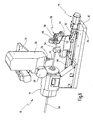
- Fig. 2 shows the machine tool 10 with such a pivoted spindle housing 30.
- the traveling column 32 To the end face 60 of the workpiece 20 of the in Fig. 1 To be able to reach the shown position, the traveling column 32 has also been moved in the X and also in the Z direction.
- the spindle housing 30 relative to its in Fig. 1 shown vertical position has been pivoted by 90 °, so that the tool 22 can engage perpendicular to the end face 60 of the workpiece 20.
- the tool 22 can also pass under the workpiece 20, which is appropriate if the workpiece 20 can not be rotated about its longitudinal axis 17 or instead of a NC rotary spindle 14, a simple clamping bracket is used as a holder.
- the pivot axis 40 is arranged offset to the spindle axis 42 and thus does not intersect.
- this offset is denoted by d;
- dashed lines an alternative arrangement of a pivoting device 38 'is indicated, in which the Swivel axis 40 ', the spindle axis 42 intersects.
- the pivot axis 40 intersects the spindle axis 42 or not, there are different paths of movement for the spindle housing 30 and in particular for the tool 22 accommodated in the tool spindle 26.
- Fig. 4b shows a machine tool in which the pivot axis 40 'intersects the spindle axis 42.
- the tip of the tool 22 also describes a portion of a circular path 62 ', whose radius, however, is slightly smaller than that of the circular path 62. From a comparison of Fig. 4a and 4b It can be seen that the distance s', which travels the tip of the tool 22 in the vertical Z in this case, is greater than the distance s, which is traversed in non-overlapping arrangement of pivot axis 40 and spindle axis 42 in the Z direction. So if the workpiece 20 in a spatial direction and then perpendicular to be processed by the tool 22, so requires in Fig. 4a shown machine tool a smaller travel of the traveling column 32 in the vertical (Z-direction), as in the machine tool according to Fig. 4b the case is. by virtue of This lower travel can reduce the overall height of the machine tool as a whole.
- Fig. 3 also shows that the pivot axis 40 in the front quarter of the spindle housing 30, ie as close as possible to the tool 22 is located. This measure helps to keep the radius of the circular path 62 and thus the required travel paths for the traveling column 32 small. As in Fig. 3 can be seen, however, the pivot axis 40 should also not be arranged too close to the tool 22, since the pivoting device 38 may otherwise be in the processing of the workpiece 20 in the way.
- the Fig. 5a to 5d show the machine tool 10 in plan view, wherein the traveling column 32 is not shown with the spindle housing 30 attached thereto.
- the NC rotary spindle 14 with the workpiece 20 held therein and the carrier 44 which can be moved on rails 64 and 66 in the X direction indicated by 52, can be seen in the plan view.
- the three holders 54, 56 and 58 are arranged eccentrically to the vertical axis 46. The arrangement takes place so that upon rotation of the carrier 44 about the vertical axis 46, the holders 54, 56 and 58 are aligned in their respective machining position coaxial with the NC rotary spindle 14 and to the workpiece 20 held therein.
- the holder 54 which in Fig. 5a is in working position is designed as a quill with a mandrel 68 which holds the workpiece 20 at its end face 60, as is useful, for example, in a turning for centering.
- the holder 56 the in Fig. 5b is in working position, is designed as a steady rest through which the workpiece 20 can be passed.
- the bezel 56 supports the workpiece 20 in such a way that even with larger cutting forces machining in the vicinity of the bezel 56 is possible without resulting bending forces lead to a deformation of the workpiece 20.
- the carrier 44 By moving the carrier 44 in the direction of the arrow 52, the workpiece 20 can be supported where machining is to be performed. In this way, the workpiece 20 is always supported short.
- the holder 58 in the Fig. 5c coaxial with the NC rotary spindle 14 and in Fig. 5d is aligned parallel thereto, is designed as a power clamping bracket, the hydraulically actuated jaws 70 and 72 has.
- a workpiece 20 can be firmly fixed, as is usually required for drilling and milling work.
- the power clamping bracket 58 may also be used to effect the advancement of the workpiece 20 in the X direction. In this way, even longer workpieces can be processed successively.
- the carrier 44 is rotated with the holders mounted thereon in the direction of an arrow 76 by 180 °, whereby the still fixed in the power clamping bracket 58 workpiece part 20 'is pivoted.
- the power clamping bracket 58 thus has two machining positions, namely a coaxial with the first holder and a second parallel thereto.
- a workpiece 20 can be turned without prior separation. It is then only so far by process of the carrier 44 in the X direction 52 to pull out of the NC rotary spindle 14 that it is no longer held by this. Subsequently, the workpiece 20 can then be turned around the vertical axis 46 as described above by turning the carrier 44. Depending on the type of processing u.U. Also, a rotation of the carrier 44 by less than 180 °, e.g. around 90 °. Even then, however, the clamping point or separation point of a processing is at least partially accessible.
- the carrier 44 thus represents a multi-functional platform, can be transferred to the holder with different functions by simply rotating about the vertical axis 46 in a working position. Together with the mobility of the carrier 44 in the X direction 52, this results in a variety of processing options for the workpiece 20.
- the holders 54, 56 and 58 releasably secured to the carrier 44 so that they can be replaced by holders with other functions ,
- the Fig. 6 and 7 show in a perspective view and in a front view of the machine tool 10 in the in Fig. 5a shown processing position.
- an automatic feed device 78 for moving the carrier 44th Die Fig. 6 and 7 show the machine tool 10 during processing a cylindrical workpiece 20 which is clamped in the NC rotary spindle 14 and centered at its free end by means of the mandrel 68 of the sleeve 54.
- the tool 22 is in this case a turning tool.
- the Fig. 8 and 9 show in a perspective view and in plan view, the machine tool 10 in the in Fig. 5b shown processing position.
- the cylindrical workpiece 20 is held here by the NC rotary spindle 14 and the bezel 56.
- the carrier 44 is first moved back, then rotated by 180 ° about the vertical axis 46 and finally moved back to the NC rotary spindle 14 back.
- the carrier 44 with the bezel 56 mounted thereon can be moved synchronously and parallel to the traveling column 32, so that a short support of the workpiece 20 is always ensured.
- Fig. 10 shows the machine tool 10 in a perspective view in a machining position, the in Fig. 5d represented corresponds.
- the end face which has become accessible after turning the workpiece 20 is here machined by a tool 22, the spindle housing being opposite to the one in FIG Fig. 8 shown position was pivoted about 80 °.
Landscapes
- Engineering & Computer Science (AREA)
- Mechanical Engineering (AREA)
- Turning (AREA)
- Machine Tool Units (AREA)
Description
Die Erfindung betrifft eine Werkzeugmaschine zur Bearbeitung eines stangenförmigen Werkstücks, mit einem Fahrständer, an dem eine um eine Spindelachse drehbare Werkzeugspindel befestigt ist, wobei die Werkzeugspindel um eine Schwenkachse verschwenkbar ist, die senkrecht sowohl zu der Spindelachse als auch zu einer Längsachse des Werkstücks angeordnet ist.The invention relates to a machine tool for machining a rod-shaped workpiece, comprising a traveling column, on which a spindle spindle rotatable about a spindle spindle is mounted, wherein the tool spindle is pivotable about a pivot axis which is perpendicular to both the spindle axis and to a longitudinal axis of the workpiece ,
Eine Werkzeugmaschine der eingangs genannten Art ist bekannt aus der
Die bekannte Werkzeugmaschine dient zur Bearbeitung von stangenförmigen Werkzeugmaschinen, die auch um ihre Längsachse gedreht werden können, wozu sie in einen ersten Halter eingespannt sind, aus dem sie mit ihrem zu bearbeitenden Ende hervorstehen. Die Bearbeitung dieses hervorstehenden Endes erfolgt über eine Werkzeugspindel, die an einem Fahrständer angeordnet ist, über den die Werkzeugspindel in drei Achsen verfahrbar ist. Die Werkzeugspindel ist ferner um eine die Spindelachse schneidende Schwenkachse verschwenkbar.The known machine tool is used for processing rod-shaped machine tools, which can also be rotated about its longitudinal axis, for which purpose they are clamped in a first holder, from which they protrude with their end to be machined. The machining of this protruding end via a tool spindle, which is arranged on a traveling column, via which the tool spindle is movable in three axes. The tool spindle is furthermore pivotable about a pivot axis intersecting the spindle axis.
Koaxial zu dem ersten Halter ist ein zweiter Halter vorgesehen, der als Gegenlager für das zu bearbeitende Ende der Werkstoffstange dient.Coaxially with the first holder, a second holder is provided which serves as an abutment for the end of the material rod to be machined.
Aus der
Eine aus der
Nachteilig bei der bekannten Werkzeugmaschine ist, daß entweder nur vergleichsweise kurze Werkstücke in der Werkstückspannvorrichtung in eine vertikale Lage gekippt werden können, um eine Bearbeitung der freien Stirnseite zu ermöglichen, oder aber ein großer Schwenkraum vorgesehen werden muß, der das Verschwenken auch längerer Werkstücke erlaubt.A disadvantage of the known machine tool that either only comparatively short workpieces in the workpiece clamping device can be tilted into a vertical position to allow processing of the free end face, or a large pivot space must be provided, which allows the pivoting even longer workpieces.
Aufgabe der vorliegenden Erfindung ist es daher, eine Werkzeugmaschine der eingangs genannten Art derart zu verbessern, daß mit einer räumlich kompakten Werkzeugmaschine auch längere Werkstücke an ihrer freien Stirnseite bearbeitet werden können.Object of the present invention is therefore to improve a machine tool of the type mentioned in such a way that with a spatially compact machine tool and longer workpieces can be edited at its free end face.
Bei einer Werkzeugmaschine der eingangs genannten Art wird diese Aufgabe erfindungsgemäß dadurch gelöst, daß die Schwenkachse überschneidungsfrei zu der Spindelachse angeordnet ist.In a machine tool of the type mentioned, this object is achieved in that the pivot axis is arranged without overlap to the spindle axis.
Die der Erfindung zugrundeliegende Aufgabe wird auf diese Weise vollkommen gelöst.The problem underlying the invention is completely solved in this way.
Aufgrund der verschwenkbaren Anordnung der Werkzeugspindel kann die freie Stirnfläche des Werkstücks bearbeitet werden, ohne daß das Werkstück geschwenkt werden muß. Dies ist insbesondere bei langen Werkstücken von Vorteil, da der hierfür ansonsten erforderliche Schwenkraum entfallen kann.Due to the pivotable arrangement of the tool spindle, the free end face of the workpiece can be processed without the workpiece has to be pivoted. This is particularly advantageous for long workpieces, since this otherwise required pivot space can be omitted.
Die überschneidungsfreie Anordnung von Schwenkachse und Spindelachse ermöglicht eine konstruktiv einfachere und stabilere Befestigung der Spindel am Fahrständer, da eine zum Verschwenken der Werkzeugspindel vorgesehene Schwenkeinrichtung nicht von der Drehspindel unterbrochen ist. Dies Maßnahme ist im übrigen auch bei solchen Werkzeugmaschinen vorteilhaft, bei denen die Schwenkachse nicht senkrecht zu der Längsachse des Werkstücks, sondern in anderer Weise, insbesondere parallel hierzu, ausgerichtet ist.The non-overlapping arrangement of the pivot axis and spindle axis allows a structurally simpler and more stable attachment of the spindle on the traveling column, as provided for pivoting the tool spindle pivoting device is not interrupted by the rotary spindle. Incidentally, this measure is also advantageous in machine tools in which the pivot axis is not aligned perpendicular to the longitudinal axis of the workpiece, but in another way, in particular parallel thereto.
Bei einer bevorzugten Ausgestaltung der Erfindung ist die Werkzeugspindel um einen Schwenkwinkel von mindestens 90° verschwenkbar.In a preferred embodiment of the invention, the tool spindle is pivotable about a pivot angle of at least 90 °.
Dies hat den Vorteil, daß eine Bearbeitung auch senkrecht zur Stirnfläche des Werkstücks erfolgen kann. Bei Schwenkwinkeln von mehr als 90° kann sogar die Unterseite des Werkstücks von dem Werkzeug erreicht werden, was besonders wichtig ist, falls das Werkstück nicht um seine Längsachse gedreht werden kann.This has the advantage that machining can also be performed perpendicular to the end face of the workpiece. With swing angles greater than 90 °, even the bottom of the workpiece can be reached by the tool, which is particularly important if the workpiece can not be rotated about its longitudinal axis.
Bei einer weiteren bevorzugten Ausgestaltung der Erfindung ist die Werkzeugspindel vorzugsweise zusammen mit einem Antrieb hierfür in einem Spindelgehäuse aufgenommen, wobei die Schwenkachse auf der Höhe der vorderen, eine Werkzeugaufnahme aufweisenden Hälfte, vorzugsweise auf der Höhe des vorderen Viertels des Spindelgehäuses verläuft.In a further preferred embodiment of the invention, the tool spindle is preferably taken together with a drive for this purpose in a spindle housing, wherein the pivot axis at the height of the front, a tool holder having half, preferably at the height of the front quarter of the spindle housing.
Aufgrund des geringen Abstands zwischen Werkzeugaufnahme und Schwenkachse bewegt sich das Werkzeug beim Verschwenken der Werkzeugspindel auf einer Kreisbahn mit kleinem Radius, was zu kurzen Ausgleichsbewegungen des Fahrständers führt, wenn lediglich die Winkellage des Werkzeugs, nicht aber dessen Raumposition als solche verändert werden soll. Zusammen mit der überschneidungsfreien Anordnung von Schwenkachse und Spindelachse lassen auf diese Weise außerdem kurze Verfahrwege des Fahrständers in der Richtung senkrecht zur Längsrichtung des Werkstücks und zur Schwenkachse realisieren. Bei Fahrständermaschinen in der üblichen Ausführung, bei denen sowohl die Werkstücke als auch die Schwenkachse horizontal angeordnet sind, werden durch diese Maßnahme die Verfahrwege in der Vertikalen verkürzt. Folglich benötigt eine derartige Werkzeugmaschine einen geringeren Platzbedarf in der Höhe, die sog. Z-Achse kann also mit geringem Hub ausgelegt werden.Due to the small distance between the tool holder and the pivot axis, the tool moves during pivoting of the tool spindle on a circular path with a small radius, which leads to short compensating movements of the traveling column, if only the angular position of the tool, but not its spatial position should be changed as such. In addition, together with the non-overlapping arrangement of the pivot axis and the spindle axis, short travel paths of the traveling column in the direction perpendicular to the longitudinal direction of the workpiece and the pivot axis can be realized. In traveling column machines in the usual design in which both the workpieces as Also, the pivot axis are arranged horizontally, the travel paths are shortened in the vertical by this measure. Consequently, such a machine tool requires less space in height, the so-called. Z-axis can therefore be designed with a small stroke.
Je kleiner dabei der Abstand zwischen der Schwenkachse und dem Werkzeug ist, desto kleiner ist der Bewegungsradius des Werkzeugs bei der Schwenkbewegung. Allerdings kann die Schwenkachse auch nicht beliebig nahe an dem Werkzeug angeordnet werden, da der Raum um das Werkzeug herum möglichst frei bleiben sollte. Nur dann ist sichergestellt, daß das Werkzeug das Werkstück in allen Lagen ohne Behinderung durch eine für die Verschwenkbarkeit erforderliche Schwenkeinrichtung erreichen und bearbeiten kann. Vorzugsweise befindet sich deswegen eine derartige Schwenkeinrichtung in unmittelbarer Nähe zu einer Stirnfläche des Spindelgehäuses oder schließt sogar bündig mit dieser ab.The smaller the distance between the pivot axis and the tool, the smaller the radius of movement of the tool during the pivoting movement. However, the pivot axis can not be arranged arbitrarily close to the tool, since the space around the tool should remain as free as possible. Only then it is ensured that the tool can reach and work the workpiece in all positions without hindrance by a pivoting device required for the pivotability. Preferably, therefore, such a pivoting device is in close proximity to an end face of the spindle housing or even flush with this.
Besonders bevorzugt ist es außerdem, wenn die Werkzeugmaschine einen ersten und einen zweiten Halter zur Aufnahme des Werkstücks aufweist, wobei der zweite Halter in einer Bearbeitungsstellung koaxial zu dem ersten Halter ausgerichtet und um eine zu einer Längsachse des Werkstücks senkrechte Achse dreh- oder verschwenkbar angeordnet ist.It is also particularly preferred if the machine tool has a first and a second holder for receiving the workpiece, wherein the second holder is aligned in a machining position coaxial with the first holder and arranged rotatable or pivotable about an axis perpendicular to a longitudinal axis of the workpiece axis ,
Aufgrund der Dreh- oder Verschwenkbarkeit des zweiten Halters kann das darin aufgenommene Werkstück soweit von dem ersten Halter wegbewegt werden, daß auch die Einspannstelle einer Bearbeitung durch ein in die Werkzeugspindel eingesetztes Werkzeug zugänglich wird. Um das Werkstück drehen oder verschwenken zu können, kann dieses bspw. vorher an einer Stelle zwischen dem ersten Halter und dem zweiten Halter durchtrennt worden sein, z.B. durch Fräsen oder Sägen. Das Werkstück kann aber auch unzertrennt, d.h. als Ganzes, mit dem zweiten Halter gedreht oder verschwenkt werden, wenn es zuvor vollständig aus dem ersten Halter herausgeschoben wird. Dies kann bspw. durch eine an sich bekannte Vorschubeinrichtung oder auch mit Hilfe eines zweiten Werkstücks erfolgen, welches in den ersten Halter eingeführt wird und dabei das zweite Werkstück aus diesem herausschiebt.Due to the rotational or pivoting ability of the second holder, the workpiece received therein can be moved away from the first holder as far as possible so that the clamping point is also accessible for machining by a tool inserted into the tool spindle. In order to rotate or pivot the workpiece, this can, for example, previously at one point between the first holder and the second holder have been severed, for example by milling or sawing. The workpiece can also be undivided, ie, rotated as a whole, with the second holder or pivoted, if it is previously completely pushed out of the first holder. This can be done, for example, by means of a feed device known per se or else with the aid of a second workpiece, which is introduced into the first holder and thereby pushes the second workpiece out of it.
Falls der erste Halter als Rundtisch oder NC-Drehspindel ausgebildet ist, wird außerdem eine Sechs-Seiten-Bearbeitung des Werkstücks möglich, da durch Drehen oder Verschwenken des zweiten Halters auch die Einspannstelle des Werkstücks einer Bearbeitung zugänglich wird. Besonders wichtig ist dieser Aspekt z.B. bei der Bearbeitung von Aluminiumprofilen, da diese häufig überwiegend stirnseitig an beiden Enden zu bearbeiten sind.In addition, if the first holder is formed as a rotary table or NC rotary spindle, a six-sided machining of the workpiece is possible, since by turning or pivoting of the second holder and the clamping point of the workpiece is a machining accessible. This aspect is particularly important, e.g. in the processing of aluminum profiles, as these are often predominantly frontal at both ends to edit.
Da die senkrechte Achse, um die der zweite Halter dreh- oder schwenkbar ist, senkrecht zu der Schwenkachse der Werkzeugspindel angeordnet ist, ist außerdem eine Bearbeitung des Werkstücks in jeder räumlichen Winkellage zwischen Werkzeug und Werkstück möglich. Dies gilt auch für die sechste Seite (Einspannstelle) des Werkstücks. Diese besondere Eigenschaft wird ohne Redundanz, d.h. mit minimalem konstruktiven Aufwand, erzielt.Since the vertical axis about which the second holder is rotatable or pivotable, is arranged perpendicular to the pivot axis of the tool spindle, also a machining of the workpiece in any spatial angular position between the tool and the workpiece is possible. This also applies to the sixth side (clamping point) of the workpiece. This particular feature is provided without redundancy, i. achieved with minimal design effort.
Vorzugsweise wird bei einer Fahrständermaschine die durch das Drehen oder Verschwenken frei gewordene Einspannstelle des Werkstücks von der Werkzeugspindel angefahren und mit dem darin aufgenommenen Werkzeug bearbeitet. Grundsätzlich ist es aber ebenso möglich, den zweiten Halter derart zu verfahren, daß die Einspannstelle des Werkstücks der sich drehenden, aber räumlich ansonsten feststehenden Werkzeugspindel zugestellt wird.Preferably, in a traveling column machine, the clamping point of the workpiece, which has become free as a result of the turning or pivoting, is approached by the tool spindle and processed with the tool received therein. Basically, it is also possible to move the second holder such that the clamping point of the workpiece of the rotating, but spatially otherwise fixed tool spindle is delivered.
Bei einer bevorzugten Weiterbildung dieser Ausgestaltung ist der zweite Halter um wenigstens 180° dreh- oder verschwenkbar.In a preferred embodiment of this embodiment, the second holder is rotatable or pivotable by at least 180 °.
Auf diese Weise kann das von dem zweiten Halter gehaltene Werkstück vollständig gewendet werden, wodurch die Stelle, an der es zuvor in dem ersten Halter gehalten war, besonders gut zugänglich wird. Falls dies erforderlich sein sollte, kann das Werkstück auch mehrfach gewendet werden, so daß die axialen Enden des Werkstückes wechselseitig bearbeitet werden können.In this way, the workpiece held by the second holder can be turned completely, whereby the point where it was previously held in the first holder, is particularly accessible. If necessary, the workpiece can also be turned several times, so that the axial ends of the workpiece can be machined alternately.
Falls der zweite Halter drehbar angeordnet ist, bleibt die koaxiale Ausrichtung zu dem ersten Halter nach der Drehung erhalten. Bei einer Verschwenkbewegung des zweiten Halters um 180° wird hingegen nur noch eine parallele, nicht aber eine koaxiale Ausrichtung zu dem ersten Halter erreicht. Eine Schwenkbewegung ist in vielen Fällen gegenüber einer Drehbewegung vorzuziehen, da auf diese Weise ein von dem zweiten Halter gehaltenes Werkstück nach dem Verschwenken nicht mit einem sich noch in dem ersten Halter befindenden Werkstück, z.B. einem vorher abgetrennten Teil, kollidieren kann.If the second holder is rotatably arranged, the coaxial alignment with the first holder after rotation is maintained. In a pivoting movement of the second holder by 180 °, however, only a parallel, but not a coaxial alignment with the first holder is achieved. In this case, a pivoting movement is in many cases preferable to a rotational movement, since in this way a workpiece held by the second holder after pivoting will not interfere with a workpiece still in the first holder, e.g. a previously separated part, can collide.
Es ist deswegen besonders bevorzugt, wenn der zweite Halter zur Erzielung einer Schwenkbewegung exzentrisch zu der senkrechten Achse angeordnet ist. Die senkrechte Achse schneidet somit die Längsachse des Werkstücks nicht.It is therefore particularly preferred if the second holder is arranged to achieve a pivoting movement eccentric to the vertical axis. The vertical axis thus does not intersect the longitudinal axis of the workpiece.
Bei einer bevorzugten Weiterbildung dieser Ausgestaltung ist der zweite Halter auf einem um die senkrechte Achse drehbaren Träger angeordnet. Auf dem Träger ist außerdem wenigstens ein weiterer Halter exzentrisch zu der senkrechten Achse angeordnet, so daß der weitere Halter durch Drehen des Trägers um die senkrechte Achse in eine zu dem ersten Halter koaxiale Lage überführbar ist.In a preferred development of this embodiment, the second holder is arranged on a support rotatable about the vertical axis. On the support at least one further holder is arranged eccentrically to the vertical axis, so that the further holder can be converted by rotating the carrier about the vertical axis in a position coaxial with the first holder.
Auf diese Weise können mehrere, ggf. unterschiedliche Halter durch eine einfache Drehbewegung des Trägers zur Aufnahme von Werkstücken zur Verfügung gestellt werden. Durch Drehen des Trägers um die senkrechte Achse wird der ausgewählte Halter koaxial fluchtend zu dem ersten Halter ausgerichtet. Das Werkstück kann dann z.B. durch Verschub in seiner Längsrichtung in diesen ausgewählten Halter eingeführt und anschließend weiter bearbeitet werden. Es können auch gleichartige Halter auf dem Träger angeordnet sein. Dies ist z.B. dann zweckmäßig, wenn während der Bearbeitung eines gewendeten Werkstückes ein anderes Werkstück bereits wieder in einen weiteren Halter eingeführt werden soll.In this way, several, possibly different holders can be provided by a simple rotational movement of the carrier for receiving workpieces available. By rotating the carrier about the vertical axis, the selected holder is aligned coaxially with the first holder. The workpiece may then be e.g. be introduced by displacement in its longitudinal direction in this selected holder and then further processed. It can also be arranged on the carrier similar holders. This is e.g. then useful when another workpiece is to be reintroduced into another holder during the processing of a turned workpiece.
Besonders bevorzugt ist es aber, wenn die weiteren Halter unterschiedlich, insbesondere als Lünette, als Pinole oder als Kraftspannbock, ausgebildet sind.It is particularly preferred, however, if the other holders are designed differently, in particular as a steady rest, as a sleeve or as a power clamping bracket.
Auf diese Weise wird eine Art Multifunktionsplattform geschaffen, wobei ein Funktionswechsel durch einfaches Drehen des Trägers erfolgt. Ein Halter kann z.B. als Pinole mit einem darin aufgenommenen Dorn ausgebildet sein, wodurch insbesondere beim Drehen mit kleineren Schneidkräften oder bei kurzen Werkstücken eine Zentrierung mit ausreichender Abstützung des Werkstücks ermöglicht wird. Ein anderen Halter kann als Lünette (Setzstock) ausgebildet sein, mit der sich größere Schneidkräfte auch bei der Langdrehbearbeitung abstützen lassen. Die Lünette kann das Werkstück dabei bspw. an drei Umfangspunkten mit festen Backen oder mit Rollen unterstützen. Mit einem als Kraftspannbock ausgebildeten Halter, in dem das Werkstück fest fixiert ist, kann das Werkstück ergriffen und durch Drehen des Trägers gewendet werden. Gerade bei den für Fahrständermaschinen typischen Fräs- oder Bohrbearbeitungen, die eine starre Fixierung des Werkstücks erfordern, ist die Verwendung eines Kraftspannbocks als Halter zweckmäßig.In this way, a kind of multi-functional platform is created, whereby a function change takes place by simply turning the carrier. A holder may be formed, for example, as a quill with a mandrel received therein, which in particular when turning with smaller cutting forces or short workpieces centering with sufficient support of the workpiece is possible. Another holder can be designed as a steady rest (butt), with which larger cutting forces can also be supported during long turning. The steady rest can support the workpiece, for example, at three circumferential points with fixed jaws or with rollers. With a designed as a power clamping bracket holder in which the workpiece is firmly fixed, the workpiece can be gripped and turned by turning the carrier. Especially in the case of milling machine or boring operations which are typical for traveling column machines and which require a rigid fixation of the workpiece, the use of a power clamping bracket as a holder is expedient.
Vorzugsweise sind die Halter lösbar an dem Träger befestigt, so daß sie gegen Halter mit anderen Funktionen austauschbar sind. Aufgrund dieses modularen Aufbaus kann die Multifunktionsplattform an unterschiedlichste Anforderungen angepaßt werden.Preferably, the holders are releasably secured to the carrier so that they are interchangeable with holders having other functions. Due to this modular design, the multifunction platform can be adapted to a wide variety of requirements.
Besonders bevorzugt ist es außerdem, wenn der erste Halter gegenüber der Werkzeugmaschine raumfest und der zweite Halter parallel zu der Längsachse des Werkstücks verfahrbar angeordnet ist.In addition, it is particularly preferred if the first holder is spatially fixed relative to the machine tool and the second holder is arranged to be movable parallel to the longitudinal axis of the workpiece.
Dies hat den Vorteil, daß der zweite Halter, der zu diesem Zweck vorzugsweise als Lünette ausgebildet ist, stets in unmittelbare Nähe zu der momentanen Bearbeitungsstelle verfahren werden kann. Auf diese Weise läßt sich das Werkstück stets optimal kurz abstützen, so daß auftretende Biegemomente nicht zu einer Verformung des Werkstücks führen. Die Verfahrbarkeit eröffnet ferner die Möglichkeit, den zweiten Halter, ggf. zusammen mit einem Träger, auf dem er mit weiteren Haltern befestigt ist, so weit aus dem möglichen Bearbeitungsbereich herauszufahren, daß er die Bearbeitung eines in dem ersten Halter aufgenommenen Werkstücks nicht behindert.This has the advantage that the second holder, which is preferably designed for this purpose as a steady rest, can always be moved in the immediate vicinity of the current processing point. In this way, the workpiece can always optimally short support, so that bending moments occurring do not lead to a deformation of the workpiece. The mobility also opens up the possibility of the second holder, possibly together with a carrier on which it is attached with other holders, so far out of the possible processing area, that it does not hinder the machining of a workpiece received in the first holder.
Falls der zweite Halter eine feste Fixierung des Werkstücks in Längsrichtung ermöglicht, wie dies z.B. bei einem Kraftspannbock der Fall ist, so kann dieser auch als Vorschubeinheit für das Werkstück verwendet werden. Somit lassen sich z.B. Abschnitte des Werkstücks sukzessive bearbeiten, indem nach Bearbeitung eines Abschnitts das Werkstück um eine entsprechende Abschnittslänge vorgeschoben und die Bearbeitung an dem nächsten Abschnitt fortgesetzt wird, wobei das Werkstück stets auch von dem ersten Halter gehalten bleibt. Auf diese Weise lassen sich auch solche Werkstücke bearbeiten, die länger als der von dem Fahrständer erreichbare Bearbeitungsbereich sind. Die Länge des Werkstücks kann sogar größer als die Breite der Werkzeugmaschine sein, sofern ein ggf. vorhandenes Maschinengehäuse geeignete Öffnungen zum Durchtritt der Werkstücke aufweist.If the second holder allows a fixed fixation of the workpiece in the longitudinal direction, as e.g. is the case with a power clamp, so this can also be used as a feed unit for the workpiece. Thus, e.g. Successively machining portions of the workpiece by advancing the workpiece by a corresponding section length after machining a section and the processing is continued at the next section, wherein the workpiece always also remains held by the first holder. In this way, also such workpieces can be processed, which are longer than the achievable by the traveling column processing area. The length of the workpiece may even be greater than the width of the machine tool, provided that a possibly present machine housing has suitable openings for the passage of the workpieces.
Der erste Halter kann ebenfalls als Kraftspannbock ausgeführt sein. Dies ist etwa dann zweckmäßig, wenn lediglich eine Bearbeitung des Werkstücks an seiner zu der Werkzeugspindel weisenden Längsseite vorgesehen ist, so daß keine Drehung des Werkstücks um seine Längsachse erforderlich ist.The first holder can also be designed as a power clamping bracket. This is expedient if only one machining of the workpiece is provided on its pointing to the tool spindle longitudinal side, so that no rotation of the workpiece about its longitudinal axis is required.
Vorzugsweise jedoch ist der erste Halter als Drehspindel ausgebildet.Preferably, however, the first holder is designed as a rotary spindle.
Auf diese Weise ist eine Drehbearbeitung des Werkstücks möglich. Anstelle der Drehspindel kann auch ein Rundtisch als erster Halter verwendet werden, der eine winkelgenaue Zustellung und damit eine Vier-Seiten-Bearbeitung des darin gehaltenen Werkstücks erlaubt. Als erster Halter kommt auch eine NC-Drehspindel in Betracht, die die Eigenschaften einer Drehspindel mit denen eines Rundtisches, d.h. hohe Umdrehungszahlen und winkelgenaue Positionierung, vereint.In this way, a turning of the workpiece is possible. Instead of the rotary spindle and a rotary table can be used as the first holder, the angular exact delivery and thus a four-sided processing of the held therein Workpiece allowed. The first holder is also an NC rotary spindle into consideration, which combines the properties of a rotary spindle with those of a rotary table, ie high rotational speeds and angular positioning.
Es versteht sich, daß die vorstehend genannten und die nachstehend noch zu erläuternden Merkmale nicht nur in der jeweils angegebenen Kombination, sondern auch in anderen Kombinationen oder in Alleinstellung verwendbar sind, ohne den Rahmen der vorliegenden Erfindung zu verlassen.It is understood that the features mentioned above and those yet to be explained not only in the particular combination given, but also in other combinations or alone, without departing from the scope of the present invention.
Weitere Merkmale und Vorteile der Erfindung ergeben sich aus der nachfolgenden Beschreibung eines Ausführungsbeispiels der Erfindung anhand der Zeichnung. Darin zeigen:
- Fig. 1
- eine Seitenansicht wichtiger Baugruppen einer erfindungsgemäßen Werkzeugmaschine in vereinfachter schematischer Darstellung;
- Fig. 2
- die Werkzeugmaschine aus
Fig. 1 mit verschwenkter Werkzeugspindel; - Fig. 3
- eine Seitenansicht eines Spindelgehäuse der in
Fig. 1 gezeigten Werkzeugmaschine, in der unterschiedliche Anordnungen einer Schwenkachse angedeutet sind; - Fig. 4a und 4b
- Bewegungsbahnen von Werkzeugen beim Verschwenken für die beiden in
Fig. 3 gezeigten Anordnungen der Schwenkachse; - Fig. 5a bis 5d
- eine Draufsicht auf die in
Fig. 1 gezeigte Werkzeugmaschine in vereinfachter schematischer Darstellung, in der eine Multifunktionsplattform mit mehreren Haltern in unterschiedlichen Drehpositionen erkennbar ist; - Fig. 6
- die in
Fig. 1 gezeigte Werkzeugmaschine in einer perspektivischen Darstellung, bei derFig. 5a entsprechend ein stangenförmiges Werkstück zwischen einer NC-Drehspindel und einer Pinole gehalten ist; - Fig. 7
- die in
Fig. 6 gezeigte Werkzeugmaschine in einer Vorderansicht; - Fig. 8
- die in
Fig. 1 gezeigte Werkzeugmaschine in einer perspektivischen Darstellung, bei derFig. 5b entsprechend ein stangenförmiges Werkstück von einer NC-Drehspindel und einer Lünette gehalten ist; - Fig. 9
- die in
Fig. 8 gezeigte Werkzeugmaschine in Draufsicht; - Fig. 10
- die in
Fig. 1 gezeigte Werkzeugmaschine in einer perspektivischen Darstellung, bei derFig. 5d entsprechend ein stangenförmiges Werkstück von einer NC-Drehspindel und einem um 180° gewendeten Kraftspannbock gehalten wird.
- Fig. 1
- a side view of important components of a machine tool according to the invention in a simplified schematic representation;
- Fig. 2
- the machine tool off
Fig. 1 with swiveled tool spindle; - Fig. 3
- a side view of a spindle housing of in
Fig. 1 shown machine tool in which different arrangements of a pivot axis are indicated; - Fig. 4a and 4b
- Trajectories of tools when pivoting for the two in
Fig. 3 shown arrangements of the pivot axis; - Fig. 5a to 5d
- a top view of the in
Fig. 1 shown machine tool in a simplified schematic representation in which a multi-functional platform with multiple holders in different rotational positions can be seen; - Fig. 6
- in the
Fig. 1 shown machine tool in a perspective view, in theFig. 5a according to a rod-shaped workpiece between an NC rotary spindle and a quill is held; - Fig. 7
- in the
Fig. 6 shown machine tool in a front view; - Fig. 8
- in the
Fig. 1 shown machine tool in a perspective view, in theFig. 5b correspondingly, a rod-shaped workpiece is held by an NC rotary spindle and a steady rest; - Fig. 9
- in the
Fig. 8 shown machine tool in plan view; - Fig. 10
- in the
Fig. 1 shown machine tool in a perspective view, in theFig. 5d Accordingly, a rod-shaped workpiece by an NC rotary spindle and a 180 ° turned power clamp is held.
Die Bearbeitung des Werkstücks 20 erfolgt mit einem Werkzeug 22, das in einer Werkstückaufnahme 24 einer Werkzeugspindel 26 aufgenommen ist. Die Werkzeugspindel 26 ist zusammen mit einem in
Die Werkzeugspindel 26 ist mit dem Spindelgehäuse 30 verschwenkbar an einem Fahrständer 32 befestigt, der in alle drei Raumrichtungen, d.h. in der Höhe Z sowie in beiden horizontalen Raumrichtungen X und Y verfahrbar ist. Die Verschwenkbarkeit des Spindelgehäuses 30 gegenüber dem Fahrständer 32 wird durch eine Schwenkeinrichtung 38 ermöglicht, die bspw. eine sich über die gesamte Ausdehnung des Spindelgehäuses 30 in Y-Richtung erstreckende Schwenkwelle aufweisen kann. Die Schwenkeinrichtung 38 legt eine Schwenkachse 40 fest, die in Y-Richtung, d.h. senkrecht sowohl zur Längsachse 17 des Werkstücks 20 als auch zu einer Spindelachse 42 verläuft, um die herum die Werkzeugspindel 26 durch den Antrieb 28 in Drehung versetzt wird.The
Die Werkzeugmaschine 10 weist ferner einen Träger 44 auf, der um eine zu der vertikalen Längsachse 17 des Werkstücks 20 senkrechte Achse 46 motorisch gedreht werden kann, wie dies in
Auf dem Träger 44 sind drei Halter 54, 56 und 58 angeordnet, die in der Art eines Gegenlagers das Werkstück 20 halten oder abstützen. Nähere Einzelheiten zu den Haltern 54, 56 und 58 werden weiter unten anhand der
Bei einer auf der Fahrständermaschine 10 ebenfalls möglichen Drehbearbeitung des Werkstücks 20 wird dieses von der NC-Drehspindel 14 in Drehung versetzt, während ein geeignetes Werkzeug 22, z.B. ein Drehmeißel, das Werkstück 20 profiliert. Die Werkzeugspindel 26, in die dieses Werkzeug eingespannt ist, ist zu diesem Zweck arretiert, so daß sie sich nicht drehen kann. Der Fahrständer 32 bewegt sich dabei mit der daran befestigten Werkzeugspindel 26 sowohl in Z- als auch in X-Richtung. Bei anderen spanabhebenden Bearbeitungen, z.B. Bohren oder Fräsen auf der Umfangsfläche des Werkstücks 20, wird dieses mit Hilfe der NC-Drehspindel 14 zunächst in die gewünschte Winkellage überführt und anschließend mit einem geeigneten Werkzeug 22 bearbeitet, das durch die Werkzeugspindel 26 in Drehung versetzt wird.In a likewise on the traveling
Falls das Werkstück 20 an seiner Stirnfläche 60 bearbeitet werden soll, wird das Spindelgehäuse 30 um die Schwenkachse 40 so weit geschwenkt, bis die Werkzeugspindel 26 die gewünschte Winkellage zu der Längsachse 17 des Werkstücks 20 eingenommen hat.If the
Bei der in
Diese Bewegungsbahnen sind in den
Aus
Die
Der Halter 54, der in
Der Halter 56, der in
Der Halter 58, der in den
Zum Wenden des Werkstückes 20 wird dieses zunächst an der durch einen Pfeil 74 in
Selbstverständlich kann ein Werkstück 20 auch ohne vorhergehendes Trennen gewendet werden. Es ist dann lediglich soweit durch Verfahren des Trägers 44 in der X-Richtung 52 aus der NC-Drehspindel 14 herauszuziehen, daß es nicht mehr von dieser gehalten wird. Anschließend kann das Werkstück 20 dann wie soeben beschrieben durch Drehen des Trägers 44 um die senkrechte Achse 46 gewendet werden. Je nach Art der Bearbeitung genügt u.U. auch eine Drehung des Trägers 44 um weniger als 180°, z.B. um 90°. Selbst dann wird aber auch die Einspannstelle bzw. Trennstelle einer Bearbeitung zumindest teilweise zugänglich.Of course, a
Der Träger 44 stellt somit eine Multifunktionsplattform dar, auf der Halter mit unterschiedlichen Funktionen durch einfaches Drehen um die senkrechte Achse 46 in eine Arbeitsposition überführt werden können. Zusammen mit der Verfahrbarkeit des Trägers 44 in der X-Richtung 52 ergeben sich dadurch vielfältige Bearbeitungsmöglichkeiten für das Werkstück 20. Vorzugsweise sind die Halter 54, 56 und 58 lösbar an dem Träger 44 befestigt, so daß sie gegen Halter mit anderen Funktionen ausgetauscht werden können.The
Die
Die
Claims (10)
- Machine tool for machining a rod-shaped workpiece (20), having a traveling column (32) to which a tool spindle (26) rotatable about a spindle axis (42) is fastened, whereby the tool spindle (26) is swivelable about a swiveling axis (40) which is arranged perpendicularly to both the spindle axis (42) and a longitudinal axis (17) of the workpiece (20), characterized in that the swiveling axis (40) is arranged so as not to intersect the spindle axis (42).
- Machine tool according to Claim 1, characterized in that the tool spindle (26) is swivelable by a swivel angle of at least 90°.
- Machine tool according to Claim 1 or 2, characterized in that the tool spindle (26), preferably together with a drive (28) for it, is arranged inside a spindle housing (30), and in that the swiveling axis (40) runs at the level of the front half, having a tool holding fixture (24), preferably at the level of the front quarter of the spindle housing (30).
- Machine tool according to anyone of the preceding claims, characterized by a first holder (14) and a second holder (54, 56, 58) for accommodating the workpiece (20), the second holder (54, 56, 58), in a machining position, being oriented coaxially to the first holder (14) and being arranged so as to be rotatable or swivelable about an axis (46) perpendicular to a longitudinal axis (17) of the workpiece (20).
- Machine tool according to Claim 4, characterized in that the second holder (54, 56, 58) is rotatable or swivelable by at least 180°.
- Machine tool according to Claim 4 or 5, characterized in that the second holder (54, 56, 58), for achieving a swiveling movement, is arranged eccentrically to the perpendicular axis (46).
- Machine tool according to Claim 6, characterized in that the second holder (54, 56, 58) is arranged on a support (44) rotatable about the perpendicular axis (46), and in that, in addition, at least one further holder (54, 56, 58) is arranged on the support (44) eccentrically to the perpendicular axis (46), so that the further holder (54, 56, 58), by rotation of the support (44) about the perpendicular axis (46), can be shifted into a position coaxial to the first holder (14).
- Machine tool according to Claim 7, characterized in that the further holders (54, 56, 58) are designed differently, in particular as a steady rest (56), as a tailstock quill (54) or as a power-operated clamping block (58).
- Machine tool according to anyone of Claims 4 to 8, characterized in that the first holder (14) is arranged so as to be spatially fixed relative to the machine tool (10), and the second holder (54, 56, 58) is arranged so as to be movable parallel to the longitudinal axis (17) of the workpiece (20).
- Machine tool according to anyone of Claims 4 to 9, characterized in that the first holder (14) is designed as a head spindle.
Applications Claiming Priority (4)
| Application Number | Priority Date | Filing Date | Title |
|---|---|---|---|
| DE10125729 | 2001-05-17 | ||
| DE10125729 | 2001-05-17 | ||
| DE10145673 | 2001-09-10 | ||
| DE10145673A DE10145673A1 (en) | 2001-05-17 | 2001-09-10 | Machine tool for machining a bar-shaped workpiece |
Publications (3)
| Publication Number | Publication Date |
|---|---|
| EP1260310A2 EP1260310A2 (en) | 2002-11-27 |
| EP1260310A3 EP1260310A3 (en) | 2006-03-15 |
| EP1260310B1 true EP1260310B1 (en) | 2008-04-23 |
Family
ID=26009407
Family Applications (1)
| Application Number | Title | Priority Date | Filing Date |
|---|---|---|---|
| EP02010776A Expired - Lifetime EP1260310B1 (en) | 2001-05-17 | 2002-05-15 | Machine tool for working an elongated workpiece |
Country Status (4)
| Country | Link |
|---|---|
| US (1) | US6836941B2 (en) |
| EP (1) | EP1260310B1 (en) |
| JP (1) | JP4323135B2 (en) |
| DE (1) | DE50212129D1 (en) |
Families Citing this family (26)
| Publication number | Priority date | Publication date | Assignee | Title |
|---|---|---|---|---|
| JP4061164B2 (en) * | 2002-10-07 | 2008-03-12 | 株式会社森精機製作所 | Center misalignment detection device, centering device, and accuracy analysis device including the centering device |
| ITTO20030632A1 (en) * | 2003-08-11 | 2005-02-12 | Comau Spa | MECHANICAL MACHINING UNIT WITH CHIP REMOVAL, |
| US7588397B2 (en) * | 2005-08-31 | 2009-09-15 | Ingersoll Cm Systems Llc | Method and apparatus for machining crankshafts or camshafts |
| US20070044620A1 (en) * | 2005-08-31 | 2007-03-01 | Chun-Yin Lin | Rotary cutting and clamping device for a processing machine |
| DE102005042545B4 (en) * | 2005-09-07 | 2014-05-15 | Feinmechanik Michael Deckel Gmbh & Co Kg | Method for two-side machining of workpieces in an automatic machine tool, and automatic machine tool for carrying out the method |
| JP4451381B2 (en) * | 2005-12-02 | 2010-04-14 | ヤマザキマザック株式会社 | NC machining program creation method and NC machining program creation device of NC machining apparatus |
| DE102006007700A1 (en) * | 2006-02-13 | 2007-08-16 | Stama Maschinenfabrik Gmbh | Machine tool and method for machining workpieces, in particular metallic workpieces |
| WO2007148620A1 (en) * | 2006-06-19 | 2007-12-27 | Jtekt Corporation | Machine tool with turnable movable section |
| JP5138258B2 (en) | 2007-03-28 | 2013-02-06 | シチズンホールディングス株式会社 | Numerically controlled lathe provided with a guide bush and a method of machining a workpiece using the numerically controlled lathe |
| US9162289B2 (en) | 2011-09-12 | 2015-10-20 | Mazak Corporation | Machine tool apparatus and method |
| ITUD20110192A1 (en) * | 2011-11-28 | 2013-05-29 | Rbm Di Battistutta Enrico & C S A S | EQUIPMENT FOR A TOOL MACHINE |
| JP6145396B2 (en) * | 2013-12-11 | 2017-06-14 | Dmg森精機株式会社 | Machine tool steady rest device |
| EP2963305B1 (en) * | 2014-06-30 | 2019-04-17 | Aktiebolaget SKF | Process for manufacturing a hollow roller, hollow roller obtainable via such a process and roller bearing including such a roller |
| JP6562545B2 (en) * | 2015-07-14 | 2019-08-21 | Dmg森精機株式会社 | lathe |
| ITUB20161232A1 (en) * | 2016-03-02 | 2017-09-02 | Gian Domenico Dimetto | MULTIFUNCTION MACHINE FOR MECHANICAL MACHINING OF COMPLEX PIECES. |
| DE102017115734A1 (en) * | 2017-07-13 | 2019-02-07 | Stama Maschinenfabrik Gmbh | Method for machining workpieces and machine tool for carrying out the method |
| JP7188880B2 (en) * | 2017-12-05 | 2022-12-13 | オークマ株式会社 | Machine Tools |
| JP7158008B2 (en) * | 2018-09-06 | 2022-10-21 | オークマ株式会社 | Recovery mechanism and recovery method for processed product |
| CN109176021B (en) * | 2018-10-24 | 2023-12-15 | 成都西菱动力科技股份有限公司 | Belt pulley hole key mark composite automatic processing system |
| CN109434471B (en) * | 2018-12-13 | 2023-09-19 | 浙江日发航空数字装备有限责任公司 | Special equipment for full-automatic turning and milling combined machining of long cylindrical workpiece |
| DE102019203790A1 (en) * | 2019-03-20 | 2020-09-24 | Emco Magdeburg Gmbh | Machine tool and dragging frame conveyor for the supply / removal of workpieces |
| KR102253325B1 (en) * | 2020-03-03 | 2021-05-18 | 김옥현 | Jig for supporting head of eject pin, apparatus for fabricating eject pin with the same, and method for fabricating eject pin using the apparatus for fabricating eject pin |
| CN112975354A (en) * | 2021-02-12 | 2021-06-18 | 翁晓炜 | Automatic processing device for aluminum alloy door and window tube profiles |
| CN113182909B (en) * | 2021-05-08 | 2023-03-21 | 安徽朗轶工业自动化系统有限公司 | Motor shell machining device and machining process thereof |
| CN115256064B (en) * | 2022-06-25 | 2024-01-09 | 上海惠而顺精密工具股份有限公司 | Tool for machining long rod cutter |
| CN114850547B (en) * | 2022-07-11 | 2022-10-25 | 成都飞机工业(集团)有限责任公司 | Carbon fiber member contour milling damage inhibition method |
Family Cites Families (22)
| Publication number | Priority date | Publication date | Assignee | Title |
|---|---|---|---|---|
| US2281353A (en) * | 1939-02-20 | 1942-04-28 | Russel R Fray | Full universal all-speed milling attachment |
| US2275291A (en) * | 1939-04-04 | 1942-03-03 | Rudolph F Bannow | Machine tool operating at universal angles in overall locations |
| US2619879A (en) * | 1946-07-22 | 1952-12-02 | Kaukauna Machine Corp | Machine tool |
| US3083617A (en) * | 1958-02-13 | 1963-04-02 | Sundstrand Corp | Machine tool |
| US3359861A (en) * | 1965-08-17 | 1967-12-26 | Ford Motor Co | Five axis milling machine |
| US3371580A (en) | 1966-01-21 | 1968-03-05 | Mc Donnell Douglas Corp | Multiple axis milling machine and fixture |
| US3577828A (en) * | 1969-04-17 | 1971-05-04 | Gulf & Western Precision Engin | Milling machine |
| US3570369A (en) * | 1969-06-06 | 1971-03-16 | Textron Inc | Tool-carrying turret |
| US3806691A (en) * | 1972-11-20 | 1974-04-23 | Cammann Mfg Co | Tool positioner |
| FR2552002B1 (en) * | 1983-09-15 | 1987-07-31 | Forest Line Sa | MILLING DEVICE WITH UNIVERSAL RETURN AND AUTOMATIC INDEXING |
| JPS6061101U (en) * | 1983-09-30 | 1985-04-27 | 三菱重工業株式会社 | Machine tool healing attachment |
| JPH035407Y2 (en) * | 1985-06-07 | 1991-02-12 | ||
| GB2215243B (en) * | 1988-02-24 | 1992-02-26 | Jobs Spa | A chuck head for automatic machine tools. |
| JPH01222809A (en) * | 1988-02-26 | 1989-09-06 | Shin Nippon Koki Kk | Machine tool |
| DE3824602A1 (en) | 1988-07-19 | 1990-01-25 | Rheinische Maschinenfabrik & E | Machine for machining cubic and rotationally symmetric workpieces |
| IT1265927B1 (en) * | 1993-01-15 | 1996-12-16 | Jobs Spa | INDEXED OPERATING HEAD FOR AUTOMATIC MACHINE TOOLS. |
| US5429345A (en) | 1993-05-27 | 1995-07-04 | Yang; Tai-Her | Rotary disc positioner with axial displacement |
| FR2711932B1 (en) * | 1993-11-04 | 1996-03-01 | Line Henri | Tool holder device, in particular milling head, with adjustable spindle holder. |
| DE59602087D1 (en) | 1996-04-03 | 1999-07-08 | Hermle Berthold Maschf Ag | Drilling and / or milling machine |
| JP2788231B2 (en) * | 1996-09-04 | 1998-08-20 | 川崎重工業株式会社 | Long bar material processing apparatus and processing method |
| DE19919647C2 (en) | 1999-04-30 | 2003-08-21 | Stama Maschinenfabrik Gmbh | Machine tool with a manipulator |
| EP1155764B1 (en) * | 1999-10-28 | 2007-12-12 | Nakamura-Tome Precision Ind. Co., Ltd. | Combined nc lathe |
-
2002
- 2002-05-15 DE DE50212129T patent/DE50212129D1/en not_active Expired - Lifetime
- 2002-05-15 EP EP02010776A patent/EP1260310B1/en not_active Expired - Lifetime
- 2002-05-16 US US10/147,126 patent/US6836941B2/en not_active Expired - Lifetime
- 2002-05-16 JP JP2002141349A patent/JP4323135B2/en not_active Expired - Fee Related
Also Published As
| Publication number | Publication date |
|---|---|
| JP4323135B2 (en) | 2009-09-02 |
| US20020189063A1 (en) | 2002-12-19 |
| JP2003025101A (en) | 2003-01-29 |
| DE50212129D1 (en) | 2008-06-05 |
| EP1260310A2 (en) | 2002-11-27 |
| EP1260310A3 (en) | 2006-03-15 |
| US6836941B2 (en) | 2005-01-04 |
Similar Documents
| Publication | Publication Date | Title |
|---|---|---|
| EP1260310B1 (en) | Machine tool for working an elongated workpiece | |
| EP1260307B1 (en) | Machine tool and method of working an elongated workpiece | |
| EP1982799B1 (en) | Handling device | |
| DE19635258C1 (en) | Boring and milling machine for processing material bars | |
| EP1027955B1 (en) | Machine tool | |
| DE2615137C2 (en) | Turret lathe | |
| EP1004393B1 (en) | Machine tool arrangment with a device for automatic tool-change | |
| DE19919645A1 (en) | Machine tool for drilling and cutting, has turning tool mounted in clamp separate from spindle | |
| DE102008060297B3 (en) | lathe | |
| EP0154349B1 (en) | Device for exchanging tools or the like at the spindle of a machine tool | |
| WO1996024465A1 (en) | Multiple-spindle lathe | |
| EP1651381B1 (en) | Machine tool comprising a clamping device on both sides | |
| EP3081324A1 (en) | Long turning machine with two nc-controlled processing axes and method for machining workpieces on a long turning machine with two nc-controlled processing axes | |
| DE10145674B4 (en) | Machine tool to work rod-shaped workpieces has an initial workpiece holder, for machining in one position, and a second rotating or swing holder to move the workpiece into a further working position | |
| EP1025953B1 (en) | Machine tool | |
| DE10130760A1 (en) | Machine tool with rotatable multiple tool carrier has tool carrier head axis running transversely to plane passing through transverse motion axis and longitudinal motion axis | |
| EP0787560B1 (en) | Device for working bars, profiles and the like | |
| DE29821047U1 (en) | Machine tool arrangement with a device for an automatic tool change | |
| DE102004019936B4 (en) | Lathe, in particular multi-spindle automatic lathe | |
| EP0755315A1 (en) | Multiple-spindle lathe | |
| DE10109117C1 (en) | Burr removing device for conical gears has slotting tool guided and moved by two numerically controllable axes | |
| DE102005030548B4 (en) | Machine tool for machining bar-shaped workpieces | |
| DE10031460B4 (en) | Clamping and positioning device, especially for long and thin workpieces | |
| DE2544074C2 (en) | Device on a multi-spindle automatic lathe for milling slots in workpieces | |
| DE29820630U1 (en) | Feeding device for at least one workpiece on a processing machine |
Legal Events
| Date | Code | Title | Description |
|---|---|---|---|
| PUAI | Public reference made under article 153(3) epc to a published international application that has entered the european phase |
Free format text: ORIGINAL CODE: 0009012 |
|
| AK | Designated contracting states |
Kind code of ref document: A2 Designated state(s): AT BE CH CY DE DK ES FI FR GB GR IE IT LI LU MC NL PT SE TR |
|
| AX | Request for extension of the european patent |
Free format text: AL;LT;LV;MK;RO;SI |
|
| PUAL | Search report despatched |
Free format text: ORIGINAL CODE: 0009013 |
|
| AK | Designated contracting states |
Kind code of ref document: A3 Designated state(s): AT BE CH CY DE DK ES FI FR GB GR IE IT LI LU MC NL PT SE TR |
|
| AX | Request for extension of the european patent |
Extension state: AL LT LV MK RO SI |
|
| RIC1 | Information provided on ipc code assigned before grant |
Ipc: B23Q 1/62 20060101ALI20060120BHEP Ipc: B23Q 1/76 20060101ALI20060120BHEP Ipc: B23Q 7/04 20060101AFI20060120BHEP |
|
| 17P | Request for examination filed |
Effective date: 20060505 |
|
| 17Q | First examination report despatched |
Effective date: 20060718 |
|
| 17Q | First examination report despatched |
Effective date: 20060718 |
|
| AKX | Designation fees paid |
Designated state(s): DE ES IT |
|
| GRAP | Despatch of communication of intention to grant a patent |
Free format text: ORIGINAL CODE: EPIDOSNIGR1 |
|
| GRAS | Grant fee paid |
Free format text: ORIGINAL CODE: EPIDOSNIGR3 |
|
| GRAA | (expected) grant |
Free format text: ORIGINAL CODE: 0009210 |
|
| AK | Designated contracting states |
Kind code of ref document: B1 Designated state(s): DE ES IT |
|
| REF | Corresponds to: |
Ref document number: 50212129 Country of ref document: DE Date of ref document: 20080605 Kind code of ref document: P |
|
| REG | Reference to a national code |
Ref country code: ES Ref legal event code: FG2A Ref document number: 2304407 Country of ref document: ES Kind code of ref document: T3 |
|
| PLBE | No opposition filed within time limit |
Free format text: ORIGINAL CODE: 0009261 |
|
| STAA | Information on the status of an ep patent application or granted ep patent |
Free format text: STATUS: NO OPPOSITION FILED WITHIN TIME LIMIT |
|
| 26N | No opposition filed |
Effective date: 20090126 |
|
| PG25 | Lapsed in a contracting state [announced via postgrant information from national office to epo] |
Ref country code: IT Free format text: LAPSE BECAUSE OF NON-PAYMENT OF DUE FEES Effective date: 20110515 |
|
| PGRI | Patent reinstated in contracting state [announced from national office to epo] |
Ref country code: IT Effective date: 20130107 |
|
| PGFP | Annual fee paid to national office [announced via postgrant information from national office to epo] |
Ref country code: IT Payment date: 20190527 Year of fee payment: 18 Ref country code: ES Payment date: 20190620 Year of fee payment: 18 |
|
| PGFP | Annual fee paid to national office [announced via postgrant information from national office to epo] |
Ref country code: DE Payment date: 20190702 Year of fee payment: 18 |
|
| REG | Reference to a national code |
Ref country code: DE Ref legal event code: R119 Ref document number: 50212129 Country of ref document: DE |
|
| PG25 | Lapsed in a contracting state [announced via postgrant information from national office to epo] |
Ref country code: DE Free format text: LAPSE BECAUSE OF NON-PAYMENT OF DUE FEES Effective date: 20201201 |
|
| REG | Reference to a national code |
Ref country code: ES Ref legal event code: FD2A Effective date: 20210930 |
|
| PG25 | Lapsed in a contracting state [announced via postgrant information from national office to epo] |
Ref country code: ES Free format text: LAPSE BECAUSE OF NON-PAYMENT OF DUE FEES Effective date: 20200516 |
|
| PG25 | Lapsed in a contracting state [announced via postgrant information from national office to epo] |
Ref country code: IT Free format text: LAPSE BECAUSE OF NON-PAYMENT OF DUE FEES Effective date: 20210531 |