EP1260296B1 - Bohrer - Google Patents
Bohrer Download PDFInfo
- Publication number
- EP1260296B1 EP1260296B1 EP02010169A EP02010169A EP1260296B1 EP 1260296 B1 EP1260296 B1 EP 1260296B1 EP 02010169 A EP02010169 A EP 02010169A EP 02010169 A EP02010169 A EP 02010169A EP 1260296 B1 EP1260296 B1 EP 1260296B1
- Authority
- EP
- European Patent Office
- Prior art keywords
- drill
- helix
- shaft
- area
- smaller
- Prior art date
- Legal status (The legal status is an assumption and is not a legal conclusion. Google has not performed a legal analysis and makes no representation as to the accuracy of the status listed.)
- Expired - Lifetime
Links
- 238000005553 drilling Methods 0.000 claims description 15
- 239000000428 dust Substances 0.000 description 4
- 230000007704 transition Effects 0.000 description 4
- 230000001419 dependent effect Effects 0.000 description 1
- 230000006866 deterioration Effects 0.000 description 1
- 230000000694 effects Effects 0.000 description 1
- 235000013312 flour Nutrition 0.000 description 1
- 238000003754 machining Methods 0.000 description 1
- 239000011435 rock Substances 0.000 description 1
- 239000004575 stone Substances 0.000 description 1
Images


Classifications
-
- B—PERFORMING OPERATIONS; TRANSPORTING
- B23—MACHINE TOOLS; METAL-WORKING NOT OTHERWISE PROVIDED FOR
- B23B—TURNING; BORING
- B23B51/00—Tools for drilling machines
- B23B51/02—Twist drills
-
- B—PERFORMING OPERATIONS; TRANSPORTING
- B28—WORKING CEMENT, CLAY, OR STONE
- B28D—WORKING STONE OR STONE-LIKE MATERIALS
- B28D1/00—Working stone or stone-like materials, e.g. brick, concrete or glass, not provided for elsewhere; Machines, devices, tools therefor
- B28D1/14—Working stone or stone-like materials, e.g. brick, concrete or glass, not provided for elsewhere; Machines, devices, tools therefor by boring or drilling
- B28D1/146—Tools therefor
-
- B—PERFORMING OPERATIONS; TRANSPORTING
- B23—MACHINE TOOLS; METAL-WORKING NOT OTHERWISE PROVIDED FOR
- B23B—TURNING; BORING
- B23B2226/00—Materials of tools or workpieces not comprising a metal
- B23B2226/75—Stone, rock or concrete
-
- B—PERFORMING OPERATIONS; TRANSPORTING
- B23—MACHINE TOOLS; METAL-WORKING NOT OTHERWISE PROVIDED FOR
- B23B—TURNING; BORING
- B23B2251/00—Details of tools for drilling machines
- B23B2251/04—Angles, e.g. cutting angles
- B23B2251/043—Helix angles
-
- B—PERFORMING OPERATIONS; TRANSPORTING
- B23—MACHINE TOOLS; METAL-WORKING NOT OTHERWISE PROVIDED FOR
- B23B—TURNING; BORING
- B23B2251/00—Details of tools for drilling machines
- B23B2251/40—Flutes, i.e. chip conveying grooves
- B23B2251/402—Flutes, i.e. chip conveying grooves with increasing depth in a direction towards the shank from the tool tip
-
- B—PERFORMING OPERATIONS; TRANSPORTING
- B23—MACHINE TOOLS; METAL-WORKING NOT OTHERWISE PROVIDED FOR
- B23B—TURNING; BORING
- B23B2251/00—Details of tools for drilling machines
- B23B2251/40—Flutes, i.e. chip conveying grooves
- B23B2251/404—Flutes, i.e. chip conveying grooves with decreasing depth in a direction towards the shank from the tool tip
-
- B—PERFORMING OPERATIONS; TRANSPORTING
- B23—MACHINE TOOLS; METAL-WORKING NOT OTHERWISE PROVIDED FOR
- B23B—TURNING; BORING
- B23B2251/00—Details of tools for drilling machines
- B23B2251/40—Flutes, i.e. chip conveying grooves
- B23B2251/406—Flutes, i.e. chip conveying grooves of special form not otherwise provided for
-
- B—PERFORMING OPERATIONS; TRANSPORTING
- B23—MACHINE TOOLS; METAL-WORKING NOT OTHERWISE PROVIDED FOR
- B23B—TURNING; BORING
- B23B2251/00—Details of tools for drilling machines
- B23B2251/44—Margins, i.e. the narrow portion of the land which is not cut away to provide clearance on the circumferential surface
- B23B2251/446—Drills with variable margins
Definitions
- the invention relates to a drill according to the preamble of claim 1.
- the invention particularly relates to a hammer drill for machining Stone or concrete.
- the drilling performance of such a drill of a variety depends on parameters, such as pitch of the helix, ratio of Spiral diameter of the drill to core diameter, etc. Furthermore, it is known that the various parameters influence each other so that a Improvement in one area, such as drilling performance, one Deterioration in another area, for example in terms of stability.
- the object of the invention is a drill of the beginning to further develop such a way that new freedoms in the Matching the different parameters are obtained among each other.
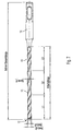
- FIG. 1 shows a drill according to a first embodiment. It has a shaft 10 extending from a drill bit 12 to extends to a drive section 14 received in a tool can be. Along the shaft 10 extends a coil 16 which has a has variable slope. In a front portion L1 of the shaft has the Wendel 16 a large slope, and in a rear section L3 of the Shank, the helix 10 has a smaller pitch. In a middle area L2 of the shaft changes the slope from that in the front section present larger slope to the present in the rear section smaller Pitch. The spiral diameter of the drill and the core diameter are constant along the shaft so that the helix has a constant height.
- the Width of the helix changes according to the slope. In the front section, the helix has a larger one Width, and in the rear section has a smaller width. The big width The helix near the drill bit protects against a large wear the helix, especially if hard concrete or hard rock drilled becomes.
- the working length of the helix is a total of 100 mm with a total length of the drill of 160 mm.
- the Core diameter is 3.9 mm
- the spiral diameter is 5.8 mm.
- the width d 1 of the helix in the rear section is 1.4 mm
- the width d2 the helix in the front section is 2.8 mm.
- the slope of the helix changes between values of 19 and 23 mm.
- FIG. 2 shows a drill according to a second embodiment.
- the helix has its smaller one here Increase in the front section L1 of the shaft, while the greater incline is present in the rear portion L3 of the shaft.
- the spiral diameter and the Core diameters are constant over the shaft. In this design will be accelerates the drilling dust at the drill tip at the front and thus dissipates it faster. The faster removal of the drilling dust results in a better one Drilling progress and a higher drilling speed.
- FIG. 3 shows a drill according to a third embodiment.
- the helix has similar to the first Embodiment a large pitch in the front portion L1 of the shaft and a smaller pitch in the rear portion L3 of the shaft.
- the Spiral diameter of the drill is constant along the shaft.
- FIG. 4 shows a drill according to a fourth embodiment, wherein the helix in the same manner as in the third embodiment a larger pitch in the front portion L1 of the shaft and a smaller pitch in the rear portion L3 of the shaft has.
- third embodiment increases the core diameter of the shaft starting from a smaller value in the area of the drill bit to one greater value in the region of the transition to the drive section.
- the hammering action of the tool which is the drill drives better to be transferred to the drill bit.
- the big width of the helix in the front section reduces wear.
- FIG. 5 shows a drill according to a fifth embodiment.
- the coil in the front portion of the L1 Shank a smaller pitch and in the rear section L3 of the shaft one greater slope.
- the core diameter is like this designed to be of a greater value in the area of the drill bit on one smaller value drops in the region of the transition to the drive section.
- FIG. 6 shows a drill according to a sixth embodiment.
- the pitch of the helix increases from one smaller value in the region of the front portion L1 of the shaft on a greater value in the area of the rear section L3. In this way results in the front area a very good removal of the drilling dust.
- the Core diameter increases from a smaller value in the area of the drill bit a larger value in the area of the transition to the drive section 14 at. In this way, the hammering effect of the tool is better for Transfer drill bit.
- FIG. 7 shows a drill according to a seventh embodiment.
- the core diameter and the spiral diameter are constant.
- the slope of the helix increases from a low value in the front section L 1 to a greater value in the middle section L2 of the Shank and finally sinks back to a lower value in the rear Section L3 of the shaft from.
- the smaller slope of the helix in the area the front portion L1 of the shaft improves the removal of the drilling dust.
- FIG. 8 shows a drill according to an eighth embodiment. Also in this embodiment, the core diameter and the Spiral diameter of the drill constant.
- the slope of the helix sinks starting from a larger value in the front section L1 of the shaft initially to a smaller value in the middle section L2 of the shaft. From this smaller value, it rises again to a larger value in the back Section L3 of the shaft. Due to the correspondingly large width of the helix In the area of the drill bit results in a high wear resistance.
Landscapes
- Engineering & Computer Science (AREA)
- Mechanical Engineering (AREA)
- Mining & Mineral Resources (AREA)
- Processing Of Stones Or Stones Resemblance Materials (AREA)
- Earth Drilling (AREA)
- Drilling Tools (AREA)
Description
- Figur 1 einen erfindungsgemäßen Bohrer gemäß einer ersten Ausführungsform in einer Seitenansicht;
- Figur 2 einen erfindungsgemäßen Bohrer gemäß einer zweiten Ausführungsform in einer Seitenansicht;
- Figur 3 einen erfindungsgemäßen Bohrer gemäß einer dritten Ausführungsform in einer Seitenansicht;
- Figur 4 einen erfindungsgemäßen Bohrer gemäß einer vierten Ausführungsform in einer Seitenansicht;
- Figur 5 einen erfindungsgemäßen Bohrer gemäß einer fünften Ausführungsform in einer Seitenansicht;
- Figur 6 einen erfindungsgemäßen Bohrer gemäß einer sechsten Ausführungsform in einer Seitenansicht;
- Figur 7 einen erfindungsgemäßen Bohrer gemäß einer siebten Ausführungsform in einer Seitenansicht; und
- Figur 8 einen erfindungsgemäßen Bohrer gemäß einer achten Ausführungsform in einer Seitenansicht.
Claims (5)
- Bohrer mit einer Bohrspitze (12), einem Schaft (10), einem Antriebsabschnitt (14) und einer Wendel (16), die sich entlang dem Schaft erstreckt, wobei sich die Geometrie der Wendel (16) entlang dem Schaft ändert, dadurch gekennzeichnet, daß die Breite der Wendel (16), gemessen parallel zur Längsachse des Bohrers, in den Bereichen mit kleiner Steigung der Wendel (16) kleiner ist als in Bereichen mit großer Steigung.
- Bohrer nach Anspruch 1, dadurch gekennzeichnet, daß der Kerndurchmesser des Schaftes (10) im Bereich der Bohrspitze (12) geringer ist als angrenzend an den Antriebsabschnitt (14).
- Bohrer nach Anspruch 1, dadurch gekennzeichnet, daß der Kerndurchmesser des Schaftes (10) im Bereich der Bohrspitze (12) größer ist als angrenzend an den Antriebsabschnitt (14).
- Bohrer nach einem der Ansprüche 1 bis 3, dadurch gekennzeichnet, daß die Steigung der Wendel (16) im Bereich der Bohrspitze (12) größer ist als angrenzend an den Antriebsabschnitt (14).
- Bohrer nach einem der Ansprüche 1 bis 3, dadurch gekennzeichnet, daß die Steigung der Wendel (16) im Bereich der Bohrspitze (12) kleiner ist als angrenzend an den Antriebsabschnitt (14).
Applications Claiming Priority (2)
| Application Number | Priority Date | Filing Date | Title |
|---|---|---|---|
| DE20108179U | 2001-05-15 | ||
| DE20108179U DE20108179U1 (de) | 2001-05-15 | 2001-05-15 | Bohrer |
Publications (2)
| Publication Number | Publication Date |
|---|---|
| EP1260296A1 EP1260296A1 (de) | 2002-11-27 |
| EP1260296B1 true EP1260296B1 (de) | 2005-12-21 |
Family
ID=7956915
Family Applications (1)
| Application Number | Title | Priority Date | Filing Date |
|---|---|---|---|
| EP02010169A Expired - Lifetime EP1260296B1 (de) | 2001-05-15 | 2002-05-14 | Bohrer |
Country Status (3)
| Country | Link |
|---|---|
| EP (1) | EP1260296B1 (de) |
| AT (1) | ATE313407T1 (de) |
| DE (2) | DE20108179U1 (de) |
Cited By (3)
| Publication number | Priority date | Publication date | Assignee | Title |
|---|---|---|---|---|
| US9085074B2 (en) | 2011-03-22 | 2015-07-21 | Black & Decker Inc. | Chisels |
| USD734792S1 (en) | 2013-03-15 | 2015-07-21 | Black & Decker Inc. | Drill bit |
| USD737875S1 (en) | 2013-03-15 | 2015-09-01 | Black & Decker Inc. | Drill bit |
Families Citing this family (14)
| Publication number | Priority date | Publication date | Assignee | Title |
|---|---|---|---|---|
| DE50304177D1 (de) * | 2002-02-28 | 2006-08-24 | Bosch Gmbh Robert | Verfahren zur Herstellung eines Bohrers oder Fräsers |
| EP1628795B1 (de) | 2003-06-04 | 2010-08-18 | Seco Tools AB | Verfahren und vorrichtung zur herstellung eines zuschnitts für ein werkzeug |
| GB2405606A (en) * | 2003-09-08 | 2005-03-09 | Black & Decker Inc | Self-centering drill bit with pilot tip |
| EP1512476B1 (de) * | 2003-09-08 | 2013-10-09 | Black & Decker Inc. | Selbstzentrierendes Bohrwerkzeug mit Pilotschneidteil |
| DE102007042280A1 (de) * | 2007-09-06 | 2009-03-12 | Komet Group Holding Gmbh | Bohrwerkzeug für Werkzeugmaschinen sowie Verfahren zu dessen Herstellung |
| IL211236A0 (en) * | 2011-02-15 | 2011-04-28 | Vladimir Volokh | Rotary cutter |
| DE102011016686A1 (de) | 2011-04-11 | 2012-10-11 | Illinois Tool Works Inc. | Gesteinsbohrer |
| US9333564B2 (en) | 2013-03-15 | 2016-05-10 | Black & Decker Inc. | Drill bit |
| DE102013106614A1 (de) * | 2013-06-25 | 2015-01-08 | Heller Tools Gmbh | Gesteinsbohrer |
| DE102013109796A1 (de) * | 2013-09-06 | 2015-03-12 | Drebo Werkzeugfabrik Gmbh | Bohrer |
| DE102014212714B4 (de) | 2014-07-01 | 2022-02-17 | Kennametal Inc. | Bohrerkopf |
| DE102016221515A1 (de) | 2015-11-09 | 2017-05-11 | Robert Bosch Gmbh | Bohrwerkzeug |
| DE102016214386A1 (de) | 2016-07-14 | 2018-01-18 | MAPAL Fabrik für Präzisionswerkzeuge Dr. Kress KG | Stufenbohrer |
| GB2574652A (en) | 2018-06-14 | 2019-12-18 | Black & Decker Inc | Drilling tool |
Family Cites Families (11)
| Publication number | Priority date | Publication date | Assignee | Title |
|---|---|---|---|---|
| DE3317989A1 (de) | 1983-05-18 | 1984-11-22 | Hawera Probst Gmbh + Co, 7980 Ravensburg | Bohrwerkzeug |
| DE3834675A1 (de) | 1988-10-12 | 1990-04-19 | Hawera Probst Kg Hartmetall | Bohrwerkzeug |
| US5350261A (en) * | 1992-03-12 | 1994-09-27 | Mitsubishi Materials Corporation | Twist drill |
| DE4407119A1 (de) | 1993-12-11 | 1995-06-14 | Hawera Probst Kg Hartmetall | Gesteinsbohrer |
| DE4419641A1 (de) | 1994-06-04 | 1995-12-07 | Hilti Ag | Gesteinsbohrer |
| DE29508159U1 (de) | 1995-05-17 | 1995-08-03 | Halamay, Klaus, Dipl.-Ing. (FH), 86420 Diedorf | Stufenbohrer für Beton und Mauerwerk |
| JPH09277108A (ja) * | 1996-02-14 | 1997-10-28 | Sumitomo Electric Ind Ltd | ドリル |
| US5915485A (en) | 1997-01-13 | 1999-06-29 | Mcatavey; Dennis B. | Ski post hole auger bit |
| DE19707115A1 (de) * | 1997-02-22 | 1998-08-27 | Hilti Ag | Bohr- und/oder Meisselwerkzeug |
| DE29703397U1 (de) | 1997-02-26 | 1997-07-17 | Lorenz, Dieter, Dipl.-Ing., 08144 Stenn | Bohrwerkzeug zur Herstellung von konischen Bohrungen im Bereich der Bearbeitung nichtmetallischer massiver Werkstoffe als Grundlage einer qualitativ hochwertigen Schraubverbindung |
| DE19753731A1 (de) | 1997-12-04 | 1999-06-10 | Hawera Probst Gmbh | Gesteinsbohrwerkzeug |
-
2001
- 2001-05-15 DE DE20108179U patent/DE20108179U1/de not_active Expired - Lifetime
-
2002
- 2002-05-14 AT AT02010169T patent/ATE313407T1/de not_active IP Right Cessation
- 2002-05-14 EP EP02010169A patent/EP1260296B1/de not_active Expired - Lifetime
- 2002-05-14 DE DE50205320T patent/DE50205320D1/de not_active Expired - Fee Related
Cited By (4)
| Publication number | Priority date | Publication date | Assignee | Title |
|---|---|---|---|---|
| US9085074B2 (en) | 2011-03-22 | 2015-07-21 | Black & Decker Inc. | Chisels |
| US9333635B2 (en) | 2011-03-22 | 2016-05-10 | Black & Decker Inc. | Chisels |
| USD734792S1 (en) | 2013-03-15 | 2015-07-21 | Black & Decker Inc. | Drill bit |
| USD737875S1 (en) | 2013-03-15 | 2015-09-01 | Black & Decker Inc. | Drill bit |
Also Published As
| Publication number | Publication date |
|---|---|
| DE20108179U1 (de) | 2001-07-26 |
| DE50205320D1 (de) | 2006-01-26 |
| ATE313407T1 (de) | 2006-01-15 |
| EP1260296A1 (de) | 2002-11-27 |
Similar Documents
| Publication | Publication Date | Title |
|---|---|---|
| EP1260296B1 (de) | Bohrer | |
| EP2237913B1 (de) | Bohrwerkzeug mit ausspitzung | |
| EP0363734B1 (de) | Bohrwerkzeug mit Förderwendel | |
| EP0126409B2 (de) | Bohrwerkzeug | |
| DE69630344T2 (de) | Walzgeschmiedeter Bohrer | |
| EP1259699B1 (de) | Gesteinsbohrer | |
| DE102005005982A1 (de) | Tieflochbohrer | |
| EP0987076A2 (de) | Bohrer | |
| DE19807609A1 (de) | Spiralbohrer | |
| EP1316669A2 (de) | Gesteinbohrwerkzeug | |
| DE4436916A1 (de) | Bohrwerkzeug mit Trägerkörper und Schneidkörpern | |
| DE19942987A1 (de) | Bohrwerkzeug | |
| DE19803304C5 (de) | Bohrgestänge zum Drehschlagbohren, insbesondere zum Überlagerungsbohren | |
| DE1927754C3 (de) | Gesteinsbohrer | |
| DE102007020051B4 (de) | Hartmetallplatte für Gesteinsbohrer und Gesteinsbohrer | |
| EP2845672B1 (de) | Bohrer | |
| DE10351327B4 (de) | Bohrwerkzeug | |
| DE2211532A1 (de) | Bohrer, insbesondere steinbohrer | |
| DE102006062429A1 (de) | Tieflochbohrer mit Stützring und Verfahren zu dessen Herstellung | |
| DE2459286A1 (de) | Spiralbohrer, insbesondere zum bohren weicher werkstoffe | |
| EP3409880B1 (de) | Hybrid-eisbohrer | |
| DE10038039A1 (de) | Bohr- und/oder Meißelwerkzeug | |
| DE102019109587A1 (de) | Stufenbohrer | |
| DE10031968A1 (de) | Bohrer für Gestein | |
| DE102017117664A1 (de) | Bohrer |
Legal Events
| Date | Code | Title | Description |
|---|---|---|---|
| PUAI | Public reference made under article 153(3) epc to a published international application that has entered the european phase |
Free format text: ORIGINAL CODE: 0009012 |
|
| AK | Designated contracting states |
Kind code of ref document: A1 Designated state(s): AT BE CH CY DE DK ES FI FR GB GR IE IT LI LU MC NL PT SE TR |
|
| AX | Request for extension of the european patent |
Free format text: AL;LT;LV;MK;RO;SI |
|
| 17P | Request for examination filed |
Effective date: 20030523 |
|
| AKX | Designation fees paid |
Designated state(s): AT DE FR |
|
| 17Q | First examination report despatched |
Effective date: 20030707 |
|
| GRAP | Despatch of communication of intention to grant a patent |
Free format text: ORIGINAL CODE: EPIDOSNIGR1 |
|
| GRAS | Grant fee paid |
Free format text: ORIGINAL CODE: EPIDOSNIGR3 |
|
| GRAA | (expected) grant |
Free format text: ORIGINAL CODE: 0009210 |
|
| AK | Designated contracting states |
Kind code of ref document: B1 Designated state(s): AT DE FR |
|
| REF | Corresponds to: |
Ref document number: 50205320 Country of ref document: DE Date of ref document: 20060126 Kind code of ref document: P |
|
| ET | Fr: translation filed | ||
| PLBE | No opposition filed within time limit |
Free format text: ORIGINAL CODE: 0009261 |
|
| STAA | Information on the status of an ep patent application or granted ep patent |
Free format text: STATUS: NO OPPOSITION FILED WITHIN TIME LIMIT |
|
| 26N | No opposition filed |
Effective date: 20060922 |
|
| PGFP | Annual fee paid to national office [announced via postgrant information from national office to epo] |
Ref country code: AT Payment date: 20070511 Year of fee payment: 6 |
|
| PGFP | Annual fee paid to national office [announced via postgrant information from national office to epo] |
Ref country code: DE Payment date: 20070619 Year of fee payment: 6 |
|
| PGFP | Annual fee paid to national office [announced via postgrant information from national office to epo] |
Ref country code: FR Payment date: 20070510 Year of fee payment: 6 |
|
| PG25 | Lapsed in a contracting state [announced via postgrant information from national office to epo] |
Ref country code: AT Free format text: LAPSE BECAUSE OF NON-PAYMENT OF DUE FEES Effective date: 20080514 |
|
| REG | Reference to a national code |
Ref country code: FR Ref legal event code: ST Effective date: 20090119 |
|
| PG25 | Lapsed in a contracting state [announced via postgrant information from national office to epo] |
Ref country code: DE Free format text: LAPSE BECAUSE OF NON-PAYMENT OF DUE FEES Effective date: 20081202 Ref country code: FR Free format text: LAPSE BECAUSE OF NON-PAYMENT OF DUE FEES Effective date: 20080602 |