EP1258890A1 - Leistungskabelabschluss für ein Datenkabel längs einer Eisenbahnstrecke - Google Patents
Leistungskabelabschluss für ein Datenkabel längs einer Eisenbahnstrecke Download PDFInfo
- Publication number
- EP1258890A1 EP1258890A1 EP01112113A EP01112113A EP1258890A1 EP 1258890 A1 EP1258890 A1 EP 1258890A1 EP 01112113 A EP01112113 A EP 01112113A EP 01112113 A EP01112113 A EP 01112113A EP 1258890 A1 EP1258890 A1 EP 1258890A1
- Authority
- EP
- European Patent Office
- Prior art keywords
- power cable
- housing
- cable termination
- rail
- terminating resistor
- Prior art date
- Legal status (The legal status is an assumption and is not a legal conclusion. Google has not performed a legal analysis and makes no representation as to the accuracy of the status listed.)
- Granted
Links
- 150000001875 compounds Chemical class 0.000 claims abstract description 7
- 238000004382 potting Methods 0.000 claims description 6
- 238000005266 casting Methods 0.000 abstract 1
- 230000005540 biological transmission Effects 0.000 description 6
- 238000001228 spectrum Methods 0.000 description 2
- 229910000831 Steel Inorganic materials 0.000 description 1
- 239000004411 aluminium Substances 0.000 description 1
- 229910052782 aluminium Inorganic materials 0.000 description 1
- XAGFODPZIPBFFR-UHFFFAOYSA-N aluminium Chemical compound [Al] XAGFODPZIPBFFR-UHFFFAOYSA-N 0.000 description 1
- 239000004020 conductor Substances 0.000 description 1
- 238000010292 electrical insulation Methods 0.000 description 1
- 230000007613 environmental effect Effects 0.000 description 1
- 230000017525 heat dissipation Effects 0.000 description 1
- 238000010438 heat treatment Methods 0.000 description 1
- 238000012423 maintenance Methods 0.000 description 1
- 238000004519 manufacturing process Methods 0.000 description 1
- 239000000463 material Substances 0.000 description 1
- 229910052751 metal Inorganic materials 0.000 description 1
- 239000002184 metal Substances 0.000 description 1
- 238000003801 milling Methods 0.000 description 1
- 239000004576 sand Substances 0.000 description 1
- 239000010959 steel Substances 0.000 description 1
- 239000013589 supplement Substances 0.000 description 1
Images
Classifications
-
- H—ELECTRICITY
- H01—ELECTRIC ELEMENTS
- H01C—RESISTORS
- H01C1/00—Details
- H01C1/08—Cooling, heating or ventilating arrangements
- H01C1/084—Cooling, heating or ventilating arrangements using self-cooling, e.g. fins, heat sinks
-
- H—ELECTRICITY
- H01—ELECTRIC ELEMENTS
- H01C—RESISTORS
- H01C1/00—Details
- H01C1/02—Housing; Enclosing; Embedding; Filling the housing or enclosure
- H01C1/028—Housing; Enclosing; Embedding; Filling the housing or enclosure the resistive element being embedded in insulation with outer enclosing sheath
Definitions
- the present invention relates to a power cable termination for a data cable along a railway line according to the preamble of claim 1.
- Terminating resistor for the electrical termination of the data cable required. Doing so in this terminating resistor around 20 W electrical power consumed.
- the Terminating resistor is as compact as possible and protected against Dirt, weather and vibration influences in one housing install. Due to the consumption of 20 W electrical Power heats up such a housing in such a way that temperatures dangerous when touched with one hand may occur. A warning sign can help prevent this do not loosen because of the pollution, larger dimensions of the housing is the demand for mechanical Maintaining such routes.
- the present invention is therefore based on the object a power cable termination for a data transmission cable to indicate the aforementioned type along a railway line, that does not reach dangerous temperatures, the high ones Meets requirements for environmental resistance and allows a route to be mechanically maintained without the power cable termination must be dismantled.
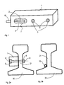
- FIG 1 shows a perspective view of the inventive Power cable termination.
- Power cable termination serves a rectangular or square metal profile, e.g. made of aluminium or steel, the length of which is preferably shorter than that Free space between two sleepers of a track.
- a Termination resistor 2 is provided at the terminating resistor 2 .
- a data cable 10 is connected at the terminating resistor 2 .
- the arranged in the recess 4 Terminating resistor 2 is preferably factory-made with a Potting compound 7 filled.
- the data cable 10 is in advance to be connected to the terminating resistor 2.
- the potting compound 7 should be chosen so that the elasticity in the expected Temperature range is maintained. This is particularly true note for temperatures in the range of -30 ° C ..- 40 ° C, as easily reached in Nordic countries in winter become.
- On the right side of the case 1 are two Drilled holes 3 formed as through holes, which for fastening the power cable termination according to the invention serve.
- a cylindrical countersunk hole 9 is provided.
- a strain relief provided to arise in particular during assembly Do not apply forces directly to the terminating resistor 2 or the connection of data cable 1 with the terminating resistor 2 to act (not shown in Fig. 1).
- Fig. 2a is the attachment of the invention Power cable termination shown. Before assembly is the one intended for fastening the power cable termination Sand the side of the web 21 of the rail 20, thus the best possible thermal conductivity between the Housing 1 and the rail 20 is formed.
- the assembly of the inventive Power cable termination is preferred symmetrical to the space between two sleepers one Track should be provided to avoid complications with the locking means, such as. Screws or clamps, for fastening to provoke the rails with the threshold.
- the precise assembly of the power cable termination symmetrical to the Free space between two thresholds can e.g. with a device as in SIGANL + DRAHT (91) 10/99 on the pages 24 and 25 is described, made particularly simple become.
- the assembly is done with two Allen screws 6, their Heads 8 "disappear" in the countersunk hole 9 of the housing. In order to dangers from the projecting are eliminated. As The counterpart is a nut 5. To secure against loosening the Screws can be measures known to the person skilled in the art, e.g. a split pin must be provided.
- FIG. 2b The position of the data cable on the rail base is shown in FIG. 2b a rail 20 shown.
- Power cable termination experiences the data cable a slight S-shaped bend to introduce it into the Housing 1.
- the arrangement of the data cable 10 as well as the power cable termination can both inside and outside the track be made.
- the cross section of the housing 1 can be of any type, however, one side is to be designed in such a flat manner that good thermal contact to the web 21 of the rail 20 arises.
Landscapes
- Engineering & Computer Science (AREA)
- Microelectronics & Electronic Packaging (AREA)
- Installation Of Indoor Wiring (AREA)
- Insulated Conductors (AREA)
- Communication Cables (AREA)
- Train Traffic Observation, Control, And Security (AREA)
Abstract
Description
- i)
- Dadurch dass die Befestigungsmittel aus wenigstens zwei Schrauben gebildet werden; ergibt sich eine leichte und doch sehr stabile Montierbarkeit an einer beliebigen Lage längs einer Schiene (Patentanspruch 2).
- ii)
- Dadurch dass die Schrauben als Inbusschrauben ausgebildet sind, deren Köpfe in einem Versenkloch des Gehäuses versenkt angeordnet sind; treten durch die Befestigung keine vorstehenden Teile auf und eliminieren jede Gefahr durch vorstehende Teile (Patentanspruch 3).
- iii)
- Dadurch dass das Gehäuse einen rechteckigen Querschnitt aufweist und dass einseitig eine ovalförmige Ausnehmung zur Aufnahme des Abschlusswiderstandes vorgesehen ist; ergibt sich eine leichte Herstellbarkeit des Gehäuses und ein zuverlässiger Schutz des in der Ausnehmung befindlichen Widerstandes gegen äussere mechanischer Beschädigungen (Patentanspruch 4).
- iv)
- Dadurch dass der Abschlusswiderstand in der ovalförmigen Ausnehmung von einer Vergussmasse umgeben ist; ist die mechanische Beanspruchung zwischen Datenkabel und Abschlusswiderstand deutlich reduziert und eine gleichmässige Wärmeabfuhr an das umgebende Gehäuse ist sichergestellt (Patentanspruch 5).
- v)
- Dadurch dass das Gehäuse von länglicher Gestalt ist und im Querschnitt rechteckförmig oder quadratisch ist; wird die Herstellbarkeit solcher Gehäuse durch die Verwendung von Profilmaterial erheblich vereinfacht (Patentanspruch 7)
- Figur 1
- eine perspektivische Ansicht des erfindungsgemässen Leistungskabelabschlusses;
- Figur 2a
- Schnitt durch einen an einer Schiene befestigten erfindungsgemässen Leistungskabelabschlusses im Bereich eines Befestigungsmittels.
- Figur 2b
- Schnitt durch eine Schiene, an der ein Datenkabel montiert ist.
- 1
- Gehäuse
- 2
- Abschlusswiderstand
- 3
- Bohrung für Schraube
- 4
- Ausnehmung
- 5
- Mutter
- 6
- Schraube
- 7
- Vergussmasse
- 8
- Inbusschraubenkopf
- 9
- Versenkloch
- 10
- Datenkabel
- 20
- Schiene
- 21
- Steg
Claims (7)
- Leistungskabelabschluss für ein längs einer Eisenbahnstrecke angeordnetes an einer Schiene (20) befestigtes Datenkabel (10), der aus einem einen Abschlusswiderstand (2) enthaltenden Gehäuse (1) gebildet wird,
dadurch gekennzeichnet, dass
das Gehäuse (1) flächig an die Schiene mit Befestigungsmitteln (5, 6) fest montiert ist. - Leistungskabelabschluss nach Anspruch 1,
dadurch gekennzeichnet, dass
die Befestigungsmittel (5, 6) aus wenigstens zwei Schrauben (6) gebildet werden. - Leistungskabelabschluss nach Anspruch 2,
dadurch gekennzeichnet, dass
die Schrauben (6) als Inbusschrauben ausgebildet sind, deren Köpfe (8) in einem Versenkloch (9) des Gehäuses (1) versenkt angeordnet sind. - Leistungskabelabschluss nach einem der Ansprüche 1 bis 3,
dadurch gekennzeichnet, dass
das Gehäuse (1) einen rechteckigen Querschnitt aufweist und dass einseitig eine ovalförmige Ausnehmung (4) zur Aufnahme des Abschlusswiderstandes (2) vorgesehen ist. - Leistungskabelabschluss nach Anspruch 4,
dadurch gekennzeichnet, dass
der Abschlusswiderstand (2) in der ovalförmigen Ausnehmung (4) mit von einer Vergussmasse (7) umgeben ist. - Leistungskabelabschluss nach einem der Ansprüche 1 bis 5,
dadurch gekennzeichnet, dass
das Gehäuse (1) an einer Einführung für das Datenkabel (10) eine Zugentlastung aufweist. - Leistungskabelabschluss nach einem der Ansprüche 1 bis 6,
dadurch gekennzeichnet, dass
das Gehäuse (1) von länglicher Gestalt ist und im Querschnitt rechteckförmig oder quadratisch ist.
Priority Applications (5)
| Application Number | Priority Date | Filing Date | Title |
|---|---|---|---|
| DE50108775T DE50108775D1 (de) | 2001-05-17 | 2001-05-17 | Leistungskabelabschluss für ein Datenkabel längs einer Eisenbahnstrecke |
| DK01112113T DK1258890T3 (da) | 2001-05-17 | 2001-05-17 | Effektkabelterminering af et datakabel langs med en jernbanestrækning |
| EP01112113A EP1258890B1 (de) | 2001-05-17 | 2001-05-17 | Leistungskabelabschluss für ein Datenkabel längs einer Eisenbahnstrecke |
| ES01112113T ES2253301T3 (es) | 2001-05-17 | 2001-05-17 | Terminacion de un cable de potencia para un cable de datos dispuesto a lo largo de una via de ferrocarril. |
| AT01112113T ATE316685T1 (de) | 2001-05-17 | 2001-05-17 | Leistungskabelabschluss für ein datenkabel längs einer eisenbahnstrecke |
Applications Claiming Priority (1)
| Application Number | Priority Date | Filing Date | Title |
|---|---|---|---|
| EP01112113A EP1258890B1 (de) | 2001-05-17 | 2001-05-17 | Leistungskabelabschluss für ein Datenkabel längs einer Eisenbahnstrecke |
Publications (2)
| Publication Number | Publication Date |
|---|---|
| EP1258890A1 true EP1258890A1 (de) | 2002-11-20 |
| EP1258890B1 EP1258890B1 (de) | 2006-01-25 |
Family
ID=8177458
Family Applications (1)
| Application Number | Title | Priority Date | Filing Date |
|---|---|---|---|
| EP01112113A Expired - Lifetime EP1258890B1 (de) | 2001-05-17 | 2001-05-17 | Leistungskabelabschluss für ein Datenkabel längs einer Eisenbahnstrecke |
Country Status (5)
| Country | Link |
|---|---|
| EP (1) | EP1258890B1 (de) |
| AT (1) | ATE316685T1 (de) |
| DE (1) | DE50108775D1 (de) |
| DK (1) | DK1258890T3 (de) |
| ES (1) | ES2253301T3 (de) |
Citations (1)
| Publication number | Priority date | Publication date | Assignee | Title |
|---|---|---|---|---|
| US6147308A (en) * | 1998-03-23 | 2000-11-14 | Santagata; Daniel A. | Heating cable connector for railroad switch heating system |
-
2001
- 2001-05-17 DK DK01112113T patent/DK1258890T3/da active
- 2001-05-17 EP EP01112113A patent/EP1258890B1/de not_active Expired - Lifetime
- 2001-05-17 ES ES01112113T patent/ES2253301T3/es not_active Expired - Lifetime
- 2001-05-17 DE DE50108775T patent/DE50108775D1/de not_active Expired - Lifetime
- 2001-05-17 AT AT01112113T patent/ATE316685T1/de not_active IP Right Cessation
Patent Citations (1)
| Publication number | Priority date | Publication date | Assignee | Title |
|---|---|---|---|---|
| US6147308A (en) * | 1998-03-23 | 2000-11-14 | Santagata; Daniel A. | Heating cable connector for railroad switch heating system |
Non-Patent Citations (2)
| Title |
|---|
| BEYER J: "Neue Anschlusstechnik für elektrische Verbindungen an der Schiene", SIGNAL UND DRAHT, vol. 91, no. 10, 19 October 1999 (1999-10-19), pages 24 - 25, XP001035287 * |
| STAMM B ET AL: "EUROLOOP proposal from Siemens for ERTMS/ETCS", SIGNAL UND DRAHT, MAY 1998, TETZLAFF VERLAG, GERMANY, vol. 90, no. 5, pages 5 - 9, XP001035292, ISSN: 0037-4997 * |
Also Published As
| Publication number | Publication date |
|---|---|
| DK1258890T3 (da) | 2006-06-06 |
| ES2253301T3 (es) | 2006-06-01 |
| EP1258890B1 (de) | 2006-01-25 |
| ATE316685T1 (de) | 2006-02-15 |
| DE50108775D1 (de) | 2006-04-13 |
Similar Documents
| Publication | Publication Date | Title |
|---|---|---|
| EP0637099B1 (de) | Reihenklemmenanordnung mit Überspannungsschutzorganen | |
| DE10032842A1 (de) | Leiterplattenkühlsystem | |
| DE102006003576B4 (de) | Überspannungsableiter mit Käfig-Design | |
| DE102020103128A1 (de) | Steckverbinder zum Laden eines Elektrofahrzeugs | |
| DE2159087A1 (de) | Stromabnahmeleitung für ein auf dem Erdboden fahrendes Fahrzeug | |
| DE4008417C2 (de) | Vorrichtung zur Verbindung der elektrischen Anschlüsse von Kondensatoren | |
| WO2007085424A1 (de) | Stromleiter für eine elektrische einrichtung, insbesondere sammelschienenleiter für eine elektrische mittelspannungsanlage | |
| EP1258890B1 (de) | Leistungskabelabschluss für ein Datenkabel längs einer Eisenbahnstrecke | |
| EP0475417A2 (de) | Anordnung von Führungselementen für elektrische Leitungen im Fassadenbereich von Gebäuden | |
| DE3920686C2 (de) | Stromschienen-Leiterplatte | |
| DE2948631A1 (de) | Schutzeinrichtung fuer einen verbindungskopf von telefonleitungen | |
| DE19631995B4 (de) | System zum Verbinden einer Weicheisenstromschiene mit einem Stromleiter | |
| EP4075616A1 (de) | Leitungsanordnung, verbindungsanordnung und energieübertragungssystem | |
| DE202012012274U1 (de) | Temperaturmessanordnung | |
| DE3246878A1 (de) | Kompaktkabelabzweigklemme | |
| DE3526741A1 (de) | Isolierte abspann- oder haengeklemme | |
| DE4126831C2 (de) | Stromschienensystem für Stromrichter | |
| EP3920294B1 (de) | Energieversorgungseinheit für ein brennstoffzellensystem, brennstoffzellensystem | |
| DE602004007798T2 (de) | Streckentrennerisolator | |
| DE202010008274U1 (de) | Elektrische Verbindung zwischen zwei Busbars aus ebenen Leitern und einer zwischen den Leitern angeordneten Isolationsschicht | |
| DE102018124985B4 (de) | Temperiervorrichtung und System | |
| EP0896409A2 (de) | Abzweigmuffe für Energiekabel | |
| DE60107043T2 (de) | Gerät zur Kontrolle eines internen Fehlerlichtbogens für einen Anschlussmodul in einer gasisolierten Hochspannungsleitung | |
| DE2652981C3 (de) | Verteilerelement zur Befestigung von AnschluBleitungen in Wraptechnik | |
| DE102004049982A1 (de) | Profil, Halterung und System zur berührungslosen Energieübertragung |
Legal Events
| Date | Code | Title | Description |
|---|---|---|---|
| PUAI | Public reference made under article 153(3) epc to a published international application that has entered the european phase |
Free format text: ORIGINAL CODE: 0009012 |
|
| AK | Designated contracting states |
Kind code of ref document: A1 Designated state(s): AT BE CH CY DE DK ES FI FR GB GR IE IT LI LU MC NL PT SE TR |
|
| AX | Request for extension of the european patent |
Free format text: AL;LT;LV;MK;RO;SI |
|
| 17P | Request for examination filed |
Effective date: 20021216 |
|
| AKX | Designation fees paid |
Designated state(s): AT BE CH CY DE DK ES FI FR GB GR IE IT LI LU MC NL PT SE TR |
|
| GRAP | Despatch of communication of intention to grant a patent |
Free format text: ORIGINAL CODE: EPIDOSNIGR1 |
|
| GRAS | Grant fee paid |
Free format text: ORIGINAL CODE: EPIDOSNIGR3 |
|
| GRAA | (expected) grant |
Free format text: ORIGINAL CODE: 0009210 |
|
| AK | Designated contracting states |
Kind code of ref document: B1 Designated state(s): AT BE CH CY DE DK ES FI FR GB GR IE IT LI LU MC NL PT SE TR |
|
| REG | Reference to a national code |
Ref country code: GB Ref legal event code: FG4D Free format text: NOT ENGLISH |
|
| REG | Reference to a national code |
Ref country code: CH Ref legal event code: EP |
|
| REG | Reference to a national code |
Ref country code: IE Ref legal event code: FG4D Free format text: LANGUAGE OF EP DOCUMENT: GERMAN |
|
| GBT | Gb: translation of ep patent filed (gb section 77(6)(a)/1977) |
Effective date: 20060306 |
|
| REF | Corresponds to: |
Ref document number: 50108775 Country of ref document: DE Date of ref document: 20060413 Kind code of ref document: P |
|
| REG | Reference to a national code |
Ref country code: SE Ref legal event code: TRGR |
|
| REG | Reference to a national code |
Ref country code: GR Ref legal event code: EP Ref document number: 20060401037 Country of ref document: GR |
|
| REG | Reference to a national code |
Ref country code: ES Ref legal event code: FG2A Ref document number: 2253301 Country of ref document: ES Kind code of ref document: T3 |
|
| REG | Reference to a national code |
Ref country code: DK Ref legal event code: T3 |
|
| ET | Fr: translation filed | ||
| PLBE | No opposition filed within time limit |
Free format text: ORIGINAL CODE: 0009261 |
|
| STAA | Information on the status of an ep patent application or granted ep patent |
Free format text: STATUS: NO OPPOSITION FILED WITHIN TIME LIMIT |
|
| 26N | No opposition filed |
Effective date: 20061026 |
|
| PGFP | Annual fee paid to national office [announced via postgrant information from national office to epo] |
Ref country code: TR Payment date: 20080428 Year of fee payment: 8 |
|
| REG | Reference to a national code |
Ref country code: CH Ref legal event code: PCOW Free format text: SIEMENS SCHWEIZ AG;FREILAGERSTRASSE 40;8047 ZUERICH (CH) |
|
| PGFP | Annual fee paid to national office [announced via postgrant information from national office to epo] |
Ref country code: FI Payment date: 20100506 Year of fee payment: 10 Ref country code: DK Payment date: 20100506 Year of fee payment: 10 Ref country code: FR Payment date: 20100603 Year of fee payment: 10 Ref country code: IE Payment date: 20100527 Year of fee payment: 10 Ref country code: MC Payment date: 20100513 Year of fee payment: 10 Ref country code: LU Payment date: 20100510 Year of fee payment: 10 Ref country code: PT Payment date: 20100430 Year of fee payment: 10 |
|
| PGFP | Annual fee paid to national office [announced via postgrant information from national office to epo] |
Ref country code: IT Payment date: 20100526 Year of fee payment: 10 Ref country code: AT Payment date: 20100409 Year of fee payment: 10 Ref country code: NL Payment date: 20100528 Year of fee payment: 10 |
|
| PGFP | Annual fee paid to national office [announced via postgrant information from national office to epo] |
Ref country code: GB Payment date: 20100510 Year of fee payment: 10 Ref country code: SE Payment date: 20100506 Year of fee payment: 10 |
|
| PGFP | Annual fee paid to national office [announced via postgrant information from national office to epo] |
Ref country code: GR Payment date: 20100518 Year of fee payment: 10 Ref country code: CY Payment date: 20100513 Year of fee payment: 10 |
|
| REG | Reference to a national code |
Ref country code: PT Ref legal event code: MM4A Free format text: LAPSE DUE TO NON-PAYMENT OF FEES Effective date: 20111117 |
|
| REG | Reference to a national code |
Ref country code: NL Ref legal event code: V1 Effective date: 20111201 |
|
| PG25 | Lapsed in a contracting state [announced via postgrant information from national office to epo] |
Ref country code: MC Free format text: LAPSE BECAUSE OF NON-PAYMENT OF DUE FEES Effective date: 20110531 |
|
| REG | Reference to a national code |
Ref country code: DK Ref legal event code: EBP |
|
| REG | Reference to a national code |
Ref country code: SE Ref legal event code: EUG |
|
| GBPC | Gb: european patent ceased through non-payment of renewal fee |
Effective date: 20110517 |
|
| PG25 | Lapsed in a contracting state [announced via postgrant information from national office to epo] |
Ref country code: FI Free format text: LAPSE BECAUSE OF NON-PAYMENT OF DUE FEES Effective date: 20110517 Ref country code: PT Free format text: LAPSE BECAUSE OF NON-PAYMENT OF DUE FEES Effective date: 20111117 Ref country code: NL Free format text: LAPSE BECAUSE OF NON-PAYMENT OF DUE FEES Effective date: 20111201 |
|
| REG | Reference to a national code |
Ref country code: GR Ref legal event code: ML Ref document number: 20060401037 Country of ref document: GR Effective date: 20111202 |
|
| REG | Reference to a national code |
Ref country code: AT Ref legal event code: MM01 Ref document number: 316685 Country of ref document: AT Kind code of ref document: T Effective date: 20110517 |
|
| REG | Reference to a national code |
Ref country code: FR Ref legal event code: ST Effective date: 20120131 |
|
| PG25 | Lapsed in a contracting state [announced via postgrant information from national office to epo] |
Ref country code: AT Free format text: LAPSE BECAUSE OF NON-PAYMENT OF DUE FEES Effective date: 20110517 Ref country code: CY Free format text: LAPSE BECAUSE OF NON-PAYMENT OF DUE FEES Effective date: 20110517 Ref country code: GR Free format text: LAPSE BECAUSE OF NON-PAYMENT OF DUE FEES Effective date: 20111202 Ref country code: IT Free format text: LAPSE BECAUSE OF NON-PAYMENT OF DUE FEES Effective date: 20110517 |
|
| REG | Reference to a national code |
Ref country code: IE Ref legal event code: MM4A |
|
| PG25 | Lapsed in a contracting state [announced via postgrant information from national office to epo] |
Ref country code: FR Free format text: LAPSE BECAUSE OF NON-PAYMENT OF DUE FEES Effective date: 20110531 Ref country code: IE Free format text: LAPSE BECAUSE OF NON-PAYMENT OF DUE FEES Effective date: 20110517 |
|
| PG25 | Lapsed in a contracting state [announced via postgrant information from national office to epo] |
Ref country code: GB Free format text: LAPSE BECAUSE OF NON-PAYMENT OF DUE FEES Effective date: 20110517 Ref country code: DK Free format text: LAPSE BECAUSE OF NON-PAYMENT OF DUE FEES Effective date: 20110531 |
|
| PGFP | Annual fee paid to national office [announced via postgrant information from national office to epo] |
Ref country code: BE Payment date: 20120621 Year of fee payment: 12 |
|
| PGFP | Annual fee paid to national office [announced via postgrant information from national office to epo] |
Ref country code: ES Payment date: 20120621 Year of fee payment: 12 |
|
| PG25 | Lapsed in a contracting state [announced via postgrant information from national office to epo] |
Ref country code: TR Free format text: LAPSE BECAUSE OF NON-PAYMENT OF DUE FEES Effective date: 20090517 |
|
| PG25 | Lapsed in a contracting state [announced via postgrant information from national office to epo] |
Ref country code: SE Free format text: LAPSE BECAUSE OF NON-PAYMENT OF DUE FEES Effective date: 20110518 |
|
| PG25 | Lapsed in a contracting state [announced via postgrant information from national office to epo] |
Ref country code: LU Free format text: LAPSE BECAUSE OF NON-PAYMENT OF DUE FEES Effective date: 20110517 |
|
| PGFP | Annual fee paid to national office [announced via postgrant information from national office to epo] |
Ref country code: DE Payment date: 20130719 Year of fee payment: 13 |
|
| BERE | Be: lapsed |
Owner name: *SIEMENS SCHWEIZ A.G. Effective date: 20130531 |
|
| PG25 | Lapsed in a contracting state [announced via postgrant information from national office to epo] |
Ref country code: BE Free format text: LAPSE BECAUSE OF NON-PAYMENT OF DUE FEES Effective date: 20130531 |
|
| REG | Reference to a national code |
Ref country code: DE Ref legal event code: R119 Ref document number: 50108775 Country of ref document: DE |
|
| REG | Reference to a national code |
Ref country code: DE Ref legal event code: R119 Ref document number: 50108775 Country of ref document: DE Effective date: 20141202 |
|
| PG25 | Lapsed in a contracting state [announced via postgrant information from national office to epo] |
Ref country code: DE Free format text: LAPSE BECAUSE OF NON-PAYMENT OF DUE FEES Effective date: 20141202 |
|
| REG | Reference to a national code |
Ref country code: ES Ref legal event code: FD2A Effective date: 20150731 |
|
| PG25 | Lapsed in a contracting state [announced via postgrant information from national office to epo] |
Ref country code: ES Free format text: LAPSE BECAUSE OF NON-PAYMENT OF DUE FEES Effective date: 20140518 |
|
| PGFP | Annual fee paid to national office [announced via postgrant information from national office to epo] |
Ref country code: CH Payment date: 20150803 Year of fee payment: 15 |
|
| REG | Reference to a national code |
Ref country code: CH Ref legal event code: PL |
|
| PG25 | Lapsed in a contracting state [announced via postgrant information from national office to epo] |
Ref country code: CH Free format text: LAPSE BECAUSE OF NON-PAYMENT OF DUE FEES Effective date: 20160531 Ref country code: LI Free format text: LAPSE BECAUSE OF NON-PAYMENT OF DUE FEES Effective date: 20160531 |