EP1258283A1 - Device forming fuel gas for fuel cell and composite material for hydrogen separation - Google Patents
Device forming fuel gas for fuel cell and composite material for hydrogen separation Download PDFInfo
- Publication number
- EP1258283A1 EP1258283A1 EP00974892A EP00974892A EP1258283A1 EP 1258283 A1 EP1258283 A1 EP 1258283A1 EP 00974892 A EP00974892 A EP 00974892A EP 00974892 A EP00974892 A EP 00974892A EP 1258283 A1 EP1258283 A1 EP 1258283A1
- Authority
- EP
- European Patent Office
- Prior art keywords
- hydrogen
- hydrogen separation
- porous support
- support medium
- supported
- Prior art date
- Legal status (The legal status is an assumption and is not a legal conclusion. Google has not performed a legal analysis and makes no representation as to the accuracy of the status listed.)
- Granted
Links
Images

















Classifications
-
- B—PERFORMING OPERATIONS; TRANSPORTING
- B01—PHYSICAL OR CHEMICAL PROCESSES OR APPARATUS IN GENERAL
- B01D—SEPARATION
- B01D69/00—Semi-permeable membranes for separation processes or apparatus characterised by their form, structure or properties; Manufacturing processes specially adapted therefor
- B01D69/14—Dynamic membranes
- B01D69/141—Heterogeneous membranes, e.g. containing dispersed material; Mixed matrix membranes
- B01D69/145—Heterogeneous membranes, e.g. containing dispersed material; Mixed matrix membranes containing embedded catalysts
-
- B—PERFORMING OPERATIONS; TRANSPORTING
- B01—PHYSICAL OR CHEMICAL PROCESSES OR APPARATUS IN GENERAL
- B01D—SEPARATION
- B01D53/00—Separation of gases or vapours; Recovering vapours of volatile solvents from gases; Chemical or biological purification of waste gases, e.g. engine exhaust gases, smoke, fumes, flue gases, aerosols
- B01D53/22—Separation of gases or vapours; Recovering vapours of volatile solvents from gases; Chemical or biological purification of waste gases, e.g. engine exhaust gases, smoke, fumes, flue gases, aerosols by diffusion
- B01D53/228—Separation of gases or vapours; Recovering vapours of volatile solvents from gases; Chemical or biological purification of waste gases, e.g. engine exhaust gases, smoke, fumes, flue gases, aerosols by diffusion characterised by specific membranes
-
- B—PERFORMING OPERATIONS; TRANSPORTING
- B01—PHYSICAL OR CHEMICAL PROCESSES OR APPARATUS IN GENERAL
- B01D—SEPARATION
- B01D53/00—Separation of gases or vapours; Recovering vapours of volatile solvents from gases; Chemical or biological purification of waste gases, e.g. engine exhaust gases, smoke, fumes, flue gases, aerosols
- B01D53/34—Chemical or biological purification of waste gases
- B01D53/74—General processes for purification of waste gases; Apparatus or devices specially adapted therefor
- B01D53/86—Catalytic processes
- B01D53/864—Removing carbon monoxide or hydrocarbons
-
- B—PERFORMING OPERATIONS; TRANSPORTING
- B01—PHYSICAL OR CHEMICAL PROCESSES OR APPARATUS IN GENERAL
- B01D—SEPARATION
- B01D67/00—Processes specially adapted for manufacturing semi-permeable membranes for separation processes or apparatus
- B01D67/0039—Inorganic membrane manufacture
- B01D67/0069—Inorganic membrane manufacture by deposition from the liquid phase, e.g. electrochemical deposition
-
- B—PERFORMING OPERATIONS; TRANSPORTING
- B01—PHYSICAL OR CHEMICAL PROCESSES OR APPARATUS IN GENERAL
- B01D—SEPARATION
- B01D67/00—Processes specially adapted for manufacturing semi-permeable membranes for separation processes or apparatus
- B01D67/0039—Inorganic membrane manufacture
- B01D67/0072—Inorganic membrane manufacture by deposition from the gaseous phase, e.g. sputtering, CVD, PVD
-
- B—PERFORMING OPERATIONS; TRANSPORTING
- B01—PHYSICAL OR CHEMICAL PROCESSES OR APPARATUS IN GENERAL
- B01D—SEPARATION
- B01D69/00—Semi-permeable membranes for separation processes or apparatus characterised by their form, structure or properties; Manufacturing processes specially adapted therefor
- B01D69/10—Supported membranes; Membrane supports
- B01D69/108—Inorganic support material
-
- B—PERFORMING OPERATIONS; TRANSPORTING
- B01—PHYSICAL OR CHEMICAL PROCESSES OR APPARATUS IN GENERAL
- B01D—SEPARATION
- B01D71/00—Semi-permeable membranes for separation processes or apparatus characterised by the material; Manufacturing processes specially adapted therefor
- B01D71/02—Inorganic material
- B01D71/0215—Silicon carbide; Silicon nitride; Silicon oxycarbide
-
- B—PERFORMING OPERATIONS; TRANSPORTING
- B01—PHYSICAL OR CHEMICAL PROCESSES OR APPARATUS IN GENERAL
- B01D—SEPARATION
- B01D71/00—Semi-permeable membranes for separation processes or apparatus characterised by the material; Manufacturing processes specially adapted therefor
- B01D71/02—Inorganic material
- B01D71/022—Metals
- B01D71/0223—Group 8, 9 or 10 metals
- B01D71/02231—Palladium
-
- B—PERFORMING OPERATIONS; TRANSPORTING
- B01—PHYSICAL OR CHEMICAL PROCESSES OR APPARATUS IN GENERAL
- B01J—CHEMICAL OR PHYSICAL PROCESSES, e.g. CATALYSIS OR COLLOID CHEMISTRY; THEIR RELEVANT APPARATUS
- B01J12/00—Chemical processes in general for reacting gaseous media with gaseous media; Apparatus specially adapted therefor
- B01J12/007—Chemical processes in general for reacting gaseous media with gaseous media; Apparatus specially adapted therefor in the presence of catalytically active bodies, e.g. porous plates
-
- B—PERFORMING OPERATIONS; TRANSPORTING
- B01—PHYSICAL OR CHEMICAL PROCESSES OR APPARATUS IN GENERAL
- B01J—CHEMICAL OR PHYSICAL PROCESSES, e.g. CATALYSIS OR COLLOID CHEMISTRY; THEIR RELEVANT APPARATUS
- B01J19/00—Chemical, physical or physico-chemical processes in general; Their relevant apparatus
- B01J19/24—Stationary reactors without moving elements inside
- B01J19/2415—Tubular reactors
- B01J19/2425—Tubular reactors in parallel
-
- B—PERFORMING OPERATIONS; TRANSPORTING
- B01—PHYSICAL OR CHEMICAL PROCESSES OR APPARATUS IN GENERAL
- B01J—CHEMICAL OR PHYSICAL PROCESSES, e.g. CATALYSIS OR COLLOID CHEMISTRY; THEIR RELEVANT APPARATUS
- B01J19/00—Chemical, physical or physico-chemical processes in general; Their relevant apparatus
- B01J19/24—Stationary reactors without moving elements inside
- B01J19/2475—Membrane reactors
-
- B—PERFORMING OPERATIONS; TRANSPORTING
- B01—PHYSICAL OR CHEMICAL PROCESSES OR APPARATUS IN GENERAL
- B01J—CHEMICAL OR PHYSICAL PROCESSES, e.g. CATALYSIS OR COLLOID CHEMISTRY; THEIR RELEVANT APPARATUS
- B01J19/00—Chemical, physical or physico-chemical processes in general; Their relevant apparatus
- B01J19/24—Stationary reactors without moving elements inside
- B01J19/248—Reactors comprising multiple separated flow channels
- B01J19/2485—Monolithic reactors
-
- B—PERFORMING OPERATIONS; TRANSPORTING
- B01—PHYSICAL OR CHEMICAL PROCESSES OR APPARATUS IN GENERAL
- B01J—CHEMICAL OR PHYSICAL PROCESSES, e.g. CATALYSIS OR COLLOID CHEMISTRY; THEIR RELEVANT APPARATUS
- B01J8/00—Chemical or physical processes in general, conducted in the presence of fluids and solid particles; Apparatus for such processes
- B01J8/008—Details of the reactor or of the particulate material; Processes to increase or to retard the rate of reaction
- B01J8/009—Membranes, e.g. feeding or removing reactants or products to or from the catalyst bed through a membrane
-
- C—CHEMISTRY; METALLURGY
- C01—INORGANIC CHEMISTRY
- C01B—NON-METALLIC ELEMENTS; COMPOUNDS THEREOF; METALLOIDS OR COMPOUNDS THEREOF NOT COVERED BY SUBCLASS C01C
- C01B3/00—Hydrogen; Gaseous mixtures containing hydrogen; Separation of hydrogen from mixtures containing it; Purification of hydrogen; Reversible storage of hydrogen
- C01B3/02—Production of hydrogen; Production of gaseous mixtures containing hydrogen
- C01B3/32—Production of hydrogen; Production of gaseous mixtures containing hydrogen by reaction of gaseous or liquid organic compounds with gasifying agents, e.g. water, carbon dioxide or air
- C01B3/34—Production of hydrogen; Production of gaseous mixtures containing hydrogen by reaction of gaseous or liquid organic compounds with gasifying agents, e.g. water, carbon dioxide or air by reaction of hydrocarbons with gasifying agents
- C01B3/38—Production of hydrogen; Production of gaseous mixtures containing hydrogen by reaction of gaseous or liquid organic compounds with gasifying agents, e.g. water, carbon dioxide or air by reaction of hydrocarbons with gasifying agents using catalysts
-
- C—CHEMISTRY; METALLURGY
- C01—INORGANIC CHEMISTRY
- C01B—NON-METALLIC ELEMENTS; COMPOUNDS THEREOF; METALLOIDS OR COMPOUNDS THEREOF NOT COVERED BY SUBCLASS C01C
- C01B3/00—Hydrogen; Gaseous mixtures containing hydrogen; Separation of hydrogen from mixtures containing it; Purification of hydrogen; Reversible storage of hydrogen
- C01B3/02—Production of hydrogen; Production of gaseous mixtures containing hydrogen
- C01B3/32—Production of hydrogen; Production of gaseous mixtures containing hydrogen by reaction of gaseous or liquid organic compounds with gasifying agents, e.g. water, carbon dioxide or air
- C01B3/34—Production of hydrogen; Production of gaseous mixtures containing hydrogen by reaction of gaseous or liquid organic compounds with gasifying agents, e.g. water, carbon dioxide or air by reaction of hydrocarbons with gasifying agents
- C01B3/38—Production of hydrogen; Production of gaseous mixtures containing hydrogen by reaction of gaseous or liquid organic compounds with gasifying agents, e.g. water, carbon dioxide or air by reaction of hydrocarbons with gasifying agents using catalysts
- C01B3/40—Production of hydrogen; Production of gaseous mixtures containing hydrogen by reaction of gaseous or liquid organic compounds with gasifying agents, e.g. water, carbon dioxide or air by reaction of hydrocarbons with gasifying agents using catalysts characterised by the catalyst
-
- C—CHEMISTRY; METALLURGY
- C01—INORGANIC CHEMISTRY
- C01B—NON-METALLIC ELEMENTS; COMPOUNDS THEREOF; METALLOIDS OR COMPOUNDS THEREOF NOT COVERED BY SUBCLASS C01C
- C01B3/00—Hydrogen; Gaseous mixtures containing hydrogen; Separation of hydrogen from mixtures containing it; Purification of hydrogen; Reversible storage of hydrogen
- C01B3/50—Separation of hydrogen or hydrogen-containing gases from gaseous mixtures, e.g. purification
- C01B3/501—Separation of hydrogen or hydrogen-containing gases from gaseous mixtures, e.g. purification by diffusion
- C01B3/503—Separation of hydrogen or hydrogen-containing gases from gaseous mixtures, e.g. purification by diffusion characterised by membranes
-
- C—CHEMISTRY; METALLURGY
- C01—INORGANIC CHEMISTRY
- C01B—NON-METALLIC ELEMENTS; COMPOUNDS THEREOF; METALLOIDS OR COMPOUNDS THEREOF NOT COVERED BY SUBCLASS C01C
- C01B3/00—Hydrogen; Gaseous mixtures containing hydrogen; Separation of hydrogen from mixtures containing it; Purification of hydrogen; Reversible storage of hydrogen
- C01B3/50—Separation of hydrogen or hydrogen-containing gases from gaseous mixtures, e.g. purification
- C01B3/501—Separation of hydrogen or hydrogen-containing gases from gaseous mixtures, e.g. purification by diffusion
- C01B3/503—Separation of hydrogen or hydrogen-containing gases from gaseous mixtures, e.g. purification by diffusion characterised by membranes
- C01B3/505—Membranes containing palladium
-
- H—ELECTRICITY
- H01—ELECTRIC ELEMENTS
- H01M—PROCESSES OR MEANS, e.g. BATTERIES, FOR THE DIRECT CONVERSION OF CHEMICAL ENERGY INTO ELECTRICAL ENERGY
- H01M4/00—Electrodes
- H01M4/86—Inert electrodes with catalytic activity, e.g. for fuel cells
- H01M4/94—Non-porous diffusion electrodes, e.g. palladium membranes, ion exchange membranes
-
- H—ELECTRICITY
- H01—ELECTRIC ELEMENTS
- H01M—PROCESSES OR MEANS, e.g. BATTERIES, FOR THE DIRECT CONVERSION OF CHEMICAL ENERGY INTO ELECTRICAL ENERGY
- H01M8/00—Fuel cells; Manufacture thereof
- H01M8/06—Combination of fuel cells with means for production of reactants or for treatment of residues
- H01M8/0606—Combination of fuel cells with means for production of reactants or for treatment of residues with means for production of gaseous reactants
- H01M8/0612—Combination of fuel cells with means for production of reactants or for treatment of residues with means for production of gaseous reactants from carbon-containing material
-
- H—ELECTRICITY
- H01—ELECTRIC ELEMENTS
- H01M—PROCESSES OR MEANS, e.g. BATTERIES, FOR THE DIRECT CONVERSION OF CHEMICAL ENERGY INTO ELECTRICAL ENERGY
- H01M8/00—Fuel cells; Manufacture thereof
- H01M8/06—Combination of fuel cells with means for production of reactants or for treatment of residues
- H01M8/0662—Treatment of gaseous reactants or gaseous residues, e.g. cleaning
-
- B—PERFORMING OPERATIONS; TRANSPORTING
- B01—PHYSICAL OR CHEMICAL PROCESSES OR APPARATUS IN GENERAL
- B01D—SEPARATION
- B01D2325/00—Details relating to properties of membranes
- B01D2325/06—Surface irregularities
-
- B—PERFORMING OPERATIONS; TRANSPORTING
- B01—PHYSICAL OR CHEMICAL PROCESSES OR APPARATUS IN GENERAL
- B01D—SEPARATION
- B01D2325/00—Details relating to properties of membranes
- B01D2325/10—Catalysts being present on the surface of the membrane or in the pores
-
- B—PERFORMING OPERATIONS; TRANSPORTING
- B01—PHYSICAL OR CHEMICAL PROCESSES OR APPARATUS IN GENERAL
- B01J—CHEMICAL OR PHYSICAL PROCESSES, e.g. CATALYSIS OR COLLOID CHEMISTRY; THEIR RELEVANT APPARATUS
- B01J2208/00—Processes carried out in the presence of solid particles; Reactors therefor
- B01J2208/00796—Details of the reactor or of the particulate material
- B01J2208/00823—Mixing elements
- B01J2208/00831—Stationary elements
- B01J2208/00849—Stationary elements outside the bed, e.g. baffles
-
- B—PERFORMING OPERATIONS; TRANSPORTING
- B01—PHYSICAL OR CHEMICAL PROCESSES OR APPARATUS IN GENERAL
- B01J—CHEMICAL OR PHYSICAL PROCESSES, e.g. CATALYSIS OR COLLOID CHEMISTRY; THEIR RELEVANT APPARATUS
- B01J2219/00—Chemical, physical or physico-chemical processes in general; Their relevant apparatus
- B01J2219/00049—Controlling or regulating processes
- B01J2219/00051—Controlling the temperature
- B01J2219/00132—Controlling the temperature using electric heating or cooling elements
- B01J2219/00137—Peltier cooling elements
-
- B—PERFORMING OPERATIONS; TRANSPORTING
- B01—PHYSICAL OR CHEMICAL PROCESSES OR APPARATUS IN GENERAL
- B01J—CHEMICAL OR PHYSICAL PROCESSES, e.g. CATALYSIS OR COLLOID CHEMISTRY; THEIR RELEVANT APPARATUS
- B01J2219/00—Chemical, physical or physico-chemical processes in general; Their relevant apparatus
- B01J2219/19—Details relating to the geometry of the reactor
- B01J2219/194—Details relating to the geometry of the reactor round
- B01J2219/1941—Details relating to the geometry of the reactor round circular or disk-shaped
- B01J2219/1944—Details relating to the geometry of the reactor round circular or disk-shaped spiral
-
- B—PERFORMING OPERATIONS; TRANSPORTING
- B01—PHYSICAL OR CHEMICAL PROCESSES OR APPARATUS IN GENERAL
- B01J—CHEMICAL OR PHYSICAL PROCESSES, e.g. CATALYSIS OR COLLOID CHEMISTRY; THEIR RELEVANT APPARATUS
- B01J2219/00—Chemical, physical or physico-chemical processes in general; Their relevant apparatus
- B01J2219/19—Details relating to the geometry of the reactor
- B01J2219/194—Details relating to the geometry of the reactor round
- B01J2219/1941—Details relating to the geometry of the reactor round circular or disk-shaped
- B01J2219/1945—Details relating to the geometry of the reactor round circular or disk-shaped toroidal
-
- C—CHEMISTRY; METALLURGY
- C01—INORGANIC CHEMISTRY
- C01B—NON-METALLIC ELEMENTS; COMPOUNDS THEREOF; METALLOIDS OR COMPOUNDS THEREOF NOT COVERED BY SUBCLASS C01C
- C01B2203/00—Integrated processes for the production of hydrogen or synthesis gas
- C01B2203/02—Processes for making hydrogen or synthesis gas
- C01B2203/0205—Processes for making hydrogen or synthesis gas containing a reforming step
- C01B2203/0227—Processes for making hydrogen or synthesis gas containing a reforming step containing a catalytic reforming step
- C01B2203/0233—Processes for making hydrogen or synthesis gas containing a reforming step containing a catalytic reforming step the reforming step being a steam reforming step
-
- C—CHEMISTRY; METALLURGY
- C01—INORGANIC CHEMISTRY
- C01B—NON-METALLIC ELEMENTS; COMPOUNDS THEREOF; METALLOIDS OR COMPOUNDS THEREOF NOT COVERED BY SUBCLASS C01C
- C01B2203/00—Integrated processes for the production of hydrogen or synthesis gas
- C01B2203/02—Processes for making hydrogen or synthesis gas
- C01B2203/0283—Processes for making hydrogen or synthesis gas containing a CO-shift step, i.e. a water gas shift step
-
- C—CHEMISTRY; METALLURGY
- C01—INORGANIC CHEMISTRY
- C01B—NON-METALLIC ELEMENTS; COMPOUNDS THEREOF; METALLOIDS OR COMPOUNDS THEREOF NOT COVERED BY SUBCLASS C01C
- C01B2203/00—Integrated processes for the production of hydrogen or synthesis gas
- C01B2203/04—Integrated processes for the production of hydrogen or synthesis gas containing a purification step for the hydrogen or the synthesis gas
- C01B2203/0405—Purification by membrane separation
- C01B2203/041—In-situ membrane purification during hydrogen production
-
- C—CHEMISTRY; METALLURGY
- C01—INORGANIC CHEMISTRY
- C01B—NON-METALLIC ELEMENTS; COMPOUNDS THEREOF; METALLOIDS OR COMPOUNDS THEREOF NOT COVERED BY SUBCLASS C01C
- C01B2203/00—Integrated processes for the production of hydrogen or synthesis gas
- C01B2203/04—Integrated processes for the production of hydrogen or synthesis gas containing a purification step for the hydrogen or the synthesis gas
- C01B2203/0435—Catalytic purification
- C01B2203/044—Selective oxidation of carbon monoxide
-
- C—CHEMISTRY; METALLURGY
- C01—INORGANIC CHEMISTRY
- C01B—NON-METALLIC ELEMENTS; COMPOUNDS THEREOF; METALLOIDS OR COMPOUNDS THEREOF NOT COVERED BY SUBCLASS C01C
- C01B2203/00—Integrated processes for the production of hydrogen or synthesis gas
- C01B2203/04—Integrated processes for the production of hydrogen or synthesis gas containing a purification step for the hydrogen or the synthesis gas
- C01B2203/0465—Composition of the impurity
- C01B2203/047—Composition of the impurity the impurity being carbon monoxide
-
- C—CHEMISTRY; METALLURGY
- C01—INORGANIC CHEMISTRY
- C01B—NON-METALLIC ELEMENTS; COMPOUNDS THEREOF; METALLOIDS OR COMPOUNDS THEREOF NOT COVERED BY SUBCLASS C01C
- C01B2203/00—Integrated processes for the production of hydrogen or synthesis gas
- C01B2203/04—Integrated processes for the production of hydrogen or synthesis gas containing a purification step for the hydrogen or the synthesis gas
- C01B2203/0465—Composition of the impurity
- C01B2203/0495—Composition of the impurity the impurity being water
-
- C—CHEMISTRY; METALLURGY
- C01—INORGANIC CHEMISTRY
- C01B—NON-METALLIC ELEMENTS; COMPOUNDS THEREOF; METALLOIDS OR COMPOUNDS THEREOF NOT COVERED BY SUBCLASS C01C
- C01B2203/00—Integrated processes for the production of hydrogen or synthesis gas
- C01B2203/06—Integration with other chemical processes
- C01B2203/066—Integration with other chemical processes with fuel cells
-
- C—CHEMISTRY; METALLURGY
- C01—INORGANIC CHEMISTRY
- C01B—NON-METALLIC ELEMENTS; COMPOUNDS THEREOF; METALLOIDS OR COMPOUNDS THEREOF NOT COVERED BY SUBCLASS C01C
- C01B2203/00—Integrated processes for the production of hydrogen or synthesis gas
- C01B2203/08—Methods of heating or cooling
- C01B2203/0872—Methods of cooling
- C01B2203/0883—Methods of cooling by indirect heat exchange
-
- C—CHEMISTRY; METALLURGY
- C01—INORGANIC CHEMISTRY
- C01B—NON-METALLIC ELEMENTS; COMPOUNDS THEREOF; METALLOIDS OR COMPOUNDS THEREOF NOT COVERED BY SUBCLASS C01C
- C01B2203/00—Integrated processes for the production of hydrogen or synthesis gas
- C01B2203/08—Methods of heating or cooling
- C01B2203/0872—Methods of cooling
- C01B2203/0888—Methods of cooling by evaporation of a fluid
- C01B2203/0894—Generation of steam
-
- C—CHEMISTRY; METALLURGY
- C01—INORGANIC CHEMISTRY
- C01B—NON-METALLIC ELEMENTS; COMPOUNDS THEREOF; METALLOIDS OR COMPOUNDS THEREOF NOT COVERED BY SUBCLASS C01C
- C01B2203/00—Integrated processes for the production of hydrogen or synthesis gas
- C01B2203/10—Catalysts for performing the hydrogen forming reactions
- C01B2203/1005—Arrangement or shape of catalyst
- C01B2203/1011—Packed bed of catalytic structures, e.g. particles, packing elements
-
- C—CHEMISTRY; METALLURGY
- C01—INORGANIC CHEMISTRY
- C01B—NON-METALLIC ELEMENTS; COMPOUNDS THEREOF; METALLOIDS OR COMPOUNDS THEREOF NOT COVERED BY SUBCLASS C01C
- C01B2203/00—Integrated processes for the production of hydrogen or synthesis gas
- C01B2203/10—Catalysts for performing the hydrogen forming reactions
- C01B2203/1005—Arrangement or shape of catalyst
- C01B2203/1023—Catalysts in the form of a monolith or honeycomb
-
- C—CHEMISTRY; METALLURGY
- C01—INORGANIC CHEMISTRY
- C01B—NON-METALLIC ELEMENTS; COMPOUNDS THEREOF; METALLOIDS OR COMPOUNDS THEREOF NOT COVERED BY SUBCLASS C01C
- C01B2203/00—Integrated processes for the production of hydrogen or synthesis gas
- C01B2203/10—Catalysts for performing the hydrogen forming reactions
- C01B2203/1041—Composition of the catalyst
- C01B2203/1047—Group VIII metal catalysts
- C01B2203/1052—Nickel or cobalt catalysts
-
- C—CHEMISTRY; METALLURGY
- C01—INORGANIC CHEMISTRY
- C01B—NON-METALLIC ELEMENTS; COMPOUNDS THEREOF; METALLOIDS OR COMPOUNDS THEREOF NOT COVERED BY SUBCLASS C01C
- C01B2203/00—Integrated processes for the production of hydrogen or synthesis gas
- C01B2203/10—Catalysts for performing the hydrogen forming reactions
- C01B2203/1041—Composition of the catalyst
- C01B2203/1047—Group VIII metal catalysts
- C01B2203/1052—Nickel or cobalt catalysts
- C01B2203/1058—Nickel catalysts
-
- C—CHEMISTRY; METALLURGY
- C01—INORGANIC CHEMISTRY
- C01B—NON-METALLIC ELEMENTS; COMPOUNDS THEREOF; METALLOIDS OR COMPOUNDS THEREOF NOT COVERED BY SUBCLASS C01C
- C01B2203/00—Integrated processes for the production of hydrogen or synthesis gas
- C01B2203/10—Catalysts for performing the hydrogen forming reactions
- C01B2203/1041—Composition of the catalyst
- C01B2203/1047—Group VIII metal catalysts
- C01B2203/1064—Platinum group metal catalysts
-
- C—CHEMISTRY; METALLURGY
- C01—INORGANIC CHEMISTRY
- C01B—NON-METALLIC ELEMENTS; COMPOUNDS THEREOF; METALLOIDS OR COMPOUNDS THEREOF NOT COVERED BY SUBCLASS C01C
- C01B2203/00—Integrated processes for the production of hydrogen or synthesis gas
- C01B2203/10—Catalysts for performing the hydrogen forming reactions
- C01B2203/1041—Composition of the catalyst
- C01B2203/1076—Copper or zinc-based catalysts
-
- C—CHEMISTRY; METALLURGY
- C01—INORGANIC CHEMISTRY
- C01B—NON-METALLIC ELEMENTS; COMPOUNDS THEREOF; METALLOIDS OR COMPOUNDS THEREOF NOT COVERED BY SUBCLASS C01C
- C01B2203/00—Integrated processes for the production of hydrogen or synthesis gas
- C01B2203/10—Catalysts for performing the hydrogen forming reactions
- C01B2203/1041—Composition of the catalyst
- C01B2203/1082—Composition of support materials
-
- C—CHEMISTRY; METALLURGY
- C01—INORGANIC CHEMISTRY
- C01B—NON-METALLIC ELEMENTS; COMPOUNDS THEREOF; METALLOIDS OR COMPOUNDS THEREOF NOT COVERED BY SUBCLASS C01C
- C01B2203/00—Integrated processes for the production of hydrogen or synthesis gas
- C01B2203/12—Feeding the process for making hydrogen or synthesis gas
- C01B2203/1205—Composition of the feed
- C01B2203/1211—Organic compounds or organic mixtures used in the process for making hydrogen or synthesis gas
- C01B2203/1217—Alcohols
- C01B2203/1223—Methanol
-
- C—CHEMISTRY; METALLURGY
- C01—INORGANIC CHEMISTRY
- C01B—NON-METALLIC ELEMENTS; COMPOUNDS THEREOF; METALLOIDS OR COMPOUNDS THEREOF NOT COVERED BY SUBCLASS C01C
- C01B2203/00—Integrated processes for the production of hydrogen or synthesis gas
- C01B2203/12—Feeding the process for making hydrogen or synthesis gas
- C01B2203/1205—Composition of the feed
- C01B2203/1211—Organic compounds or organic mixtures used in the process for making hydrogen or synthesis gas
- C01B2203/1235—Hydrocarbons
- C01B2203/1241—Natural gas or methane
-
- C—CHEMISTRY; METALLURGY
- C01—INORGANIC CHEMISTRY
- C01B—NON-METALLIC ELEMENTS; COMPOUNDS THEREOF; METALLOIDS OR COMPOUNDS THEREOF NOT COVERED BY SUBCLASS C01C
- C01B2203/00—Integrated processes for the production of hydrogen or synthesis gas
- C01B2203/12—Feeding the process for making hydrogen or synthesis gas
- C01B2203/1276—Mixing of different feed components
-
- C—CHEMISTRY; METALLURGY
- C01—INORGANIC CHEMISTRY
- C01B—NON-METALLIC ELEMENTS; COMPOUNDS THEREOF; METALLOIDS OR COMPOUNDS THEREOF NOT COVERED BY SUBCLASS C01C
- C01B2203/00—Integrated processes for the production of hydrogen or synthesis gas
- C01B2203/12—Feeding the process for making hydrogen or synthesis gas
- C01B2203/1288—Evaporation of one or more of the different feed components
-
- C—CHEMISTRY; METALLURGY
- C01—INORGANIC CHEMISTRY
- C01B—NON-METALLIC ELEMENTS; COMPOUNDS THEREOF; METALLOIDS OR COMPOUNDS THEREOF NOT COVERED BY SUBCLASS C01C
- C01B2203/00—Integrated processes for the production of hydrogen or synthesis gas
- C01B2203/14—Details of the flowsheet
- C01B2203/146—At least two purification steps in series
-
- C—CHEMISTRY; METALLURGY
- C01—INORGANIC CHEMISTRY
- C01B—NON-METALLIC ELEMENTS; COMPOUNDS THEREOF; METALLOIDS OR COMPOUNDS THEREOF NOT COVERED BY SUBCLASS C01C
- C01B2203/00—Integrated processes for the production of hydrogen or synthesis gas
- C01B2203/80—Aspect of integrated processes for the production of hydrogen or synthesis gas not covered by groups C01B2203/02 - C01B2203/1695
-
- C—CHEMISTRY; METALLURGY
- C01—INORGANIC CHEMISTRY
- C01B—NON-METALLIC ELEMENTS; COMPOUNDS THEREOF; METALLOIDS OR COMPOUNDS THEREOF NOT COVERED BY SUBCLASS C01C
- C01B2203/00—Integrated processes for the production of hydrogen or synthesis gas
- C01B2203/80—Aspect of integrated processes for the production of hydrogen or synthesis gas not covered by groups C01B2203/02 - C01B2203/1695
- C01B2203/82—Several process steps of C01B2203/02 - C01B2203/08 integrated into a single apparatus
-
- Y—GENERAL TAGGING OF NEW TECHNOLOGICAL DEVELOPMENTS; GENERAL TAGGING OF CROSS-SECTIONAL TECHNOLOGIES SPANNING OVER SEVERAL SECTIONS OF THE IPC; TECHNICAL SUBJECTS COVERED BY FORMER USPC CROSS-REFERENCE ART COLLECTIONS [XRACs] AND DIGESTS
- Y02—TECHNOLOGIES OR APPLICATIONS FOR MITIGATION OR ADAPTATION AGAINST CLIMATE CHANGE
- Y02E—REDUCTION OF GREENHOUSE GAS [GHG] EMISSIONS, RELATED TO ENERGY GENERATION, TRANSMISSION OR DISTRIBUTION
- Y02E60/00—Enabling technologies; Technologies with a potential or indirect contribution to GHG emissions mitigation
- Y02E60/30—Hydrogen technology
- Y02E60/50—Fuel cells
-
- Y—GENERAL TAGGING OF NEW TECHNOLOGICAL DEVELOPMENTS; GENERAL TAGGING OF CROSS-SECTIONAL TECHNOLOGIES SPANNING OVER SEVERAL SECTIONS OF THE IPC; TECHNICAL SUBJECTS COVERED BY FORMER USPC CROSS-REFERENCE ART COLLECTIONS [XRACs] AND DIGESTS
- Y02—TECHNOLOGIES OR APPLICATIONS FOR MITIGATION OR ADAPTATION AGAINST CLIMATE CHANGE
- Y02P—CLIMATE CHANGE MITIGATION TECHNOLOGIES IN THE PRODUCTION OR PROCESSING OF GOODS
- Y02P20/00—Technologies relating to chemical industry
- Y02P20/141—Feedstock
-
- Y—GENERAL TAGGING OF NEW TECHNOLOGICAL DEVELOPMENTS; GENERAL TAGGING OF CROSS-SECTIONAL TECHNOLOGIES SPANNING OVER SEVERAL SECTIONS OF THE IPC; TECHNICAL SUBJECTS COVERED BY FORMER USPC CROSS-REFERENCE ART COLLECTIONS [XRACs] AND DIGESTS
- Y02—TECHNOLOGIES OR APPLICATIONS FOR MITIGATION OR ADAPTATION AGAINST CLIMATE CHANGE
- Y02P—CLIMATE CHANGE MITIGATION TECHNOLOGIES IN THE PRODUCTION OR PROCESSING OF GOODS
- Y02P20/00—Technologies relating to chemical industry
- Y02P20/50—Improvements relating to the production of bulk chemicals
- Y02P20/52—Improvements relating to the production of bulk chemicals using catalysts, e.g. selective catalysts
-
- Y—GENERAL TAGGING OF NEW TECHNOLOGICAL DEVELOPMENTS; GENERAL TAGGING OF CROSS-SECTIONAL TECHNOLOGIES SPANNING OVER SEVERAL SECTIONS OF THE IPC; TECHNICAL SUBJECTS COVERED BY FORMER USPC CROSS-REFERENCE ART COLLECTIONS [XRACs] AND DIGESTS
- Y02—TECHNOLOGIES OR APPLICATIONS FOR MITIGATION OR ADAPTATION AGAINST CLIMATE CHANGE
- Y02P—CLIMATE CHANGE MITIGATION TECHNOLOGIES IN THE PRODUCTION OR PROCESSING OF GOODS
- Y02P70/00—Climate change mitigation technologies in the production process for final industrial or consumer products
- Y02P70/50—Manufacturing or production processes characterised by the final manufactured product
-
- Y—GENERAL TAGGING OF NEW TECHNOLOGICAL DEVELOPMENTS; GENERAL TAGGING OF CROSS-SECTIONAL TECHNOLOGIES SPANNING OVER SEVERAL SECTIONS OF THE IPC; TECHNICAL SUBJECTS COVERED BY FORMER USPC CROSS-REFERENCE ART COLLECTIONS [XRACs] AND DIGESTS
- Y10—TECHNICAL SUBJECTS COVERED BY FORMER USPC
- Y10S—TECHNICAL SUBJECTS COVERED BY FORMER USPC CROSS-REFERENCE ART COLLECTIONS [XRACs] AND DIGESTS
- Y10S55/00—Gas separation
- Y10S55/05—Methods of making filter
Definitions
- the present invention relates to a fuel gas generating device that generates hydrogen-rich fuel gases supplied to fuel cells from a specified raw material that contains hydrogen atoms such as hydrocarbon, alcohol, ether, and aldehyde, and relates to composites for hydrogen separation used to separate hydrogen from gas generated by said fuel gas generating device.
- a fuel gas generating device that generates hydrogen-rich fuel gases supplied to fuel cells from a specified raw material that contains hydrogen atoms such as hydrocarbon, alcohol, ether, and aldehyde, and relates to composites for hydrogen separation used to separate hydrogen from gas generated by said fuel gas generating device.
- hydrogen gas For a system that uses this kind of fuel cell as a power supply, hydrogen gas must be supplied on the hydrogen pole side.
- hydrogen gas For supplying hydrogen gas, there is a method that directly uses reserve hydrogen gas using a hydrogen occluded alloy or the like, and a method that uses hydrogen that is drawn by a chemical reaction such as a reforming reaction from a specified raw material such as methanol and natural gas prepared as fuel.
- Fuel such as natural gas is generally decomposed to a mixed gas that contains hydrogen by a reaction such as the one shown by the following formulas.
- the mixed gas is supplied to the fuel cell after a process for reducing the carbon monoxide concentration or a process for separating only hydrogen is performed.
- a hydrogen separation film that has a property of selectively transmitting only hydrogen is used.
- Items known as hydrogen separation films are films formed with palladium or a palladium silver alloy, or items for which these metals are coated on a porous support medium such as ceramic.
- a hydrogen separation film has a property of moving hydrogen in a film by the difference in the hydrogen partial pressure on the front side and back side of the film, and can separate hydrogen from mixed gases using this property.
- JAPANESE PATENT LAYING-OPEN GAZETTE No. 1-266833 and JAPANESE PATENT LAYING-OPEN GAZETTE No. 63-171617 there are the technologies noted in JAPANESE PATENT LAYING-OPEN GAZETTE No. 1-266833 and JAPANESE PATENT LAYING-OPEN GAZETTE No. 63-171617, for example.
- the former is technology that relates to the method of manufacturing a hydrogen separation film that suppresses the generation of pin holes, whereby a thin film of metal LaNi 5 that has hydrogen separating properties is formed using a sputtering method on a permeable porous substrate formed by a sintered body of stainless steel metal powder, etc.
- a hydrogen separation film with no pin holes is formed on the surface layer of the porous substrate.
- the latter is technology that tries to improve things such as transmissivity, heat resistance, and separation properties at high temperatures by forming a hydrogen separation film on an inorganic porous film with palladium supported.
- a pressure reduction degassing method onto an inorganic porous film that underwent vapor deposition processing with palladium in advance, palladium is supported in the pores, and a hydrogen separation film is formed.
- items such as a thin film with a palladium thin film formed on the surface of a porous film with part of this going into the pores as an anchor, and a thin film for which fine particle palladium is supported in the inner walls of the pores.
- JAPANESE PATENT LAYING-OPEN GAZETTE 1-266833 a hydrogen separation film is formed on the surface of a porous substrate, so the overall thickness of the hydrogen separation part unavoidably became larger. Also, if an attempt was made to sufficiently prevent pin holes, the film thickness of the hydrogen separation film again became unavoidably thicker.
- the hydrogen separation film noted in JAPANESE PATENT LAYING-OPEN GAZETTE 63-171617 has palladium supported into the pores of the porous film, but with a palladium thin film formed on the surface, part of this entered the pores, or fine particle palladium is supported in the inner walls of the pores, and it does not extend beyond this level, so the effect was not sufficient.
- the goal of the present invention is, for a device for generating fuel gas for fuel cells, to provide technology that makes the fuel gas generating device more compact.
- a composite for hydrogen separation that has excellent hydrogen separation performance is used.
- a structure that increases the hydrogen separation performance is used for the fuel gas generating device.
- the structure used for the fuel gas generating device does not have the hydrogen separation composite of the present invention as an absolute prerequisite, but if the hydrogen separation composite of the present inventions is used, it is obvious that there is the advantage of being able to make the fuel gas generating device more compact.
- the first hydrogen separation composite of the present invention is a hydrogen separation composite that is structured by supporting at least a hydrogen separating metal on a porous support medium, and that selectively transmits the hydrogen in gas, and is characterized in that said hydrogen separation metal is made smaller than the diameter of the pores of said porous support medium, and is supported in a state where the pores of said porous support medium are filled within said porous support medium.
- said hydrogen separation metal is supported in film form within said pores.
- the hydrogen separation composite of the present invention When a mixed gas that contains hydrogen, carbon monoxide, etc. penetrates from one surface of this hydrogen separation composite, the mixed gas tries to pierces the pores of the hydrogen separation composite and pass through to the other surface. At this time, for the hydrogen separation composite of the present invention, the pores are filled by the hydrogen separation metal, so it is possible to selectively transmit hydrogen only. It is known that generally, the hydrogen transmission speed based on the separation film formed using a hydrogen separation metal is proportional to the surface area for which the metal contacts the mixed gas, and is proportional to the film thickness of the separation film.
- the hydrogen separation composite of the present invention can greatly increase the contact area between the hydrogen separation metal and the hydrogen by supporting hydrogen separation metal within the pores.
- the hydrogen transmission speed it is possible to increase the hydrogen transmission speed and to decrease the thickness of the layer on which the hydrogen separation metal is supported.
- the hydrogen separation metal palladium or a palladium alloy it is possible to make the thickness of the layer thin at approximately 1/10 or less. By doing this, it is possible to contribute to making the fuel gas generating device more compact while also decreasing the volume of hydrogen separation metal, which also gives the advantage of being able to reduce the manufacturing cost of the hydrogen separation composite.
- the hydrogen separation metal is supported in film form within the pores, it is possible to make the thickness of each film thinner, and also to increase the contact area of the hydrogen separation metal and the mixed gas, so the hydrogen transmission speed can be increased even further.
- the hydrogen separation composite of the present invention supports the hydrogen separation metal so as to fill the pores, so there is also the advantage of so called pin holes not forming easily.
- the film thickness of the hydrogen separation metal is made thin, there is the problem of pin holes occurring easily, but with the present invention, hydrogen separation metal is supported in the porous pores, so it is possible to make the film thinner without bringing on this problem.
- the common point of these technologies and the present invention is that a hydrogen separation film is formed based on a porous support medium, but with the prior art, in contrast to the fact that as a result part of the hydrogen separation metal stopped at being supported in the pores of the porous support medium, with the present invention, the difference is that the hydrogen separation metal is supported to the level of filling the pores within the porous support medium, and mainly the hydrogen separation metal is supported within the porous support medium.
- the hydrogen separation metal is formed on the surface layer of the porous support medium.
- a palladium thin film is formed on the surface, with part of this entering the pores as an anchor, and palladium being supported on the inner walls of the pores.
- the hydrogen separation metal does not reach the point where it fills the pores within the porous interior, and while pin holes are essentially prevented by the surface layer hydrogen separation metal layer, this is nothing more than the hydrogen separation being essentially done by the hydrogen separation metal surface of the surface layer.
- the hydrogen separation films disclosed in the prior art examples if the hydrogen separation metal layer formed on the surface layer is removed, we can see that it will not be possible to perform hydrogen separation sufficiently.
- the porous support medium is used for nothing more than to ensure mechanical strength with the process of making a thin film.
- the layer that separates the hydrogen is formed mainly inside the porous support medium.
- the present invention was created based on the goal of being able to greatly increase the contact area of the hydrogen separation metal and the mixed gas if the hydrogen separation metal is supported to a degree that it will fill the pores and the hydrogen is separated mainly within the porous structure, and this point is clearly a basic difference from the prior art for which hydrogen separation is performed at the surface layer that is formed by a hydrogen separation metal alone.
- the invention provides a different approach of increasing the contact area between the mixed gas and hydrogen separation metal.
- the hydrogen separation composite of the present invention supports hydrogen separation metal inside the porous support medium, and by doing this, it exhibits the excellent effect of being able to further prevent pin holes while maintaining mechanical strength.
- fill here means the hydrogen separation metal being supported at a sufficiently high density in the pores. It is preferable that the hydrogen separation metal be supported in a state that is completely airtight in the pores, but the invention is not absolutely limited to this.
- the hydrogen separation composite of the present invention or put another way, said hydrogen separation metal can be said to be characterized by being made finer than the diameter of the pores of said porous support medium, and by mainly being supported in the pores inside said porous support medium.
- the prior art there was nothing more than part of the hydrogen separation metal being supported inside the pores, and in contrast to this, it is possible to obtain the aforementioned effect by the major part being supported within the pores.
- the first hydrogen separation composite of the present invention can be manufactured by the following manufacturing method, for example.
- the first manufacturing method is a manufacturing method using the so called impregnation support method, which is a manufacturing method comprising:
- the substance to be supported contains at least a hydrogen separation metal, but it is not limited only to hydrogen separation metals.
- the porous support medium can be formed from a variety of materials, with it being possible to use ceramics, for example.
- a variety of solutions can be selected according to the hydrogen separation metal, and when using palladium as the hydrogen separation metal, for example, it is possible to use palladium nitrate, for example, as the aforementioned solution.
- palladium nitrate for example, as the aforementioned solution.
- the second manufacturing method is a manufacturing method comprising
- the organic solvent is burned off by the burning process, so the substance to be supported can be supported on the porous support medium.
- a process such as degassing from the side facing the coated side is also suitable.
- this organic solvent it is possible to use many diverse solvents according to the type of substance to be supported, etc., so for example, a polymer can be used.
- the third manufacturing method is a manufacturing method comprising
- the fine particles that form said porous support medium it is also possible to support the fine particles of the substance to be supported in advance and to mix this with the organic solvent.
- An example of a method of supporting in advance includes a method of dipping the fine particles that form the porous support medium into the solvent of the substance to be supported and then drying. If fine particles of the substance to be supported is supported in advance on the fine particles that form said porous support medium, then the support aspect of the substance to be supported for the hydrogen separation composite that is ultimately obtained has the advantage of being able to be relatively adjusted as shown below. First, it is possible to adjust the support volume of the substance to be supported. Second, when there are multiple substances to be supported, it is possible to adjust the support volume for each substance to be supported.
- each substance to be supported of the fine particles of the supporting porous support medium it is possible to form each of the composites that is supported in layer form relatively easily.
- the support combinations can be adjusted. One can support the substance to be supported on the porous support medium in advance in combinations that are easy to get used to or in combinations that exhibit special effects.
- the hydrogen separation metals that are supported as fine particles inside the pores bonding with each other.
- the baking temperature when doing this must be set suitably according to things such as the type of hydrogen separation metal and the diameter of the pores.
- the hydrogen separation metal is made to be extremely fine, so it is not absolutely necessary to raise the temperature to the melting point.
- the second hydrogen separation composite of the present invention is characterized by having supported at the pores inside said porous support medium a catalyst that can be suitably used for a reforming reaction that generates hydrogen from a specified raw material.
- said hydrogen separation metal and said catalyst be supported in layer form inside said porous support medium.
- a catalyst is contained in the second hydrogen separation composite, so it is possible to perform a reforming reaction and hydrogen separation with this alone, making it possible to make the fuel gas generating device smaller. If the hydrogen separation metal and catalyst are mixed inside the porous support medium, though the concerned effect can be obtained, because both of these are provided in layer form, it is possible to do the reforming reaction and hydrogen separation in sequence, so it is possible to make even more effective use of the hydrogen separation metal. Also, with the second hydrogen separation composite, there is also the advantage of being able to have the catalyst contact the mixed gas over a broad area, making it possible to promote the reforming reaction.
- the diameter of the pores of the porous structure there are items including the diameter of the pores of the porous structure, or the percentage per unit area occupied by pores (hereafter referred to as porosity).
- porosity the percentage per unit area occupied by pores
- the diameter of the pores on the side on which the catalyst is supported is made larger, then it is possible to do high dispersion of the catalyst. It is also possible to increase the porosity on the side on which the catalyst is supported.
- the second hydrogen separation composite can be manufactured by using a hydrogen separation metal and a catalyst as the substance to be supported. Furthermore, when providing both items in layer form, it is also possible to manufacture this using the fourth through sixth manufacturing methods noted below.
- the fourth manufacturing method of a hydrogen separation composite is a manufacturing method comprising:
- this is a method with which the layer that supports the hydrogen separation metal and the layer that supports the catalyst are manufactured by separate processes, and these are joined together as one unit.
- the fifth manufacturing method of a hydrogen separation composite is a manufacturing method comprising:
- the concerned manufacturing method it is possible to simultaneously form the layer that supports the catalyst and the layer that supports the hydrogen separation metal using one process, which makes it possible to simplify the manufacturing process. Also, by including two different types of fine particles with different specific gravities as the porous support medium, it is possible to change the composition of the porous support medium by the layer that supports the catalyst and the layer that supports the hydrogen separation metal. Furthermore, by adjusting the specific gravity of the organic solvent to be about the same as that of the catalyst, as a result of the organic solvent being biased to the layer that supports the catalyst, it is also possible to increase the porosity of this layer and to increase the diameter of the pores.
- the sixth manufacturing method of a hydrogen separation composite is a manufacturing method comprising:
- the condition of having a differential in the fluid pressure can be realized by blowing air to one side of the porous support medium, for example.
- the air pressure must be blown at a high enough level to move the solution in the pores and within a range suppressed to a level that keeps the air from being blown to the other side of the porous support medium.
- the blown fluid does not have to be air, so it is possible to use an inert gas that does not affect the hydrogen separation metal or catalyst, so that various fluids can be used.
- For the pressure difference of the fluid besides the method of blowing from one side, it is also possible to reduce the pressure of the other side.
- first and second hydrogen separation composites of the present invention it is also possible to form a flat film of thickness approximately 0.1 mm to 5 mm, but it is preferable to mold to a shape that has bumps in the thickness direction.
- the substance to be supported, the fine particles of the porous support medium, and the organic solvent are mixed, and baking is done after molding to a form that has bumps, it is possible to form the concerned shape.
- a porous material having a thickness for which it is possible to ensure mechanical strength can be joined on at least one side in the thickness direction.
- the porous material can have the same or a different composition than the porous support medium that forms the hydrogen separation composite.
- the present invention comprises:
- the layer in which said catalyst is supported be placed on said supply side.
- the fuel gas generating device of the present invention it is preferable to have a structure whereby the flow path that supplies said mixed gas along said supply surface on said supply side has a cross section area that becomes narrower as it goes downstream, and a structure whereby the flow path that transports said fuel gas along said extraction surface on said extraction surface side has a cross section area that becomes wider as it goes downstream.
- the fluid pressure is inversely proportional to the cross section are of the flow path, so a flow path constructed with the structure described above exhibits an effect whereby the mixed gas pressure increases as it goes downstream on the supply side, and exhibits an effect of the fuel gas pressure decreasing on the extraction side. As a result, it is possible to compensate for the pressure decrease on the supply side, and to compensate for the pressure increase on the extraction side.
- a fuel gas generating device can suppress fluctuation in the difference between supply side pressure and extraction side pressure across the full area of the hydrogen separation composite, so this can be made almost even at the design stage of the cross section shape.
- the volume of fuel gas generated is controlled by controlling the raw material gas or mixed gas pressure, so if approximately even pressure is realized across the entire area of the hydrogen separation composite, there is the advantage that the concerned control is easy. It is also possible to suppress the bias of the weighted distribution that is added to the hydrogen separation composite by the pressure difference, giving the advantage of being able to easily avoid deformation and damage to the composite.
- the fuel gas generating device of the present invention it is preferable to have a carrier gas supply unit that flows the carrier gas that carries hydrogen to said extraction unit, and to flow the carrier gas in a direction opposite the flow direction of the mixed gas at said supply unit.
- the hydrogen pressure of the supply unit decreases as it goes downstream. Conversely, the hydrogen pressure of the extraction unit increases as it goes downstream. If the flow directions of these are made to face each other, the sites for which the hydrogen partial pressure is low and the sites where it is high face each other sandwiching a hydrogen separation composite. Therefore, even at the downstream side of the supply unit where the hydrogen partial pressure is low, it is possible to maintain a higher hydrogen partial pressure than at the extraction unit, so it is possible to perform hydrogen separation over the entire area of the hydrogen separation composite. As a result, it is possible to increase the hydrogen separation efficiency, and to make the fuel gas generating device smaller.
- extraction side gases When flowing gas to the supply side and extraction side in this way, a variety of extraction side gases can be selected, and as an example, for said supply unit, as a mechanism for mixing the raw material gas and steam and generating said mixed gas, steam can be used as said carrier gas.
- the raw material gas is a specified gas that contains hydrogen atoms, and there is no risk of toxification at the electrode of the fuel cell even if this is mixed with the fuel gas, so this can be used as the carrier gas.
- the raw material gas is a specified gas that contains hydrogen atoms, and there is no risk of toxification at the electrode of the fuel cell even if this is mixed with the fuel gas, so this can be used as the carrier gas.
- steam there is the advantage of being able to use the raw material gas transmitted from the extraction side to the supply side for a reforming reaction.
- a considerable amount of heat is required to generate steam for the carrier gas, but when using raw material gas, the concerned heat energy is not necessary, so compared to when using steam, there is the advantage of the energy efficiency being higher.
- the pressure it is preferable to adjust the pressure so that the hydrogen partial pressure of the supply unit is higher than the hydrogen partial pressure of the extraction unit, and that the total pressure of the supply surface is lower than the total pressure of the extraction surface.
- the difference in total pressure is provided under the condition of having the hydrogen partial pressure of the supply side be higher than the hydrogen partial pressure of the extraction side, so the hydrogen transmission at the hydrogen separation composite is realized as in normal cases.
- the concerned pressure difference can be realized easily by supplying high pressure gas that does not contain hydrogen to the hydrogen extraction side.
- the concerned pressure adjustment is effective when used not only for a fuel gas generating device that uses the hydrogen separation composite of the present invention, but also one that uses a hydrogen separation composite of the prior art.
- the pin holes described above include both pin holes that occur as one type of defect in the process of manufacturing a hydrogen separation composite and gaps that are planned in advance based on the structure of the hydrogen separation composite.
- this includes not only items for which the pores are sealed airtight by hydrogen separation metal, but also embodiments for which hydrogen separation metal is supported while keeping a gap of a level that allows air to pass through.
- the concerned gap is also included in the pin holes described above.
- a dehumidifier that reduces the partial pressure of the steam in the fuel gas to a specified value or below.
- a low temperature type fuel cell is a solid polymer film type fuel cell.
- a dehumidifier is provided between the fuel gas generating device and the fuel cell and the partial pressure of the steam is reduced, then the concerned ill effects can be avoided.
- a dehumidifier for example, it is possible to use a device that uses a heat exchanger and retrieves the steam in the fuel gas as condensed water.
- a high temperature type fuel cell means a fuel cell for which the operating temperature reaches 150 °C or above, and known examples of this include phosphoric acid type and fused carbonate type fuel cells. When using these fuel cells, condensation of the steam in the fuel gas does not occur, so it is not necessary to provide a dehumidifier, making it possible to simplify the device structure.
- the hydrogen separation composite of the present invention it is possible to have a variety of structures for a fuel gas generating device that generates fuel gas for a fuel cell from a specified raw material.
- a chemical reaction unit that generates from said raw material a mixed gas that contains hydrogen, and a carrier flow path that carries the hydrogen separated from said mixed gas by flowing a specified carrier gas, and for one element of said chemical reaction unit and carrier flow path to have a pipe flow path formed within the other element using the hydrogen separation composite of the present invention.
- the pipe flow path can have a structure whereby one of said chemical reaction unit or carrier flow path can be a pipe formed by the hydrogen separation composite of the present invention with this provided in a state that pierces through the interior of the other element.
- the cross section of the pipe does not have to be circular.
- the chemical reaction unit through which the pipe passes is formed from a roughly airtight container, and this can be structured so that the interior of said container is filled with a catalyst that promotes the chemical reaction.
- the catalyst is filled in particle form, there is the advantage of being able to disperse the raw material gas, making it possible to promote the reaction.
- the carrier gas flow path itself is formed as a porous monolith, and a pillar shaped component on the surface of which is formed a hydrogen separation film can be used as the pipe.
- the concerned component also exhibits the same effects as the pipe in terms of forming a carrier gas flow path, so in a broad sense, it is equivalent to the pipe of the present invention.
- the latter structure in other words the structure that uses the pipe interior as the chemical reaction unit, can be structured by supporting a catalyst within said pipe.
- the pipe interior can be filled with the catalyst in particle form.
- a structure filled with particle shaped catalyst there is the advantage of maintenance of the chemical reaction unit being easy by changing the catalyst.
- the hydrogen separation film formed on the outer surface of the pipe does not contact the filled catalyst, there is the advantage that the hydrogen separation film can be protected.
- a structure that uses a porous material in which a catalyst is supported there is the advantage that the catalyst distribution can be kept even, the advantage that manufacturing of the fuel gas generating device is easy, and the advantage of being able to ensure pipe strength.
- said pipe can also be a straight pipe, but it can also be a shape that has a curved part inside the other component that the pipe pierces through.
- a curved part means a part where the gas flow direction changes. It is not absolutely necessary that the pipe itself curves. By having a curved part, it is possible to efficiently lay pipe inside the other component, and to be able to increase the hydrogen transmission volume.
- a curved part also has some freedom in relation to heat distortion, so there is also the advantage of being able to avoid the effects of heat during operation.
- said pipe be a double pipe in which is inserted into an outer pipe, one end of which is open, an inner pipe for which both ends are open. Gas is inserted from the inner pipe, is turned back at the closed end of the outer pipe, and is exhausted from the opening of the outer pipe. It is also possible to use a flow that is opposite to this.
- said chemical reaction unit provided with a catalyst for reforming reactions in said inner pipe, and provided with a catalyst for reactions to reduce carbon monoxide in the outer pipe. If this is done, then two types of chemical reaction unit can be structured as one unit, making it possible to make the device more compact. Examples of reactions for reducing carbon monoxide include a shift reaction and a reaction that selectively oxidizes carbon monoxide.
- the catalyst can be filled in particle form or can be supported in the porous material.
- the reaction temperature of reforming reactions is very high, and the reaction temperature of shift reactions is slightly lower than that.
- the operating temperature of a fuel cell is lower than the reaction temperature of a shift reaction. If a shift reaction is to be performed at the outer pipe, then it is possible to have the temperature of the separated hydrogen approach the operating temperature of the fuel cell while maintaining the reaction temperature of the reforming reaction and the shift reaction.
- a suppression mechanism inside the other pipe that said pipe pierces through that suppresses the speed component in the same direction as the flow direction inside said pipe for the flow of that interior.
- a mechanism that realizes a flow orthogonal to the pipe or a mechanism that realizes a flow that faces opposite the flow in the pipe.
- a partition or pane, etc. can be used for the suppression mechanism.
- the fuel gas generating device of the present invention it is preferable to provide a stirring mechanism that stirs the gas inside the other element that said pipe pierces through. If the gas is stirred, it is possible to increase the hydrogen separation efficiency.
- a stirring mechanism that stirs the gas inside the other element that said pipe pierces through. If the gas is stirred, it is possible to increase the hydrogen separation efficiency.
- a carrier gas is flowed inside a pipe.
- a reforming reaction or the like is performed at the chemical reaction unit that is the other element, and a mixed gas that contains hydrogen is generated.
- hydrogen is extracted from the mixed gas into the pipe, so the hydrogen distribution within the chemical reaction unit decreases near the pipe, and thus the hydrogen separation efficiency decreases.
- the first structure when using a pipe with both ends open, it is preferable to provide at both ends of the pipe an isolation mechanism that isolates said mixed gas and the carrier gas, and at least at one end, a suppression mechanism that suppresses thermal stress of said pipe.
- a suppression mechanism that suppresses thermal stress of said pipe.
- the isolation mechanism for example, a gasket can be used to seal around the pipe. It is also possible to use a high pressure gas layer that supplies inert gas of a higher pressure than the mixed gas and carrier gas between the two. With the latter embodiment, it is possible to more reliably avoid mixed gas and carrier gas leaks by using the pressure of the inert gas. Steam can be used as the inert gas.
- an expansion mechanism that absorbs the heat distortion can be used so that the entire length including the pipe and said suppression mechanism are roughly constant. If this is done, then even if both ends of the pipe are fixed to the isolation mechanism, it is possible to suppress heat stress.
- a structure that connects a bellows to one end of the pipe can be used.
- a slide pipe can also be used.
- the pipe is constructed by a combination of an outer pipe and an inner pipe, with one end of the outer pipe fixed to one isolation mechanism and the other end being the free end, and the inner pipe having one end fixed to the other isolation mechanism and the other end being the free end, with the structure such that the free end of the inner pipe is inserted into the free end of the outer pipe.
- By having the free end of the outer pipe and inner pipe slide it is possible to suppress heat stress. It is preferable to seal the gap between the inner pipe and the outer pipe.
- Used for the porous material monolith is a porous material solid, or block, of an approximate size that can be used as a hydrogen generating unit.
- Forming a separation film on the surface of a porous material monolith can be realized relatively easily busing various methods such as impregnation support, physical deposition, and chemical deposition. It is possible to form a unit using a single parts surface process, so there is the advantage that production is relatively easy.
- Using the monolith by forming a hydrogen separation film on the surface, there is the advantage o being able to ensure the unit strength.
- the hydrogen separation film it is possible to use a thin film such as of palladium which was used from the prior art, but it is preferable to use the hydrogen separation composite of the present invention.
- the fuel gas generating device of the present invention comprising a raw material supply mechanism that supplies raw material gas for which said raw material has been vaporized in said chemical reaction unit, and a carrier gas supply mechanism that supplies said carrier gas to said carrier flow path
- a flow volume averaging mechanism that suppresses bias of the flow volume distribution to said chemical reaction unit or said carrier flow path.
- a flow volume averaging mechanism for example, it is possible to use a mechanism that diffuses the supply port of the gas to the chemical reaction unit and the carrier flow path.
- a structure for which a baffle board provided with multiple orifices is placed near the pipe outlet It is possible to make this even more even by setting the orifice diameter to be smaller near the outlet front and larger as it separates from the front.
- a mechanism that disperses the dynamic pressure of the supplied gas For example, it is possible to use a structure provided with a deflecting plate that deflects the flow to the pipe outlet front. It is possible to avoid having the dynamic pressure of the gas center on the outlet front through the effect of the deflecting plate. From the perspective of the dispersion of dynamic pressure, it is effective to provide a deflecting plate in a direction that deflects the flow by 90 degrees. It is also possible to provide multi level deflecting plates rather than to use just one. It is also possible to provide the pipe outlet so that the gas is supplied roughly parallel to the inlet of the chemical reaction unit and carrier flow path.
- Figure 1 is an explanatory diagram that shows the schematic structure of a fuel cell system as a working example.
- Figure 2 is an explanatory diagram that shows the internal structure of fuel gas generating device 10.
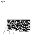
- Figure 3 is a cross section diagram of hydrogen separation composite 12 as a working example.
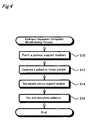
- FIG. 4 is a process diagram that shows the manufacturing process for manufacturing method A of hydrogen separation composite 12.
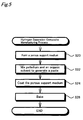
- FIG. 5 is a process diagram that shows the manufacturing process for manufacturing method B of hydrogen separation composite 12.
- Figure 6 is a process diagram that shows the manufacturing process for manufacturing method C of hydrogen separation composite 12.
- Figure 7 is an explanatory diagram that shows the structure of the flow path of fuel gas generating device 10.
- Figure 8 is an explanatory diagram that shows the hydrogen partial pressure on the chemical reaction unit side and the purge side.
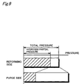
- Figure 9 is an explanatory diagram that shows the conditions relating to pressure on the reforming side and the purge side.
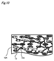
- Figure 10 is a cross section diagram of hydrogen separation composite 12A as a first variation example.
- Figure 11 is a process diagram that shows the manufacturing method of hydrogen separation composite 12A.
- Figure 12 is a cross section diagram of hydrogen separation composite 12B as a second variation example.
- Figure 13 is a cross section diagram of a hydrogen separation composite as a third variation example.
- Figure 14 is an explanatory diagram that shows the flow path of the purge gas as a first variation example.
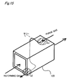
- Figure 15 is an explanatory diagram that shows the flow path of the purge gas as a second variation example.
- Figure 16 is an explanatory diagram that shows the fuel cell system as a variation example.
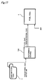
- Figure 17 is an explanatory diagram that shows the schematic structure of a fuel cell system as a second working example.
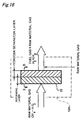
- Figure 18 is an explanatory diagram that shows the schematic structure of fuel gas generating device 10A.
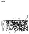
- Figure 19 is a cross section diagram of hydrogen separation composite 22.
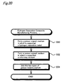
- Figure 20 is a process diagram of manufacturing method D of hydrogen separation composite 22.
- Figure 21 is a process diagram of manufacturing method E of hydrogen separation composite 22.
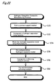
- Figure 22 is a process diagram of manufacturing method F of hydrogen separation composite 22.
- Figure 23 is an explanatory diagram that shows the categories of hydrogen generating and separation mechanisms.
- Figure 24 is an explanatory diagram that shows the structure of hydrogen generating and separation mechanism 100 as structure 1.
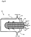
- Figure 25 is an explanatory diagram that shows the structure of separation pipe 110.
- Figure 26 is an explanatory diagram that shows the structure of hydrogen generating and separation mechanism 150 as structure 2.
- Figure 27 is an explanatory diagram that shows the structure of separation pipe 160.
- Figure 28 is an explanatory diagram that shows the structure of hydrogen generating and separation mechanism 200 as structure 3.
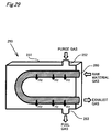
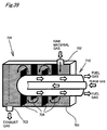
- Figure 29 is an explanatory diagram that shows the structure of hydrogen generating and separation mechanism 250 as structure 4.
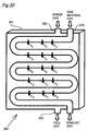
- Figure 30 is an explanatory diagram that shows the structure of hydrogen generating and separation mechanism 300 as structure 5.
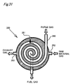
- Figure 31 is an explanatory diagram that shows the structure of hydrogen generating and separation mechanism 350 as structure 6.
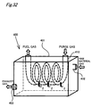
- Figure 32 is an explanatory diagram that shows the structure of hydrogen generating and separation mechanism 400 as structure 7.
- Figure 33 is an explanatory diagram that shows the structure of hydrogen generating and separation mechanism 450 as structure 8.
- Figure 34 is an explanatory diagram that shows the structure of hydrogen generating and separation mechanism 500 as structure 9.
- Figure 35 is an explanatory diagram that shows the structure of hydrogen generating and separation mechanism 550 as structure 10.
- Figure 36 is an explanatory diagram that shows the structure of hydrogen generating and separation mechanism 600 as structure 11.
- Figure 37 is an explanatory diagram that shows the structure of generating and separation pipe 610.
- Figure 38 is an explanatory diagram that shows the structure of hydrogen generating and separation mechanism 650 as structure 12.
- Figure 39 is an explanatory diagram that shows the structure of hydrogen generating and separation mechanism 700 as structure 13.
- Figure 40 is an explanatory diagram that shows the structure of hydrogen generating and separation mechanism 750 as structure 14.
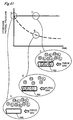
- Figure 41 is an explanatory diagram that shows the effect of stirring using fan 755.
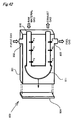
- Figure 42 is an explanatory diagram that shows the structure of hydrogen generating and separation mechanism 800 as structure 15.
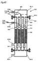
- Figure 43 is an explanatory diagram that shows the structure of hydrogen generating and separation mechanism 900 as structure 16.
- Figure 44 is an explanatory diagram that shows the structure of hydrogen generating and separation mechanism 900A as structure 17.
- Figure 45 is an explanatory diagram that shows the structure of hydrogen generating and separation mechanism 900B as structure 18.
- Figure 46 is an explanatory diagram that shows the structure of a hydrogen generating and separation mechanism as structure 19.
- FIG. 1 is an explanatory diagram that shows the schematic structure of a fuel cell system as a working example.
- the fuel cell system is constructed with the main elements of fuel cell 4 that obtains electromotive force by an electrochemical reaction using hydrogen and oxygen, and a fuel gas generating device 10 that generates from raw material gas the fuel gas that is supplied to fuel cell 4.
- Fuel cell 4 is a solid polymer film type fuel cell, and is composed from multiple layers of cells comprising an electrolytic film, a cathode, an anode, and a separator.
- the electrolytic film is a proton conductive ion exchange film formed from a solid polymer material such as a fluorocarbon resin.
- the cathode and anode are both formed using carbon cloth woven from carbon fibers.
- the separator is formed by conductive material that is gas impermeable such as dense carbon for which the carbon is compressed and that is gas impermeable.
- a flow path for fuel gas and oxidation gas is formed between the cathode and anode. Compressed air is used for the oxidation gas, and fuel gas is generated from raw materials stored in fuel tank 1 using the device structure shown below.
- raw material gas is supplied together with water and air to fuel gas generating device 10.
- Fuel gas generating device 10 first decomposes natural gas using the following reactions and generates a mixed gas that contains carbon monoxide, carbon dioxide, and hydrogen.
- the hydrogen that is the fuel gas is separated.
- steam obtained by vaporizing the water at vaporizing unit 2 is used as a purge gas that has the role of extracting only hydrogen in a stable manner and then carrying it.
- the heat source for obtaining steam at vaporizing unit 2 is obtained by burning the hydrogen and carbon monoxide contained in the rest of the mixed gas.
- a gas containing steam as a purge gas and hydrogen as a combustion gas is exhausted from fuel gas generating device 10. It is acceptable to supply this gas directly to fuel cell 4, but with this working example, the gas temperature is lowered using heat exchanger 3, steam is removed as condensed water, and after lowering the humidity, is supplied to fuel cell 4. This is because solid polymer film type fuel cell 4 has a relatively low temperature while operating, so when gas containing a large volume of steam is supplied, steam condenses at the anode part of fuel cell 4, and there is the risk of stable operation being hindered. By reducing the humidity, it is possible to suppress the concerned condensation, and to have stable operation of fuel cell 4. Note that though we have omitted an illustration, operation of each of these structural elements is controlled by a control device which has a CPU.
- FIG. 2 is an explanatory diagram that shows the internal structure of fuel gas generating device 10. This is shown based on the situation of the reaction from the raw material gas.
- the fuel gas generating device is equipped with a chemical reaction unit 11 and hydrogen separation composite 12.
- a catalyst that promotes a reforming reaction is supported at chemical reaction unit 11 according to the raw material gas.
- natural gas it is possible to use rhodium noble metal as the catalyst, and when using methanol as the raw material, it is known that CuO-ZnO catalysts and Cu-ZnO catalysts, etc. are effective.
- FIG. 3 is a cross section diagram of hydrogen separation composite 12 as a working example. This correlates to the A-A cross section in figure 2.
- Hydrogen separation composite 12 of this working example is a porous support medium of thickness 0.1 mm to 5 mm in which a hydrogen separation metal is supported. As shown in the figure, inside hydrogen separation composite 12, the ceramic fine particles 13 that form the porous support medium have gaps of approximately several hundred ⁇ , forming pores. Palladium fine particles 14 which are the hydrogen separation metal are supported inside these pores.
- palladium fine particles 14 are shown as being scattered, but in actuality, they are supported at a density of a level for which they fill the inside of the pores of the porous support medium. However, all pores are not necessarily filled.
- the mixed gas supplied from one side passes through the gaps of ceramic fine particles 13, it is sufficient to have palladium fine particles 14 supported to a degree for which the gas can pass through some of the pores filled by palladium fine particles 14 as necessary.
- the various substances having the property of selectively transmitting hydrogen can be used for the supported metal, and it is possible to use a palladium and silver alloy or a lanthanum and nickel alloy, etc. It is also possible to use alumina, silicon nitride, or silica, etc. for the ceramic fine particles.
- Hydrogen separation composite 12 of this working example can be manufactured by one of the following three manufacturing methods.
- Figure 4 is a process diagram that shows the manufacturing process for manufacturing method A of the hydrogen separation composite 12.
- Manufacturing method A is a manufacturing method called a so-called impregnation support method.
- a porous support medium used for the hydrogen separation composite is formed (step S10).
- ceramic fine particles are mixed with an organic solvent, and the molded item is baked and formed.
- a palladium nitrate solution for impregnating the formed porous support medium is generated (step S12).
- a palladium nitrate aqueous solution is used, but the type of solution can be suitably selected according to the type of hydrogen separation metal that is supported. Also, for the concentration, enough palladium to be sufficiently supported in the pores must be included, and this is adjusted according to things such as the volume, porosity, and pore diameter of the porous support medium to be impregnated.
- step S14 When an aqueous solution generated in this way is impregnated in the porous support medium (step S14), and then the porous support medium is dried, the palladium that was dissolved in the solution is precipitated, and is supported within the pores (step S16). It is also possible to perform a degassing process together in order to impregnate sufficient aqueous solution in the pores.
- FIG. 5 is a process diagram that shows the manufacturing process of manufacturing method B of hydrogen separation composite 12.
- a porous support medium is formed using the same method as manufacturing method A (step S20).
- palladium and an organic solvent are mixed to make a paste (step S22).
- the palladium is made to a fine level in advance to a level that will allow it to be supported in the pores of the porous support medium.
- the organic solvent There are no particular restrictions on the organic solvent, and a variety of resins can be used, but when mixed with palladium, it is preferable to select a material which has a viscosity that will allow a sufficient level of penetration into the pores of the porous support medium.
- step S24 When an organic solvent generated in this way is coated on the surface of the porous support medium (step S24), an organic solvent layer is formed on the surface, and organic solvent also fills the inside of the pores. In this case as well, to more reliably fill with the organic solvent, it is preferable to blow gas from the surface coated with organic solvent and to perform degassing from the opposite side to the coated one. After sufficiently filling organic solvent into the interior of the pores in this way, when the porous support medium is baked (step S26), the organic solvent is burned off, so a porous support medium for which palladium is supported inside the pores is formed.
- FIG. 6 is a process diagram that shows the manufacturing process for manufacturing method C of hydrogen separation composite 12.
- Manufacturing method C is a method with which both are manufactured at once.
- a mixed substance of ceramic fine particles, palladium fine particles, and an organic solvent is generated (step S30).
- the organic solvent There is no particular restriction on the organic solvent, and any item having a viscosity of a level which will make later formation easy can be selected.
- a polymer can be used, for example.
- this mixture is molded (step S32) and baked (step S34).
- the organic solvent is burned off, and a porous support medium in which palladium fine particles are supported in the ceramic pores is formed.
- Manufacturing method C allows completion of the formation of the porous support medium and support of the palladium with the same manufacturing process, so it has the advantage that it is possible to reduce manufacturing cost of the porous support medium. Note that with manufacturing method C, before generating the mixture at step 30, it is also possible to provide a process of supporting the palladium fine particles in the ceramic fine particles. For example, it is possible to dip the ceramic fine particles in a palladium solution and dry this to support the particles.
- hydrogen separation composite 12 of this working example by supporting palladium inside the pores, it is possible to increase the transmission speed of transmitting only hydrogen of the mixed gas. It is known that generally, the hydrogen transmission speed is proportional to the surface area for which the palladium contacts the mixed gas, and is inversely proportional to the film thickness, and with this working example, because it is possible to greatly increase the contact area for the mixed gas and palladium by supporting palladium inside the pores, it is possible to greatly increase the hydrogen transmission speed. Also, hydrogen separation composite 12 of this working example has the advantage of pin holes not occurring easily because palladium is supported inside the pores, so the film can be made thinner for hydrogen separation composite 12. With the concerned effect, if a fuel gas generating device is constructed using hydrogen separation composite 12 of this working example, it is possible to make the device more compact.
- FIG 7 is an explanatory diagram that shows the structure of the flow path of fuel gas generating device 10.
- FIG 2 we showed the structure of fuel gas generating device 10 with the gas reaction as the center as a typical example, but in reality, chemical reaction unit 11 is provided to contact hydrogen separation composite 12.
- hydrogen separation composite 12 As shown in the figure, when raw material gas is flowed in from one inlet, and a reforming reaction occurs inside chemical reaction unit 11 to generate hydrogen, that hydrogen is exhausted on the purge side through hydrogen separation composite 12.
- Figure 8 is an explanatory diagram that shows the hydrogen partial pressure on the chemical reaction unit side and on the purge side.
- the direction shown in figure 7 in other words, the direction in which the raw material gas flows, the x axis is used, and origin point O is shown as the raw material gas inlet part while point L shows the outlet part.
- Figure 8 is a figure that shows the hydrogen partial pressure for each position on the x axis.
- Figure 8 (a) shows the hydrogen partial pressure when the gas flow is made to face opposite for the chemical reaction unit side and the purge side.
- Figure 8 (b) shows the hydrogen partial pressure when both gases flow in the same direction as a comparative example.
- the reforming reaction advances as it faces downstream, so the hydrogen percentage increases and the hydrogen partial pressure increases. It is known that generally near the raw material gas inlet the reforming reaction progresses rapidly, after which the hydrogen in the mixed gas is extracted and the chemical balance is destroyed, so in ' response to this a trend is shown of having the reaction progress gradually. In comparison to this, on the purge side, as it faces downstream, the volume of extracted hydrogen increases, so the hydrogen partial pressure gradually increases.
- fuel gas generating device 10 of this working example it is possible to increase the hydrogen transmission speed if the gas flow of the chemical reaction unit side and purge side are made to face opposite. This means that it is possible to efficiently separate hydrogen and to efficiently generate hydrogen gas, so if the flow path structure of this working example is used, then it is possible to make fuel gas generating device 10 more compact.
- the flow path of chemical reaction unit 11 is constructed so that the cross section area becomes narrower as it faces from upstream to downstream.
- the flow path of the purge side is constructed so that the cross section area becomes broader as it faces from upstream to downstream.
- gas pressure is inversely proportional to the cross section area of the flow path. Therefore, with the fuel gas generating device of this working example, the flow path is constructed so that the chemical reaction unit pressure increases as it goes downstream, and the purge side pressure decreases as it goes downstream.
- FIG. 9 is an explanatory diagram that shows the conditions relating to the reforming side and purge side pressure.
- purge gas is supplied so as to satisfy simultaneously a condition of the overall pressure on the reforming side being lower than the overall pressure of the purge side, as well as the condition of the hydrogen partial pressure on the reforming side being higher than the hydrogen partial pressure on the purge side.
- the concerned conditions can be met by supplying as purge gas steam in a volume that will supplement the hydrogen partial pressure shown by cross hatching in figure 9.
- Hydrogen separation composite 21 exhibits an effect of selectively transmitting hydrogen from the side with high hydrogen partial pressure to the side with low pressure, so the condition of having the purge side hydrogen partial pressure be lower than that of the reforming side is an essential condition for separating hydrogen. Meanwhile, the condition of having the total pressure of the purge side be higher than the total pressure of the reforming side exhibits the effect of preventing leaks of mixed gas on the purge side. For example, even when there are pin holes in hydrogen separation composite 12, if the concerned pressure conditions are set, then it is possible to avoid mixed gas leaking to the purge side. Therefore, it is possible to avoid toxification of the electrode of fuel cell 4 by mixing of carbon monoxide in the fuel gas, so that stable operation of fuel cell 4 is possible.
- Figure 10 is a cross section diagram of hydrogen separation composite 12A as a first variation example.
- the fact that the structure has palladium supported in the porous support medium is the same as the hydrogen separation composite 12 of the working example, but how the support is embodied is different.
- palladium is supported in fine particle form inside the pores.
- palladium 14A is supported in film form within the pores of ceramic fine particles 13.
- FIG 11 is a process diagram that shows the manufacturing method of hydrogen separation composite 12A.
- Hydrogen separation composite 12A of the variation example is formed by, after forming a porous support medium in which palladium is supported (step S40), forming the porous support medium by baking (step S42).
- the porous support medium formed at step S40 can be manufactured by any of manufacturing methods A through C shown in the working example (see figures 4 through 6).
- a porous support medium manufactured in this way is baked, the supported palladium fine particles are partially dissolved, and form a film inside the pores.
- the palladium is supported as extremely fine particles, so when baking, it has been confirmed that a film is formed even when the temperature is not necessarily raised to the melting point.
- FIG 12 is a cross section diagram of hydrogen separation composite 12B as a second variation example.
- the concerned hydrogen separation composite 12B can be formed using a porous support medium molded to have bumps in advance using manufacturing method A and manufacturing method B shown with the working example (see figures 4 and 5). It is also possible to bake a mixed substance of ceramic fine particles, palladium fine particles, and an organic solvent after molding in a shape that has bumps using manufacturing method C shown with the working example (see figure 6).
- the second variation example by using a bumpy shape, it is possible to increase the area of contact per width W between hydrogen separation composite 12B and the mixed gas.
- the speed at which the hydrogen separation composite transmits hydrogen is known to be proportional to the contact area with mixed gas, so with the second variation example, it is possible to increase the transmission efficiency per unit width. Therefore, with this hydrogen separation composite 12B, it is possible to make fuel gas generating device 10 more compact.
- the bumps are not limited to being the wave shapes shown in figure 12.
- FIG. 13 is a cross section diagram of a hydrogen separation composite as a third variation example.
- porous support medium 17 is joined to one side of the hydrogen separation composite 12 of the working example.
- Porous support medium 17 uses ceramics of the same composition as the porous support medium that forms hydrogen separation composite 12, and ceramic fine particles 13 form pores the same as hydrogen separation composite 12.
- ceramic fine particles 13 form pores the same as hydrogen separation composite 12.
- the porosity of hydrogen separation composite 12 of the working example is high, so there are cases when the mechanical strength is insufficient.
- porous support medium 17 it is necessary to provided a thickness that can ensure the mechanical strength needed for the hydrogen separation composite.
- the joining of hydrogen separation composite 12 and porous support medium 17 must be done in a way that will allow exchange of gas between these items.
- ceramic fine particles and an organic solvent can be mixed to make a paste that is coated on both items, and this is baked. It is also possible to mold porous support medium 17 before baking onto hydrogen separation composite 12, and then to bake the whole thing.
- Figure 14 is an explanatory diagram that shows the flow path of purge gas as a first variation example. Differing from figure 7, this shows the purge gas in a state of flowing over the top surface of hydrogen separation composite 12. With the first variation example, the purge gas flows in switchback fashion along hydrogen separation composite 12. In areas such as area a shown by cross hatching in the figure, the flow of the purge gas and the flow of the mixed gas partially face opposite each other. It is not necessary to flow the purge gas and mixed gas so that they face opposite each other along the entire area of hydrogen separation composite 12, and it is acceptable to have them flow partially facing each other in this way.
- FIG 15 is an explanatory diagram that shows the flow path of the purge gas as a second variation example.
- hydrogen separation composite 12D is formed in a tube shape, and mixed gas passes through its interior.
- Purge gas is passed through so as to enclose the periphery of hydrogen separation composite 12D.
- areas b1 and b2 in the figure purge gas and mixed gas flow in directions opposite each other. It is also possible to construct one flow path in this way three dimensionally. It is also possible to pass the purge gas through in spiral form. Also, as shown by the dot-dash line in figure 15, it is possible to have the purge gas flow out in a direction orthogonal to the flow of the mixed gas.
- FIG 16 is an explanatory diagram that shows a fuel cell system as a variation example.
- a fuel cell system of the working example see figure 1
- the structure provided a heat exchanger 3.
- a high temperature type fuel cell for which the operating temperature reaches 150 °C or greater was used as fuel cell 4A. This is applicable to fuel cells such as a phosphoric acid type or fused carbonate type fuel cell.
- the heat exchanger is omitted, and the mixed gas of fuel gas obtained using fuel gas generating device 10 and steam can be directly supplied to fuel cell 4A.
- FIG 17 is an explanatory diagram that shows the schematic structure of a fuel cell system as a second working example.
- first working example we showed an example of using steam as the purge gas for fuel gas generating device 10.
- second working example a raw material gas is used as the purge gas.
- elements provided with the first working example such as vaporizer 2 for generating steam and heat exchanger 3 for condensing steam of the supplied gas to fuel cell 4 become unnecessary (see figure 1), so the overall system structure can be simplified.
- the structure of fuel gas generating device 10A is also different from the first working example.
- the first working example we showed an example where mixed gas was generated using chemical reaction unit 11, and only the hydrogen in this was extracted using hydrogen separation composite 12.
- fuel gas generating device 10 was mainly composed from two structural elements.
- the second working example we will show an example of a case where both the work of the reforming reaction and hydrogen separation are performed inside the hydrogen separation composite.
- a structure that uses raw material gas as the purge gas is not unique to fuel gas generating device 10A of the second working example, but can also be applied to the first working example.
- FIG 18 is an explanatory diagram that shows the schematic structure of fuel gas generating device 10A.
- Fuel gas generating device 10A is formed using hydrogen separation composite 22 that is a single structural element.
- hydrogen separation composite 22 of the second working example is constructed in a form where two layers, the reforming layer and the hydrogen separation layer, are joined internally.
- raw material gas and steam are supplied to this hydrogen separation composite 22, a reforming reaction occurs at the reforming layer, and hydrogen, carbon monoxide, and carbon dioxide are generated. Mixed gas generated in this way is supplied as is to the hydrogen separation layer and only hydrogen is extracted.
- raw material gas is used as the purge gas for extracting hydrogen, so gas that contains fuel gas and raw material gas is exhausted from fuel gas generating device 10A.
- the fact that fuel gas is generated by performing the two effects of a reforming reaction and hydrogen separation on raw material gas inside hydrogen separation composite 22 formed as a single unit in this way is the characteristic point of fuel gas generating device 10A of the second working example.
- FIG 19 is a cross section diagram of hydrogen separation composite 22.
- hydrogen separation composite 22 is constructed from a reforming layer and a hydrogen separation layer.
- the hydrogen separation layer has the same structure as the hydrogen separation composite of the first working example, with palladium fine particles 14 that are the hydrogen separation metal supported in the pores of a porous support medium constructed using ceramic fine particles 13.
- palladium fine particles 14 are shown with gaps open, but in reality, as with the first working example, it is supported at a density of a level that will fill the pores of the porous support medium.
- rhodium fine particle 16 that are the catalyst are supported in the pores of a porous support medium constructed in the same way using ceramic fine particles 15.
- the reforming layer is constructed with the size of the ceramic fine particles 15 smaller than those of the hydrogen separation layer, and with the diameter of the pores and the porosity greater than those of the hydrogen separation layer.
- rhodium fine particles 16 are not supported at a high density that would completely fill the pores, but instead are supported in a less dense state than the hydrogen separation layer. In this way, it is possible to sufficiently diffuse raw material gas inside the reforming layer by adjusting the pore diameter, porosity, and density of rhodium fine particles 16 at the reforming layer.
- the composition of the ceramic fine particles for the reforming layer and hydrogen separation layer are also changed.
- the hydrogen separation layer palladium fine particles 14 are reliably supported in a state that fills the pores, so alumina particles that have a property of being very adaptable to palladium fine particles 14 is used as ceramic fine particles 13.
- ceria particles which have the properties of increasing the catalytic activity of the rhodium fine particles and of promoting the reforming reaction are used as ceramic fine particles 15. By doing this, the reforming effect and hydrogen separation effect of the layers will work more effectively.
- Hydrogen separation composite 22 can be manufactured using one of the three manufacturing methods described below.
- Figure 20 is a process diagram of manufacturing method D of hydrogen separation composite 22.
- a porous support medium in which is supported hydrogen separation metal and a porous support medium in which is supported a catalyst are manufactured separately (steps S50 and S52), and these are joined together as a single unit (step S54).
- the two types of porous support medium can be put together and baked.
- manufacturing methods A through C described with the first working example see figures 4 through 6.
- the hydrogen separation layer and reforming layer are manufactured separately, so there is the advantage that it is easier to apply a state that is suitable for the effect for the manufacturing of each layer.
- FIG 21 is a process diagram of manufacturing method E of hydrogen separation composite 22.
- the point of difference with manufacturing method D is that the hydrogen separation layer and reforming layer are manufactured together.
- manufacturing method E first, a mixture of a hydrogen separation metal, a catalyst, ceramic fine particles, and an organic solvent is generated (step S60).
- the composition of the ceramic fine particles is changed for the hydrogen separation layer and the reforming layer, the two types of ceramic fine particles used for each of these are mixed. At this time, it is preferable that the two types of ceramic fine particles have a different specific gravity.
- step S62 After performing centrifugal separation on a mixture generated in this way to separate the hydrogen separation metal and catalyst (step S62), this is molded and baked (step S64).
- step S64 When there are two types of ceramic fine particles with different specific gravity in the mixture, these fine particles are also separated together with the hydrogen separation metal and the catalyst.
- the specific gravity of the hydrogen separation metal is greater than the specific gravity of the catalyst, it is necessary to make the specific gravity of the ceramic fine particles of the hydrogen separation layer greater than the specific gravity of the ceramic fine particles of the reforming layer, and when the size relationship of the specific gravity of the hydrogen separation metal and the catalyst is the reverse of this, then the size relationship of the specific gravity of the ceramic fine particles of each layer must be set to match this.
- manufacturing method E it is possible to manufacture both the hydrogen separation layer and the reforming layer at once, so it is possible to simplify the manufacturing process for hydrogen separation composite 22, giving the advantage of being able to reduce manufacturing costs.
- FIG 22 is a process diagram of manufacturing method F of hydrogen separation composite 22.
- a hydrogen separation metal and a catalyst are sequentially impregnated into a porous support medium.
- a porous support medium is manufactured (step S70), and then a solution of hydrogen separation metal is impregnated (step S72).
- the hydrogen separation metal is moved inside the porous body using fluid pressure (step S74).
- the porous support medium is dried in this state, and a hydrogen separation layer is formed by precipitating the hydrogen separation metal (step S76).
- Step S74 is a process that is performed with the goal of biasing the impregnated solution inside the porous support medium, so when blowing gas, it is necessary to blow using a pressure that is sufficient to move the solution and at a pressure of a level whereby the gas will not be blown out anywhere else.
- the process of step S74 can also be realized by degassing from one surface, and making an environment for which there is a pressure difference on both sides of the porous support medium.
- a catalyst solution is impregnated in the porous support medium (step S78), and if this is dried and the catalyst is precipitated, it is possible to form a reforming layer (step S80). Note that when forming a reforming layer, it is not necessary to perform the process of moving the solution using fluid pressure.
- the concerned hydrogen separation composite can also be manufactured using manufacturing method D, for example, by forming a porous support medium in which a hydrogen separation metal is supported, then baking this porous support medium, and after supporting the hydrogen separation metal in film form, joining this with the reforming layer. It is also suitable to mold hydrogen separation composite 22 of the second working example in a shape having bumps like that shown in figure 12, or to join with a porous support medium for which mechanical strength can be ensured as shown in figure 13.
- the reforming device is constructed by providing items such as a mechanism that exhausts mixed gas and fuel gas after the supply and reaction of raw material gas and purge gas, respectively, and a mechanism that maintains the temperature required for a chemical reaction.
- Figure 23 is an explanatory diagram that shows the categories of hydrogen generating and separation mechanism.
- the categories according to things such as the flow path structure and the type of gas that flows in the flow path.
- the flow path structure can be broadly categorized into cases of using a single pipe, a double pipe having a dual structure, or a flow path formed inside a porous monolith, and for each of these, it is possible to categorize into cases of forming a flow path that is a straight pipe with no curves, or cases of forming a flow path as a bent pipe with curves.
- each flow path structure it is possible to categorize into cases of flowing purge gas and cases of flowing raw material gas inside the flow path.
- the structure extracts the hydrogen from outside the flow path into the flow path by flowing purge gas inside the flow path.
- the structure extracts hydrogen by performing a hydrogen generating reaction in the flow path using a reforming reaction, etc., and by flowing purge gas outside the flow path.
- Figure 32 shows the correspondence between the structures shown as examples and the categories.
- the blank categories in figure 23 are items for which examples have been omitted because they are structures for which it is possible to inferred from structures that are specifically shown as examples. This does not mean that these are categories that cannot be realized.
- FIG 24 is an explanatory diagram that shows the structure of hydrogen generating and separation mechanism 100 as structure 1.
- Figure 24 (a) is an oblique diagram of the external appearance of the mechanism.
- Figure 24 (b) is a cross section diagram cut at the symmetric plane.
- hydrogen generating and separation mechanism 100 is constructed from main body 101 and multiple separation pipes 110.
- Main body 101 is formed as a porous material monolith in cylinder form.
- a reforming catalyst is supported in the porous material.
- Raw material gas supply port 102 is joined to main body 101, and raw material gas such as a hydrocarbon is supplied to the porous pores. This raw material gas generates a reforming reaction by the effect of the reforming catalyst supported in the porous material, and generates a mixed gas that contains hydrogen.
- FIG. 25 is an explanatory diagram that shows the structure of a separation pipe 110.
- a separation pipe 110 is formed using the hydrogen separation composite explained previously with the first working example and the second working example. Specifically, as shown in figure 25 (a), with separation pipe 110, a separation film 112 in which palladium is supported is provided on the surface of cylindrical porous support medium 111. The various methods explained previously with the working examples can be used as the method for forming separation film 112.
- a hollow separation pipe 110 is used, but as shown in figure 25 (b), it is also possible to form the pipe interior using a porous material.
- separation pipe 110A is constructed by providing separation film 112 on the surface of porous support medium 111A formed in a cylinder shape. With the variation example, there are the advantages that forming the separation pipe 110A is easy, and it is possible to increase the strength. With structure 1, it is also possible to use either separation pipe 110 or 110A.
- the hydrogen in the mixed gas generated by the main body 101 is extracted into separation pipe 110 inside hole 105.
- This hydrogen is carried downstream as fuel gas together with the purge gas.
- the gas that remains inside main body 101, in other words, the gas after hydrogen has been separated form the mixed gas, is exhausted from exhaust port 103.
- the surface of main body 101 is sealed so that mixed gas does not flow out.
- the juncture of raw material gas supply port 102 (area A in the figure), the juncture of exhaust port 103, and the gap between the hole for inserting separation pipe 110 and separation pipe 110 (area B in the figure) are also sealed to avoid gas leaks. It is also possible to cover hydrogen generating and separation mechanism 100 with an airtight casing.
- Structure 1 is constructed by inserting single pipe separation pipe 110 with no curves, so there is the advantage that manufacturing is easy. It is possible to extract hydrogen at separation pipe 110 while reforming at main body 101, so there is also the advantage of being able to make the device more compact. As explained using the first working example, etc., by using purge gas, there is also the advantage of having high hydrogen separation efficiency.
- main body 101 that performs the reforming reaction is formed by a porous material monolith.
- Various structures can be used for main body 101.
- separation pipe 110 as well, this is not limited to being a cylinder, and a variety of cross section shapes can be used.
- the number of and placement of the separation pipes 110 are not restricted to the example shown in figure 24.
- Figure 26 is an explanatory diagram that shows the structure of hydrogen generation and separation mechanism 150 as structure 2.
- a cross section diagram of the symmetric plane is shown. The external appearance is the same as that of structure 1.
- the purge gas and raw material gas flow sites are the reverse of those of structure 1.
- the device structure itself is the same as structure 1, and separation pipes 160 are inserted into holes 155 that are provided in main body 151 formed by a porous material monolith. Steam is supplied as purge gas from supply port 152 that is joined to the main body 151, and after hydrogen is extracted from separation pipes 160, this is exhausted from exhaust port 153 as fuel gas. At main body 151, no chemical reaction occurs, so no catalyst is supported.
- FIG 27 is an explanatory diagram that shows the structure of a separation pipe 160.
- structure 2 raw material gas is supplied inside separation pipes 160 to perform a reforming reaction, so the point of providing a catalyst differs from structure 1.
- Separation pipe 160 is constructed using the hydrogen separation composite explained with the first working example, etc.
- separation film 162 is provided on the surface of porous support medium 161.
- the inside of separation pipes 160 is filled with pellet shaped reforming catalyst 163. Because there is a porous support medium 161, reforming catalyst 163 does not directly contact separation film 162. Therefore, there is the advantage of not having the risk of the particles of reforming catalyst 163 causing damage to separation film 162 due to vibration during operation, etc. Also, the pellet shaped reforming catalyst 163 can be easily refilled, so there is the advantage of maintenance of the hydrogen generating and separation mechanism being easy.
- the catalyst of separation pipe 160 can also be supported in a porous support medium.
- Figure 27 (b) shows the structure of separation pipe 160A as a variation example. As shown in the figure, with separation pipe 160A of the variation example, separation film 162A is formed on the surface of a porous support medium formed in a cylinder shape. A reforming catalyst is supported in porous support medium 161A. If the concerned structure is used, there is the advantage that evenly supporting the reforming catalyst is easy, and that it is possible to ensure the strength of separation pipe 160.
- FIG 28 is an explanatory diagram that shows the structure of a hydrogen generating and separation mechanism 200 as structure 3. This shows an oblique diagram of the state cut at the symmetric plane.
- Hydrogen generating and separation mechanism 200 of structure 3 has a U shaped separation pipe 210 that pierces into main body 201.
- the structure of separation pipe 210 is the same as that of separation pipe 110 of structure 1 (see figure 25).
- Raw material gas supply port 202 and exhaust port 203 are joined to main body 201.
- Main body 201 is an airtight container, and the interior (the part shown by cross hatching in the figure) is filled with a reforming catalyst.
- the raw material gas supplied for supply port 202 is reformed inside main body 201. Purge gas is flowed into separation pipe 210, and the hydrogen generated by main body 201 is extracted into separation pipe 210.
- Hydrogen generating and separation mechanism 200 of structure 3 has the same advantages as structure 1, such as manufacturing being relatively easy.
- Separation pipe 210 is curved in a U shape, so there is also the advantage of being resistant to heat distortion. Generally, reforming reactions are performed at high temperatures, so there is a big temperature difference between when hydrogen generating and separation mechanism 200 is operating and when it is stopped. These temperature differences invite expansion and contraction of separation pipe 210.
- the curved part of separation pipe 210 is the free end that is not fixed to main body 201, so separation pipe 210 can expand and contract with relative freedom in the axis direction due to heat. Therefore, structure 3 has the advantage of being able to suppress the possibility of damage occurring to separation pipe 210 due to heat stress.
- separation pipe 210 that has a curve can increase the capacity efficiency.
- separation pipe 210 by having a curve, it is possible for separation pipe 210 to be efficiently housed in main body 201.
- main body 201 is constructed from an airtight container.
- Main body 201 can also be formed using a porous material in which a reforming catalyst is supported.
- FIG 29 is an explanatory diagram that shows the structure of a hydrogen generating and separation mechanism 250 as structure 4. This shows an oblique diagram of being cut at the symmetric plane.
- Hydrogen generating and separation mechanism 250 of structure 4 is different from structure 3 in that purge gas flows into main body 251 and reforming is performed from the raw material gas inside separation pipe 260. There is no catalyst supported inside main body 251.
- the structure of separation pipe 260 the same as that of separation pipe 160 of structure 2 (see figure 27).
- there are advantage s such as manufacturing being easy, being resistant to heat distortion, and having excellent capacity efficiency and hydrogen separation efficiency.
- FIG. 30 is an explanatory diagram that shows the structure of hydrogen generating and separation mechanism 300 as structure 5. This shows an oblique diagram of the state cut at the symmetric plane.
- the mechanism of structure 5 With the mechanism of structure 5, multiple separation pipes 310 that have a curve pierce into main body 301.
- the structure of separation pipes 310 is the same as that of separation pipe 160 of structure 2 (see figure 27).
- Supply port 302 and exhaust port 303 are joined to main body 301.
- the hydrogen that is generated inside separation pipes 310 by the purge gas supplied from supply port 302 is extracted into main body 301.
- the structure has multiple curves, it is possible to further increase the capacity efficiency of separation pipes 310, and also to make the device thinner.
- the number and shape of the curves of separation pipes 310 are not limited to those shown in the figure.
- Figure 31 is an explanatory diagram that shows the structure of hydrogen generating and separation mechanism 350 as structure 6. It shows a cross section diagram shown from the top.
- Main body 351 is a circular container, and supply port 352 and exhaust port 353 are attached tot his.
- Main body 351 has a reforming catalyst supported in it for use in reforming the raw material gas supplied from supply port 352.
- Separation pipe 360 is formed in a spiral shape, and purge gas is supplied inside it.
- the structure of separation pipe 360 is the same as that of structure 1 (see figure 25).
- FIG 32 is an explanatory diagram that shows the structure of hydrogen generating and separation mechanism 400 as structure 7.
- Main body 401 is an airtight container, and supply port 402 and exhaust port 403 are joined to it.
- Main body 401 has a reforming catalyst supported in it for reforming the raw material gas that is supplied from supply port 402.
- Separation pipe 410 is formed in a spiral shape, and purge gas is supplied to its interior.
- the structure of separation pipe 410 is the same as that of structure 1 (see figure 25).
- separation pipe 410 is placed three dimensionally in this way, then it is possible to further increase the capacity efficiency of separation pipe 410, and it is possible to increase the hydrogen separation efficiency.
- a separation pipe 410 having many curves it is preferable to use a metal porous material as the porous support medium.
- the ductility of metal makes it easier to form separation pipe 410 and also has the advantage of making it easier to avoid damage due to vibration during operation.
- Use of a metal porous material is not limited to structure 7, and is effective when providing curves in separation pipes.
- Figure 33 is an explanatory diagram that shows the structure of hydrogen generating separation mechanism 450 as structure 8.
- the mechanism of structure 8 is structured with separation pipe 460, which is formed as a double pipe, inserted into main body 451.
- Supply port 452 and exhaust port 453 are joined to main body 451.
- Main body 451 is an airtight container filled with a reforming catalyst, and raw material from supply port 452 is reformed here. It is also possible to form main body 451 with a porous material in which a reforming catalyst is supported.
- Separation pipe 460 is constructed with inner pipe 461 for which both ends are open inserted into outer pipe 462 for which only one end is open.
- Outer pipe 462 and inner pipe 461 are formed in the same way as separation pipe 110 of structure 1 (see figure 25). Outer pipe 462 and inner pipe 461 are fixed at the right side in the figure.
- Purge gas is supplied to inner pipe 461, and extracted from outer pipe 462 is fuel gas for which the hydrogen generated by main body 451 is extracted.
- the flow of inner pipe 461 and outer pipe 462 can be the reverse as well.
- separation pipe 460 is structured as a double pipe for which free expansion and contraction due to heat is possible for inner pipe 461 and outer pipe 462, so there is the advantage that it is possible to further reduce the effects due to heat distortion.
- steam as the purge gas
- water is sprayed in inner pipe 461.
- separation pipe 460 is exposed to a high temperature atmosphere, so the water sprayed by that heat is vaporized. Water is vaporized by the heat from the fuel gas in outer pipe 462 being absorbed, so the fuel gas temperature decreases according to the vaporization heat.
- structure 8 with this effect, it is possible to have the temperature of the fuel gas more closely approach the operating temperature of the fuel cell.
- Figure 34 is an explanatory diagram that shows the structure of hydrogen generating and separation mechanism 500 as structure 9.
- the point of difference from structure 8 is that purge gas is flowed into main body 501 and reforming reactions, etc. are performed at separation pipe 510 which is formed as a double pipe.
- Main body 501 is an airtight container in which no catalyst is supported.
- Main body 501 can also be formed using a porous material. Purge gas is supplied from supply port 502, and hydrogen that was generated in separation pipe 510 is extracted and exhausted from exhaust port 503.
- Separation pipe 510 forms a double structure made from inner pipe 511 and outer pipe 512.
- Raw material gas is supplied to inner pipe 511 and exhausted from outer pipe 512.
- Inner pipe 511 and outer pipe 512 have the same structure as separation pipe 16 of structure 2 (see figure 27).
- Inner pipe 511 and outer pipe 512 are filled with a catalyst for generating hydrogen from raw material gas.
- a catalyst for reforming reactions is supported in the inner pipe 511, and a catalyst for shift reactions is supported in outer pipe 512.
- Raw material gas is exhausted through both reforming reactions and shift reactions.
- structure 9 has advantages from the perspective of advancing both reforming and shift reactions, and from the perspective of having the temperature of the extracted hydrogen approaching the operating temperature of a fuel cell. Note that for structure 9, besides combination of reforming reactions and shift reactions, it is also possible to perform selective oxidation reactions of carbon monoxide at outer pipe 512.
- FIG 35 is an explanatory diagram that shows the structure of hydrogen generating and separation mechanism 550 as structure 10.
- the point of difference from structure 9 is that single chemical reactions are performed inside separation pipe 560.
- Main body 551, supply port 552, and exhaust port 553 have the same structures as those of structure 9.
- Separation pipe 560 is formed from inner pipe 561 and outer pipe 562, and the difference from structure 9 is that a reforming catalyst is supported in both of these. Even with the concerned structure, there are the advantages of manufacturing being easy, being able to have the reforming unit and hydrogen separation unit in a single unit structure so it is possible to make the device more compact, and not being susceptible to heat distortion.
- Figure 36 is an explanatory diagram that shows the structure of hydrogen generating separation mechanism 600 as structure 11. This shows an oblique diagram of a cross section at the symmetric plane. Structure 11 is constructed with a generating and separation pipe 610 formed by a porous material monolith attached to airtight casing 601.
- FIG 37 is an explanatory diagram that shows the structure of generating and separation pipe 610.
- main body 611 of generating and separation pipe 610 is constructed in cylinder form by a porous monolith.
- holes 613 are formed without any curves, but it is also acceptable to provide them with curves.
- a hydrogen separation film is formed by the hydrogen separation composite explained previously with the first working example, etc. at holes 613 and end surface 612 of main body 611.
- the parts shown by bold lines in figure 36 are the hydrogen separation film.
- the hydrogen separation film is formed to cover the inner periphery of the holes 613 and the end surface 612.
- the separation film can be formed using various methods including an impregnation support method, a physical vapor deposition method, or a chemical vapor deposition method.
- the parts marked by cross hatching in figure 37 indicate areas where a hydrogen separation film is not formed, and the porous material can be seen.
- Pipes for supplying gas to generating and separation pipe 610 are provided in casing 601 of structure 11. As shown in figure 36, these are supply port 602 and exhaust port 603 that supply and exhaust raw material gas at the side surface of generating and separation pipe 610. Casing 601 is sealed at its junction with generating and separation pipe 610 so that raw material gas supplied from supply port 602 does not leak to end surface 612 of generating and separation pipe 610. A mechanism is also provided that prevents leaking of gas supplied from supply port 602 to exhaust port 603 via the periphery of generating and separation pipe 610.
- Manifolds 604 and 605 are provided in the axis direction of casing 601 to supply and exhaust purge gas. As shown by the arrow in figure 36, the purge gas supplied from manifold 604 passes out of holes 613 of generating and separation pipe 610, and with the hydrogen generated by reforming at main body 611 extracted, is exhausted from manifold 605.
- Figure 38 is an explanatory diagram that shows the structure of hydrogen generating and separation mechanism 650 as structure 12.
- the key points of the structure are the same as structure 4.
- the point of difference from structure 4 is that a partition 654 is provided in main body 651 to control the flow of purge gas.
- purge gas is supplied from supply port 653, and after flowing along partition 654, is exhausted from exhaust port 652. Meanwhile, the raw material gas flows inside separation pipe 660 in the direction shown by the filled in arrows in the figure. In the area where purge gas flows along partition 654, the mixed gas inside the separation pipe and the purge gas flow in opposing directions. As explained previously with figure 7, if the flow of the mixed gas and purge gas is made to be in opposing directions, then it is possible to expand the hydrogen partial pressure of both, and to increase the hydrogen separation efficiency. By using this effect, structure 12 has the advantage of being able to efficiently separate hydrogen. Note that with structure 12, it is also possible to flow purge gas to separation pipe 660 and to supply raw material gas to main body 651.
- Figure 39 is an explanatory diagram that shows the structure of hydrogen generating and separation mechanism 700 as structure 13.
- the key parts of the structure are the same as those of structure 8.
- the point of difference with structure 8 is that a partition 704 is provided at main body 701 to control the flow of purge gas.
- purge gas flows from the inner pipe toward the outer pipe in separation pipe 710 which is formed as a double pipe.
- the raw material gas is supplied from supply port 702, and after having the flow direction turned multiple times by partition 704, is exhausted from exhaust port 703.
- the number and shape of partition 704 are not limited to the example shown in the figure.
- the raw material gas flows in a direction orthogonal to separation pipe 710. It has been confirmed through experiments that there is an increase in the hydrogen separation efficiency by flowing in this direction. Note that with structure 13, it is also possible to perform reforming inside separation pipe 710 and to supply purge gas to main body 701.
- the structure is not restricted to having the raw material gas in a state flowing in a strictly orthogonal direction to separation pipe 710, but can also flow in a direction that has a slope in relation to separation pipe 710.
- a vane instead of partition 704.
- Figure 40 is an explanatory diagram that shows the structure of hydrogen generating and separation mechanism 750 as structure 14. This shows an oblique diagram of the cross section when cut at the symmetric plane.
- the key points of the structure are the same as those of structure 3.
- the point of difference from structure 3 is that a fan 755 that stirs the gas is provided inside main body 751.
- a reforming catalyst is filled or supported in main body 751, and the raw material gas supplied from supply port 752 is reformed inside main body 751, and after the hydrogen is extracted, it is exhausted from exhaust port 753.
- the purge gas is supplied to separation pipe 760 and hydrogen is extracted from main body 751.
- a gauge 754 is provided at the front of fan 755.
- Fan 755 is driven by motor 756 which is provided outside main body 751.
- Motor 756 is not limited to this structure, and can also be driven using output from a battery or fuel cell.
- Figure 41 is an explanatory diagram that shows the stirring effect of fan 755. This shows the change over time in hydrogen partial pressure near separation pipe 760. The solid line shows changes when operating fan 755, and the dotted line shows the changes when not using fan 755.
- Figure 42 is an explanatory diagram that shows the structure of hydrogen generating and separation mechanism 800 as structure 15. This shows an oblique diagram of the state cut at the symmetric plane.
- the key points of the structure are the same as those of structure 4.
- purge gas flows from supply port 802 to exhaust port 803.
- a reforming catalyst is filled in separation pipe 810, and this reforms the raw material gas.
- the point of difference with structure 4 is that a removable part 811 is provided for maintenance at separation pipe 810.
- the curved part of separation pipe 810 can be pulled out in the axis direction from the juncture with the straight part. By pulling out removable part 811, it is possible to easily perform maintenance such as exchanging the catalyst that fills this part. If removable part 811 is pulled out, it is also easy to exchange the catalyst inside the straight part of separation pipe 810.
- Main body 801 has a lid 804 provided on the side at which removable part 811 is pulled out to make this maintenance possible. During maintenance, lid 804 is removed and removable part 811 is pulled out. To keep an airtight state, the space between lid 804 and main body 801 is sealed.
- structure 15 in addition to the same advantages of structure 4 such as increasing hydrogen separation efficiency, there is also the advantage of having excellent maintainability. This is effective for use on structures that have a catalyst filled or supported in separation pipe 810. It is also possible to use this for a structure that flows purge gas to separation pipe 810 and performs reforming at main body 801. Note that structure 15 can also be used on various structures for which removal is possible upstream or downstream from the curved part. With figure 42, we showed an example of a structure that pulls out in the axis direction, but the structure in not limited to this.
- Figure 43 is an explanatory diagram that shows the structure of hydrogen generation and separation mechanism 900 as structure 16. This shows a cross section diagram with the cut at the symmetric plane. We showed an example of using a bellows as a heat stress suppression mechanism to avoid damage to the hydrogen separation pipe due to heat during operation.
- Hydrogen generating and separation mechanism 900 is formed by incorporation of a porous monolith 950 and hydrogen separation pipe 910 in a case.
- Porous monolith 950 has a reforming catalyst supported in it.
- Hydrogen separation pipe 910 is a pipe formed by a porous support medium in which a hydrogen separation metal is supported. The structures of these are the same as structure 1 (see figure 24).
- the case is constructed by fastening covers 901A and 901B to both ends of main body 901 which is open at both ends using bolt 901C. Inserted between main body 901 and covers 901A and 901B are separators 930 and 931 that prevent leaks of purge gas and mixed gas.
- Hydrogen separation pipe 910 has an SUS pipe 911 attached to the opening of both ends, and this is joined to the holes provided on separators 930 and 931. The connection is made via bellows 920 at separator 930 on the side where purge gas is supplied.
- the inside area separated by separators 930 and 931 becomes the flow path for the raw material gas.
- the raw material gas supplied from supply port 902M passes through the periphery of bellows 920 and is supplied to porous monolith 950.
- baffle plate 906 which has multiple orifices is provided.
- the raw material gas that passes through porous monolith 950 is exhausted from exhaust port 903M.
- Baffle plate 906 achieves a guide function of controlling the specified range of movement of SUS pipe 911. Doing this allows an increase in the resistance to vibration.
- the outside area separated by separators 930 and 931 becomes the flow path of the purge gas.
- the purge gas supplied from supply port 902P is supplied to hydrogen separation pipe 910 through bellows 920, and is exhausted from exhaust port 903P.
- a baffle plate 905 having multiple orifices is provided. Note that the diameters of the orifices of baffle plates 905 and 906 are set by experimentation, etc. at each site to obtain approximately even flow volume distribution. The orifice diameters do not have to be constant.
- Bellows 920 and baffle plates 905 and 906 of structure 16 can be used selectively as necessary. It is possible to make the structure with bellows 920 omitted, or to have a structure with baffle plates 905 and 906 omitted. With structure 16, in place of bellows 920, it is also possible to use another expansion and contraction mechanism.
- Figure 44 is an explanatory diagram that shows the structure of hydrogen generating and separation mechanism 900A as structure 17. This shows an example of providing a high pressure steam layer as a heat stress suppression mechanism in place of the bellows of structure 16.
- Two separators 930A and 930B are provided on the gas supply side for hydrogen generating and separation mechanism 900A.
- Main body 901 and connector 901D are connected while sandwiching separator 930B.
- Connector 901D and cover 901A are connected while sandwiching separator 930A.
- Steam is supplied to connector 901D. The pressure of this steam is set higher than the pressure of the purge gas or raw material gas.
- Hydrogen separation pipe 910 is supported held on one side by separator 931 on the exhaust side. The other end is the free end, and this pierces through separators 930A and 930B and is open. As shown in the figure, the purge gas that is supplied from supply port 902P flows into a pipe from each opening of hydrogen separation pipe 910.
- the structure of the other parts is the same as that of structure 16.
- the steam layer of connector 901D works as a separating mechanism that prevents leaks of purge gas and raw material gas together with separators 930A and 930B. Even when there is a gap between hydrogen separation pipe 910 and separators 930A and 930B, the pressure of the steam is higher than that of the purge gas and raw material gas, so these gases do not flow into the steam layer.
- one end of hydrogen separation pipe 910 is a free end, so heat stress does not occur. Also, using the steam layer effect, it is possible to easily prevent leaks of purge gas and raw material gas while having one end of hydrogen separation pipe 910 be a free end.
- Figure 45 is an explanatory diagram that shows the structure of hydrogen generating and separation mechanism 900B as structure 18.
- a heat stress suppression mechanism instead of the bellows of structure 16, we showed an example of a case using a slide pipe.
- an outer pipe 910C with a diameter that is slightly larger than that of hydrogen separation pipe 910B is connected to separator 930 that is inserted between main body 901 and cover 901A.
- separator 930 For hydrogen separation pipe 910B, one end is inserted in this outer pipe 910C, and the other end is connected to separator 931 on the exhaust side.
- the space between outer pipe 910C and hydrogen separator 910B is sealed.
- the material of outer pipe 910C can be the same material or a different material from that of hydrogen separation pipe 910B.
- the purge gas supplied from supply port 902P passes through outer pipe 910C from separator 930 and is supplied to hydrogen separation pipe 910B.
- the structure of the other sites are the same as structure 16.
- Figure 46 is an explanatory diagram that shows the structure of a hydrogen generating and separation mechanism as structure 19. The figures shows only the area near the purge gas supply port. The other parts are the same as structure 16.
- structure 19 is provided with a deflection plate 905A.
- the flow direction of the purge gas supplied from supply port 902P is deflected from the axis direction in the circumference direction by approximately 90 degrees by deflection plate 905A.
- Deflection plates 905A are provided at multiple levels, and the flow volume distribution of the purge gas is averaged using these deflection plates 905A. Therefore, approximately equivalent purge gas is supplied to each hydrogen separation pipe.
- deflection plates 905A we showed an example of providing deflection plates 905A in three locations. From the perspective of averaging the flow volume distribution, a variety of settings are possible for the number and position of deflection plates 905A. With structure 19, a deflection plate was provided on the purge gas supply side, but it is also possible to provide one on the raw material gas supply side.
- the present invention can be used to improve the hydrogen separating performance and to make the device more compact for devices that generate hydrogen-rich fuel gas from specified raw materials that contain hydrogen atoms such as hydrocarbon, alcohol, ether, and aldehyde.
Landscapes
- Chemical & Material Sciences (AREA)
- Chemical Kinetics & Catalysis (AREA)
- Organic Chemistry (AREA)
- Engineering & Computer Science (AREA)
- Inorganic Chemistry (AREA)
- General Chemical & Material Sciences (AREA)
- Combustion & Propulsion (AREA)
- Manufacturing & Machinery (AREA)
- Electrochemistry (AREA)
- Health & Medical Sciences (AREA)
- General Health & Medical Sciences (AREA)
- Sustainable Energy (AREA)
- Sustainable Development (AREA)
- Life Sciences & Earth Sciences (AREA)
- Analytical Chemistry (AREA)
- Oil, Petroleum & Natural Gas (AREA)
- Environmental & Geological Engineering (AREA)
- Biomedical Technology (AREA)
- Materials Engineering (AREA)
- Dispersion Chemistry (AREA)
- Fuel Cell (AREA)
- Hydrogen, Water And Hydrids (AREA)
- Separation Using Semi-Permeable Membranes (AREA)
- Catalysts (AREA)
Abstract
Description
Hydrogen pole:
is a hydrogen separation composite that is structured by supporting at least a hydrogen separating metal on a porous support medium, and that selectively transmits the hydrogen in gas,
and is characterized in that said hydrogen separation metal is made smaller than the diameter of the pores of said porous support medium, and is supported in a state where the pores of said porous support medium are filled within said porous support medium.
it is also possible to support said catalyst in a less dense state than said hydrogen separation metal within said porous support medium.
it is preferable to have a structure whereby the flow path that supplies said mixed gas along said supply surface on said supply side has a cross section area that becomes narrower as it goes downstream,
and a structure whereby the flow path that transports said fuel gas along said extraction surface on said extraction surface side has a cross section area that becomes wider as it goes downstream.
it is preferable to have a carrier gas supply unit that flows the carrier gas that carries hydrogen to said extraction unit, and
to flow the carrier gas in a direction opposite the flow direction of the mixed gas at said supply unit.
a carrier flow path that carries the hydrogen separated from said mixed gas by flowing a specified carrier gas,
and for one element of said chemical reaction unit and carrier flow path to have a pipe flow path formed within the other element using the hydrogen separation composite of the present invention.
one of said chemical reaction unit or carrier flow path can be a pipe formed by the hydrogen separation composite of the present invention with this provided in a state that pierces through the interior of the other element. The cross section of the pipe does not have to be circular.
it is preferable to provide a suppression mechanism inside the other pipe that said pipe pierces through that suppresses the speed component in the same direction as the flow direction inside said pipe for the flow of that interior. For example, it is preferable to provide a mechanism that realizes a flow orthogonal to the pipe, or a mechanism that realizes a flow that faces opposite the flow in the pipe. A partition or pane, etc. can be used for the suppression mechanism. By using the concerned structure, it is possible to expand the hydrogen partial pressure difference of the hydrogen separation film and to increase the hydrogen separation rate.
it is preferable to provide at both ends of the pipe an isolation mechanism that isolates said mixed gas and the carrier gas, and at least at one end, a suppression mechanism that suppresses thermal stress of said pipe. By suppressing the thermal stress generated at the pipe by heat during operation, it is possible to avoid things such as pipe damage. Part of the pipe formed by hydrogen separation composite can have a structure that works as a suppression mechanism, or the material attached separately to the pipe can have a structure that works as a suppression mechanism.
it is possible to use a structure for which there is a monolith made of porous material on which is formed through holes,
a hydrogen separation layer for which said hydrogen separation metal is supported is formed in the porous material around said through holes,
a catalyst support unit in which is supported the catalyst used for said chemical reaction is formed at the parts except for said hydrogen separation layer in said porous material, and
said catalytic support part becomes said chemical reaction unit while said hydrogen separation layer and through holes become said carrier flow path.
a raw material supply mechanism that supplies raw material gas for which said raw material has been vaporized in said chemical reaction unit, and
a carrier gas supply mechanism that supplies said carrier gas to said carrier flow path,
it is preferable that at least at one of said raw material supply mechanism and carrier gas supply mechanism, there be provided a flow volume averaging mechanism that suppresses bias of the flow volume distribution to said chemical reaction unit or said carrier flow path. For the raw materials and carrier gas, by supplying raw material gas and carrier gas evenly, it is possible to increase the efficiency of hydrogen generation and hydrogen separation. The bias of flow volume distribution occurs more easily when the inlet cross section area of the chemical reaction unit and carrier flow path is broader than the cross section area of the pipes that supply raw material gas and carrier gas. Near the pipe outlet front, it is common for the flow volume distribution to be high, and the flow volume distribution to get lower as the distance from the outlet increases.
Claims (49)
- A hydrogen separation composite that selectively transmits hydrogen in a gas, wherein the hydrogen separation composite is characterized by:comprising a porous support medium and a hydrogen separation metal supported in said porous support medium, andsaid hydrogen separation metal being made to a finer diameter than that of the pores in said porous support medium, while also being supported in the pores of said porous support medium in a state that fills the interior of said porous support medium.
- The hydrogen separation composite according to claim 1 wherein said hydrogen separation metal is supported in film form inside said pores.
- The hydrogen separation composite according to claim 1 wherein a catalyst that can be used for the chemical reaction that generates hydrogen from a specified raw material is further supported in the pores inside said porous support medium.
- The hydrogen separation composite according to claim 3 wherein said hydrogen separation metal and said catalyst are supported in layer form inside said porous support medium.
- The hydrogen separation composite according to claim 4 wherein said catalyst is supported in a less dense state than said hydrogen separation metal inside said porous support medium.
- The hydrogen separation composite according to claim 5 wherein the physical structure of said porous support medium differs for the layer in which said hydrogen separation metal is supported and the layer in which said catalyst is supported.
- The hydrogen separation composite according to claim 4 wherein the layer in which said hydrogen separation metal is supported and the layer in which said catalyst is supported are formed from porous support mediums of different compositions.
- The hydrogen separation composite according to claim 1 characterized by having a bumpy shape in the thickness direction.
- The hydrogen separation composite according to claim 1 characterized by further having at least one surface in the thickness direction be joined to a porous material that has a thickness that can ensure mechanical strength.
- A hydrogen separation composite that selectively transmits hydrogen in a gas, wherein the hydrogen separation composite is characterized by:having a porous support medium and having a hydrogen separation metal supported in said porous support medium, andsaid hydrogen separation metal being made to a finer diameter than that of the pores in said porous support medium, while mainly being supported in the pores inside said porous support medium.
- The hydrogen separation composite according to claim 10 wherein said hydrogen separation metal is supported in film form inside said pores.
- The hydrogen separation composite according to claim 10 wherein a catalyst that can be used for the chemical reaction that generates hydrogen from a specified raw material is further supported in the pores inside said porous support medium.
- The hydrogen separation composite according to claim 12 wherein said hydrogen separation metal and said catalyst are supported in layer form inside said porous support medium.
- A method of manufacturing a hydrogen separation composite that selectively transmits hydrogen in a gas, wherein the manufacturing method comprises:a process of forming a porous support medium,a process of generating a solution that contains a substance to be supported that is to be supported in the pores of said porous support medium, anda process of impregnating said solution in said porous support medium and then mainly precipitating said substance to be supported into the pores of said porous support medium.
- A method of manufacturing a hydrogen separation composite that selectively transmits hydrogen in a gas, wherein the manufacturing method comprises:a process of forming a porous support medium,a process of refining the substance to be supported that is to be supported in the pores of said porous support medium to have the same or a smaller diameter than that of the pores of said porous support medium, of mixing with an organic solvent, and of generating a viscous paste that can penetrate into said pores, anda process of coating said paste on said porous support medium, followed by baking, and then mainly supporting said substance to be supported inside the pores of said porous support medium
- A method of manufacturing a hydrogen separation composite that selectively transmits hydrogen in a gas, wherein the manufacturing method comprises:a process of generating a mixture of the fine particles that form the porous support medium, the fine particles of the substance to be supported, and an organic solvent, anda process of molding said mixture, baking it, and mainly supporting said substance to be supported inside the pores of said porous support medium.
- The manufacturing method according to claim 16 wherein before the process of generating said mixture, there is a process of supporting the fine particles of said substance to be supported in the fine particles that form said porous support medium.
- A method of manufacturing a hydrogen separation composite that selectively transmits hydrogen in a gas, wherein the manufacturing method comprises:a process of forming a porous support medium for which hydrogen separation metal is supported in the pores, anda process of forming a film of said hydrogen separation metal inside said pores by further baking said porous support medium.
- A method of generating a mixed gas that contains hydrogen from specified raw materials using a chemical reaction, while also manufacturing a hydrogen separation composite that selectively transmits hydrogen in said mixed gas, wherein the manufacturing method comprises:(a) a process of forming a first porous support medium in which a hydrogen separation metal is supported in the pores,(b) a process of forming a second porous support medium in which a catalyst used for said chemical reaction is supported in the pores, and(c) a process of joining as a single body said first and second porous support mediums.
- The manufacturing method according to claim 19 wherein before said process (c), there is a process of baking said first porous support medium and forming a film of said hydrogen separation metal inside the pores of said porous support medium.
- A method of generating a mixed gas that contains hydrogen from specified raw materials using a chemical reaction, while also manufacturing a hydrogen separation composite that selectively transmits hydrogen in said mixed gas, wherein the manufacturing method comprises:a process of generating a mixture of the fine particles that form the porous support medium, fine particles of a hydrogen separation metal, fine particles of a catalyst used for said chemical reaction, and an organic solvent,a process of using centrifugal separation to bias the distribution of each type of fine particle in said mixture, anda process of molding and baking said mixture.
- The manufacturing method according to claim 21 wherein at least two types of fine particles of different specific gravity are contained in the fine particles that form said porous support.
- A method of generating a mixed gas that contains hydrogen from specified raw materials using a chemical reaction, while also manufacturing a hydrogen separation composite that selectively transmits hydrogen in said mixed gas, wherein the manufacturing method comprises:a process of forming a porous support medium,a process of impregnating into said porous support medium a solution that contains one of either a hydrogen separation metal or a catalyst used for said chemical reaction,a process of biasing the distribution of said solution in the thickness direction and then precipitating the elements contained in the solution by making an environment that satisfies at least one of the following two conditions for the porous support medium impregnated with said solution: the condition of having a difference between the fluid pressure that works on one side of the thickness direction and the fluid pressure that works on the other side, and the condition of applying centrifugal force in the thickness direction,and a process of impregnating a solution containing the other of said hydrogen separation metal and catalyst into said porous support membrane and then precipitating inside the pores.
- A fuel gas generating device that generates hydrogen-rich fuel gas from specified raw materials wherein the fuel gas generating device comprises:wherein said hydrogen separation composite has a porous support medium and a hydrogen separation metal supported in the pores inside said porous support medium which is made finer than the diameter of the pores of said porous support membrane.a hydrogen separation composite that selectively transmits hydrogen in a gas,a supply unit that supplies mixed gas containing hydrogen generated from said raw materials using a chemical reaction in said hydrogen separation composite, andan extraction unit that extracts hydrogen separated by said hydrogen separation composite,
- The fuel gas generating device according to claim 24 wherein
said hydrogen separation composite is further equipped with a catalyst layer in which is supported a catalyst that is used for the chemical reaction that generates hydrogen from the specified raw materials, and
said hydrogen separation composite is placed in a state in which the layer in which said catalyst is supported is in contact with said supply unit side. - The fuel gas generating device according to claim 24 wherein
said supply unit has a structure whereby the cross section area of the flow path that supplies said mixed gas becomes narrower as it goes downstream, and
said extraction unit has a structure whereby the cross section area of the flow path that carries said fuel gas becomes wider as it goes downstream. - The fuel gas generating device according to claim 24 wherein the fuel gas generating device
is equipped with a carrier gas supply unit in which carrier gas that carries hydrogen flows to said extraction unit, and
the flow direction of said carrier gas faces opposite the flow direction of the mixed gas in said supply unit. - The fuel gas generating device according to claim 27 wherein
said supply unit is a mechanism that generates said mixed gas by mixing raw materials and steam, and
said carrier gas is steam. - The fuel gas generating device according to claim 27 wherein
said supply unit is a mechanism that generates said mixed gas from raw materials, and
said carrier gas is a gas made by vaporizing said raw materials. - A fuel gas generating device that generates hydrogen-rich fuel gas from specified raw materials, wherein the fuel gas generating device comprises:wherein said supply unit and extraction unit have the pressure adjusted so that the hydrogen partial pressure of the supply unit is higher than the hydrogen partial pressure of the extraction unit, and the total pressure on the supply side is lower than the total pressure on the extraction side.a hydrogen separation composite that selectively transmits hydrogen in a gas,a supply unit that supplies a mixed gas containing hydrogen generated from said raw material using a chemical reaction to said hydrogen separation composite, andan extraction unit that extracts hydrogen that is separated using said hydrogen separation composite, and
- A fuel cell system that generates electricity using fuel gas that contains hydrogen generated by decomposing specified raw materials using a fuel gas generating device, wherein the fuel cell system comprises:the fuel gas generating device according to claim 24,a low temperature fuel cell, anda dehumidifying unit that dehumidifies the steam partial pressure in the fuel gas generated by said fuel gas generating device to a specified value or lower and supplies this to said fuel cell.
- A fuel cell system that generates electricity using fuel gas that contains hydrogen generated by decomposing specified raw materials using a fuel gas generating device, wherein the fuel cell system comprises:the fuel gas generating device according to claim 24, anda high temperature type fuel cell.
- A fuel gas generating device that generates fuel gas for fuel cells from specified raw materials, wherein the fuel gas generating device comprises:wherein said hydrogen separation composite hasa chemical reaction unit that generates a mixed gas that contains hydrogen from said raw materials,and a carrier flow path that carries hydrogen separated from said mixed gas by flowing a specified carrier gas, and whereinone of the elements of said chemical reaction unit and carrier flow path is a pipe shaped flow path that is formed inside the other element using a hydrogen separation composite that selectively transmits hydrogen in a gas,
a porous support medium and a hydrogen separation metal that is finer than the diameter of the pores of said porous support medium that is supported in the pores inside said porous support medium. - The fuel gas generating device according to claim 33 wherein said one element is a pipe formed using said hydrogen separation composite and said pipe is provided in a state piercing inside the other element.
- The fuel gas generating device according to claim 34 wherein
said carrier flow path is formed from said pipe, and
said chemical reaction unit supports a catalyst while also being formed by a porous material monolith provided with holes in which the pipe that is said carrier flow path is inserted. - The fuel gas generating device according to claim 34 wherein said chemical reaction unit is formed with a catalyst supported inside said pipe.
- The fuel gas generating device according to claim 34 wherein said pipe is made in a form having a curved pipe inside said other element.
- The fuel gas generating device according to claim 37 wherein the hydrogen separation composite that forms said pipe is a composite that uses a metal porous material as said porous support medium.
- The fuel gas generating device according to claim 37 wherein said pipe is equipped with a mechanism that allows removal of said curved part.
- The fuel gas generating device according to claim 34 wherein said pipe is a double pipe for which an inner pipe for which both ends are open is inserted into an outer pipe for which one end is open.
- The fuel gas generating device according to claim 40 wherein
the structure is such that with said double pipe, said chemical reaction unit is equipped with a reforming catalyst for reforming reactions in said inner pipe, and is equipped with a catalyst for a reaction to reduce carbon monoxide in the outer pipe. - The fuel gas generating device according to claim 34 wherein inside said other element which is pierced by said pipe, there is a suppression mechanism that, for that internal flow, suppresses the speed elements of the same direction as the flow direction within said pipe.
- The fuel gas generating device according to claim 34 wherein there is a stirring mechanism that stirs gas inside said other element that said pipe pierces.
- The fuel gas generating device according to claim 34 wherein
there is a separating mechanism that separates said mixed gas and carrier gas at both ends of said pipe, and
there is a suppression mechanism that suppresses heat stress of said pipe at least at one end of said pipe. - The fuel gas generating device according to claim 44 wherein
one end of said pipe pierces said separating mechanism and this is supported as the free end that works as said suppression mechanism. - The fuel gas generating device according to claim 45 wherein
the separating mechanism on the side on which said suppression mechanism is provided is a high pressure gas layer that supplies to both items an inert gas that has higher pressure than that of said mixed gas and carrier gas. - The fuel gas generating device according to claim 44 wherein
said suppression mechanism is an expansion and contraction mechanism that can absorb heat distortion so that the overall length that includes said pipe and said suppression mechanism is roughly constant. - The fuel gas generating device according to claim 33 wherein
the fuel gas generating device has a porous material monolith on which is formed through holes,
a hydrogen separation layer in which is supported said hydrogen separation metal is formed inside the porous substance around said through holes,
catalyst supporting areas in which a catalyst used for said chemical reaction is supported are formed at areas other than said hydrogen separation layer inside said porous material, and
wherein said catalyst supporting areas become said chemical reaction unit and said hydrogen separation unit, and the through holes become said carrier flow path. - The fuel gas generating device according to claim 33 wherein the fuel gas generating device comprises:a raw material supply mechanism that supplies to said chemical reaction unit raw material gas for which said raw materials have been vaporized, anda carrier gas supply mechanism that supplies said carrier gas to said carrier flow path, and whereinthere is provided at least at one of said raw material supply mechanism and carrier gas supply mechanism a flow volume averaging mechanism that suppresses bias of the flow volume distribution to said chemical reaction unit or said carrier flow path.
Applications Claiming Priority (7)
| Application Number | Priority Date | Filing Date | Title |
|---|---|---|---|
| JP32848099 | 1999-11-18 | ||
| JP32848099 | 1999-11-18 | ||
| JP2000137637 | 2000-05-10 | ||
| JP2000137637 | 2000-05-10 | ||
| JP2000237297 | 2000-08-04 | ||
| JP2000237297A JP2002033113A (en) | 1999-11-18 | 2000-08-04 | Fuel gas generator for fuel cell and composite material for hydrogen separation |
| PCT/JP2000/007915 WO2001036077A1 (en) | 1999-11-18 | 2000-11-09 | Device forming fuel gas for fuel cell and composite material for hydrogen separation |
Publications (3)
| Publication Number | Publication Date |
|---|---|
| EP1258283A1 true EP1258283A1 (en) | 2002-11-20 |
| EP1258283A4 EP1258283A4 (en) | 2003-07-02 |
| EP1258283B1 EP1258283B1 (en) | 2007-02-21 |
Family
ID=27340295
Family Applications (1)
| Application Number | Title | Priority Date | Filing Date |
|---|---|---|---|
| EP00974892A Expired - Lifetime EP1258283B1 (en) | 1999-11-18 | 2000-11-09 | Composite material for fuel gas formation for a fuel cell and method of its production |
Country Status (5)
| Country | Link |
|---|---|
| US (1) | US7255721B1 (en) |
| EP (1) | EP1258283B1 (en) |
| JP (1) | JP2002033113A (en) |
| DE (1) | DE60033571T2 (en) |
| WO (1) | WO2001036077A1 (en) |
Cited By (6)
| Publication number | Priority date | Publication date | Assignee | Title |
|---|---|---|---|---|
| EP1334764A2 (en) | 2002-02-04 | 2003-08-13 | Toyota Jidosha Kabushiki Kaisha | Hydrogen-permeable membrane and manufacturing method of the same |
| EP1568409A1 (en) * | 2004-02-27 | 2005-08-31 | Mikuni Corporation | Hydrogen-permeable membrane and process for production thereof |
| WO2005057711A3 (en) * | 2003-12-08 | 2005-10-06 | Toyota Motor Co Ltd | Fuel cell manufacturing method and fuel cell |
| WO2008056803A2 (en) | 2006-11-06 | 2008-05-15 | Ngk Insulators, Ltd. | Separation membrane-porous material composite and method for manufacturing the same |
| FR2948295A1 (en) * | 2009-07-24 | 2011-01-28 | Technologies Avancees & Membranes Ind | Membrane for tangential filtration of fluid, has separation phase corresponding to porous support zone whose average pore diameter is reduced, due to presence of inorganic particles connected together and to support by bridging |
| WO2011056418A3 (en) * | 2009-10-28 | 2011-06-30 | University Of Florida Research Foundation, Inc. | Fabrication of dual structure ceramics by a single step process |
Families Citing this family (19)
| Publication number | Priority date | Publication date | Assignee | Title |
|---|---|---|---|---|
| JP4171978B2 (en) * | 2002-05-27 | 2008-10-29 | ソニー株式会社 | Fuel reformer and manufacturing method thereof, electrode for electrochemical device, and electrochemical device |
| JP4537685B2 (en) * | 2003-10-24 | 2010-09-01 | 大日本印刷株式会社 | Membrane reactor for hydrogen production |
| US7465336B2 (en) * | 2005-06-09 | 2008-12-16 | United Technologies Corporation | Fuel deoxygenation system with non-planar plate members |
| JP5395322B2 (en) * | 2005-09-30 | 2014-01-22 | 日本精線株式会社 | Hydrogen separation element |
| JP4819537B2 (en) * | 2006-03-15 | 2011-11-24 | 日本碍子株式会社 | Permselective membrane reactor and hydrogen production method using the same |
| JP5057684B2 (en) * | 2006-03-31 | 2012-10-24 | 日本特殊陶業株式会社 | Hydrogen production equipment |
| JP5057685B2 (en) * | 2006-03-31 | 2012-10-24 | 日本特殊陶業株式会社 | Hydrogen separation device and hydrogen production device |
| JP2008021596A (en) * | 2006-07-14 | 2008-01-31 | Ngk Spark Plug Co Ltd | Solid electrolyte fuel cell module |
| US20090020013A1 (en) * | 2007-07-20 | 2009-01-22 | Sloan Michael A | Membrane based deoxygenator for processing fluids |
| JP4808693B2 (en) * | 2007-10-16 | 2011-11-02 | 大日本印刷株式会社 | Hydrogen permeable membrane, fuel cell and hydrogen reformer |
| DE102008031092A1 (en) * | 2008-07-01 | 2010-01-07 | Linde Aktiengesellschaft | Method and device for generating hydrogen |
| US20100059434A1 (en) * | 2008-09-05 | 2010-03-11 | Hpd, Llc | Abrasion Resistant Membrane Structure and Method of Forming the Same |
| JP5410936B2 (en) * | 2009-12-01 | 2014-02-05 | 日本特殊陶業株式会社 | Hydrogen production equipment |
| JP5410937B2 (en) * | 2009-12-01 | 2014-02-05 | 日本特殊陶業株式会社 | Hydrogen production equipment |
| NL2006245C2 (en) * | 2011-02-18 | 2012-08-21 | Stichting Energie | MEMBRANE REACTOR AND PROCESS FOR THE PRODUCTION OF A GASEOUS PRODUCT WITH SUCH REACTOR. |
| KR20140123218A (en) * | 2013-04-12 | 2014-10-22 | 삼성전자주식회사 | Hydrogen separation membrane and device including hydrogen separation membrane |
| JP2016147226A (en) * | 2015-02-12 | 2016-08-18 | 株式会社Screenホールディングス | Catalyst structure, method for manufacturing catalyst structure, and manufacturing apparatus |
| US20200075962A1 (en) * | 2018-09-04 | 2020-03-05 | Toyota Jidosha Kabushiki Kaisha | Manufacturing method and manufacturing apparatus for gas diffusion layer |
| DE102023206019A1 (en) * | 2023-06-27 | 2025-01-02 | Forschungszentrum Jülich GmbH | Structured membrane unit, manufacturing process and preparation process |
Family Cites Families (27)
| Publication number | Priority date | Publication date | Assignee | Title |
|---|---|---|---|---|
| JPS3817806B1 (en) * | 1961-08-11 | 1963-09-11 | ||
| JPS425642B1 (en) * | 1964-07-23 | 1967-03-08 | ||
| JPS60190570A (en) | 1984-03-09 | 1985-09-28 | Agency Of Ind Science & Technol | Production of hydrogen occluding alloy material |
| JPS62143801A (en) * | 1985-12-18 | 1987-06-27 | Agency Of Ind Science & Technol | Purification of hydrogen gas with hydrogen occlusion alloy |
| JPH0753561B2 (en) * | 1986-09-19 | 1995-06-07 | 松下電器産業株式会社 | Method of operating compact using hydrogen storage alloy |
| JPS63171617A (en) | 1987-01-09 | 1988-07-15 | Shozaburo Saito | Composite membrane excellent in permselectivity of hydrogen and its production |
| JPS63295402A (en) * | 1987-05-27 | 1988-12-01 | Ise Kagaku Kogyo Kk | Hydrogen production method |
| CH675843A5 (en) * | 1987-11-07 | 1990-11-15 | Thomas Allmendinger | |
| JPH01266833A (en) | 1988-04-20 | 1989-10-24 | Sanyo Electric Co Ltd | Production of hydrogen separating membrane |
| JPH0686283B2 (en) * | 1989-04-12 | 1994-11-02 | 工業技術院長 | Method for producing hydrogen separation medium |
| JP2755685B2 (en) * | 1989-05-25 | 1998-05-20 | 三菱重工業株式会社 | Hydrogen production method for fuel cell |
| US5498278A (en) * | 1990-08-10 | 1996-03-12 | Bend Research, Inc. | Composite hydrogen separation element and module |
| US5645626A (en) * | 1990-08-10 | 1997-07-08 | Bend Research, Inc. | Composite hydrogen separation element and module |
| JPH04325402A (en) * | 1991-04-25 | 1992-11-13 | Mitsubishi Heavy Ind Ltd | Method and equipment for producing gaseous hydrogen for fuel cell and supply method therefor |
| JP3215462B2 (en) * | 1991-10-14 | 2001-10-09 | 三井造船株式会社 | Hydrogen production equipment |
| JP3035038B2 (en) | 1991-11-25 | 2000-04-17 | 三菱重工業株式会社 | Hydrogen production method |
| JPH0640701A (en) | 1992-05-15 | 1994-02-15 | Mitsubishi Heavy Ind Ltd | Hydrogen separation type steam reforming reactor |
| JP3213430B2 (en) * | 1993-03-31 | 2001-10-02 | 日本碍子株式会社 | Gas separator and method for producing the same |
| JP3406021B2 (en) | 1993-06-11 | 2003-05-12 | 東京瓦斯株式会社 | Hydrogen production equipment |
| JPH078766A (en) * | 1993-06-24 | 1995-01-13 | Mitsubishi Heavy Ind Ltd | Hydrogen separation device |
| JP3402515B2 (en) * | 1994-05-23 | 2003-05-06 | 日本碍子株式会社 | Hydrogen separator, hydrogen separator using the same, and method for producing hydrogen separator |
| JP3599370B2 (en) * | 1994-05-23 | 2004-12-08 | 日本碍子株式会社 | Hydrogen production equipment |
| KR0158431B1 (en) * | 1995-06-23 | 1998-11-16 | 윤덕용 | Method for preparing inorganic material membrane for hydrogen separation membrane |
| JPH0924233A (en) * | 1995-07-07 | 1997-01-28 | Ngk Insulators Ltd | Gas separating body, gas separating member and its preparation |
| GB9611491D0 (en) * | 1996-06-01 | 1996-08-07 | Johnson Matthey Plc | Gas separation devices |
| JPH10113544A (en) * | 1996-07-08 | 1998-05-06 | Ngk Insulators Ltd | Gas separating body |
| JPH10310403A (en) * | 1997-05-08 | 1998-11-24 | Tonen Corp | Hydrogen separation member, reaction tube and method for producing hydrogen |
-
2000
- 2000-08-04 JP JP2000237297A patent/JP2002033113A/en active Pending
- 2000-11-09 WO PCT/JP2000/007915 patent/WO2001036077A1/en not_active Ceased
- 2000-11-09 DE DE60033571T patent/DE60033571T2/en not_active Expired - Lifetime
- 2000-11-09 US US10/130,063 patent/US7255721B1/en not_active Expired - Fee Related
- 2000-11-09 EP EP00974892A patent/EP1258283B1/en not_active Expired - Lifetime
Cited By (12)
| Publication number | Priority date | Publication date | Assignee | Title |
|---|---|---|---|---|
| EP1334764A2 (en) | 2002-02-04 | 2003-08-13 | Toyota Jidosha Kabushiki Kaisha | Hydrogen-permeable membrane and manufacturing method of the same |
| EP1334764A3 (en) * | 2002-02-04 | 2003-10-15 | Toyota Jidosha Kabushiki Kaisha | Hydrogen-permeable membrane and manufacturing method of the same |
| US7049008B2 (en) | 2002-02-04 | 2006-05-23 | Toyota Jidosha Kabushiki Kaisha | Hydrogen-permeable membrane and manufacturing method of the same |
| WO2005057711A3 (en) * | 2003-12-08 | 2005-10-06 | Toyota Motor Co Ltd | Fuel cell manufacturing method and fuel cell |
| US7611795B2 (en) | 2003-12-08 | 2009-11-03 | Toyota Jidosha Kabushiki Kaisha | Fuel cell manufacturing method and fuel cell |
| EP1568409A1 (en) * | 2004-02-27 | 2005-08-31 | Mikuni Corporation | Hydrogen-permeable membrane and process for production thereof |
| US7393392B2 (en) | 2004-02-27 | 2008-07-01 | Mikuni Corporation | Hydrogen-permeable membrane and process for production thereof |
| WO2008056803A2 (en) | 2006-11-06 | 2008-05-15 | Ngk Insulators, Ltd. | Separation membrane-porous material composite and method for manufacturing the same |
| WO2008056803A3 (en) * | 2006-11-06 | 2008-07-24 | Ngk Insulators Ltd | Separation membrane-porous material composite and method for manufacturing the same |
| CN101534929B (en) * | 2006-11-06 | 2014-02-19 | 日本碍子株式会社 | Separation membrane-porous material composite and method for producing said composite |
| FR2948295A1 (en) * | 2009-07-24 | 2011-01-28 | Technologies Avancees & Membranes Ind | Membrane for tangential filtration of fluid, has separation phase corresponding to porous support zone whose average pore diameter is reduced, due to presence of inorganic particles connected together and to support by bridging |
| WO2011056418A3 (en) * | 2009-10-28 | 2011-06-30 | University Of Florida Research Foundation, Inc. | Fabrication of dual structure ceramics by a single step process |
Also Published As
| Publication number | Publication date |
|---|---|
| US7255721B1 (en) | 2007-08-14 |
| WO2001036077A1 (en) | 2001-05-25 |
| EP1258283A4 (en) | 2003-07-02 |
| DE60033571D1 (en) | 2007-04-05 |
| JP2002033113A (en) | 2002-01-31 |
| EP1258283B1 (en) | 2007-02-21 |
| DE60033571T2 (en) | 2007-10-31 |
Similar Documents
| Publication | Publication Date | Title |
|---|---|---|
| EP1258283B1 (en) | Composite material for fuel gas formation for a fuel cell and method of its production | |
| KR100286572B1 (en) | Fuel cell vehicle small fuel reformer and its system using metal thin film | |
| US7488547B1 (en) | Fuel cell, components and systems | |
| US6284399B1 (en) | Fuel cell system having humidification membranes | |
| CN100373673C (en) | fuel cell system | |
| WO2004027891A2 (en) | Fuel cell systems having internal multistream laminar flow | |
| US20100221667A1 (en) | Catalyst For Microelectromechanical Systems Microreactors | |
| US7291411B2 (en) | Fuel cell shutdown and startup purge using a stoichiometric staged combustor | |
| EP1352438A1 (en) | Fine pore enthalpy exchange barrier for a fuel cell power plant | |
| WO2002093674A1 (en) | Fine pore enthalpy exchange barrier for a fuel cell power plant | |
| US20040247960A1 (en) | Fuel cell system | |
| JP5136905B2 (en) | Method for producing hydrogen from hydrocarbon fuels | |
| KR102437728B1 (en) | Cartridge of Humidifier for Fuel Cell and Humidifier for Fuel Cell | |
| KR100339795B1 (en) | Direct Internal Reforming Molten Carbonate Fuel Cell with Membrane for Intercepting Carbonate Vapor | |
| KR102708458B1 (en) | Layer structure for fuel cell, and method for manufacturing said layer structure | |
| CN100405644C (en) | Proton-conductive solid electrolyte and fuel cell using the same | |
| JP2006032343A (en) | Apparatus and method for controlling reaction rate of internal reforming of solid oxide fuel cell | |
| JP2025516020A (en) | Mid-case of humidifier for fuel cell and humidifier for fuel cell | |
| JP2003509317A (en) | Gas generation system | |
| US20040148861A1 (en) | Dual function CO clean-up/sorber unit | |
| US12374698B1 (en) | Ionomer components comprising selectively deposited catalysts and methods of making and using the same | |
| KR101030045B1 (en) | Reformer for fuel cell and fuel cell system comprising same | |
| US20090269653A1 (en) | Fuel cell | |
| JP2025541553A (en) | Humidifier cartridge for fuel cell and humidifier for fuel cell | |
| JP2025516742A (en) | Mid-case of humidifier for fuel cell and humidifier for fuel cell |
Legal Events
| Date | Code | Title | Description |
|---|---|---|---|
| PUAI | Public reference made under article 153(3) epc to a published international application that has entered the european phase |
Free format text: ORIGINAL CODE: 0009012 |
|
| 17P | Request for examination filed |
Effective date: 20020617 |
|
| AK | Designated contracting states |
Kind code of ref document: A1 Designated state(s): AT BE CH CY DE DK ES FI FR GB GR IE IT LI LU MC NL PT SE TR |
|
| AX | Request for extension of the european patent |
Free format text: AL;LT;LV;MK;RO;SI |
|
| RIC1 | Information provided on ipc code assigned before grant |
Ipc: 7B 01J 35/06 B Ipc: 7C 01B 3/50 B Ipc: 7B 01D 53/22 B Ipc: 7B 01D 69/10 B Ipc: 7B 01D 71/02 A |
|
| A4 | Supplementary search report drawn up and despatched |
Effective date: 20030515 |
|
| 17Q | First examination report despatched |
Effective date: 20031027 |
|
| RBV | Designated contracting states (corrected) |
Designated state(s): DE FR GB IT |
|
| GRAP | Despatch of communication of intention to grant a patent |
Free format text: ORIGINAL CODE: EPIDOSNIGR1 |
|
| RTI1 | Title (correction) |
Free format text: COMPOSITE MATERIAL FOR FUEL GAS FORMATION FOR A FUEL CELL AND METHOD OF ITS PRODUCTION |
|
| GRAS | Grant fee paid |
Free format text: ORIGINAL CODE: EPIDOSNIGR3 |
|
| GRAA | (expected) grant |
Free format text: ORIGINAL CODE: 0009210 |
|
| AK | Designated contracting states |
Kind code of ref document: B1 Designated state(s): DE FR GB IT |
|
| REG | Reference to a national code |
Ref country code: GB Ref legal event code: FG4D |
|
| REF | Corresponds to: |
Ref document number: 60033571 Country of ref document: DE Date of ref document: 20070405 Kind code of ref document: P |
|
| ET | Fr: translation filed | ||
| PLBE | No opposition filed within time limit |
Free format text: ORIGINAL CODE: 0009261 |
|
| STAA | Information on the status of an ep patent application or granted ep patent |
Free format text: STATUS: NO OPPOSITION FILED WITHIN TIME LIMIT |
|
| 26N | No opposition filed |
Effective date: 20071122 |
|
| PGFP | Annual fee paid to national office [announced via postgrant information from national office to epo] |
Ref country code: IT Payment date: 20071126 Year of fee payment: 8 |
|
| REG | Reference to a national code |
Ref country code: GB Ref legal event code: 746 Effective date: 20090616 |
|
| PG25 | Lapsed in a contracting state [announced via postgrant information from national office to epo] |
Ref country code: IT Free format text: LAPSE BECAUSE OF NON-PAYMENT OF DUE FEES Effective date: 20081109 |
|
| PGFP | Annual fee paid to national office [announced via postgrant information from national office to epo] |
Ref country code: DE Payment date: 20101104 Year of fee payment: 11 |
|
| PGFP | Annual fee paid to national office [announced via postgrant information from national office to epo] |
Ref country code: GB Payment date: 20101103 Year of fee payment: 11 |
|
| PGFP | Annual fee paid to national office [announced via postgrant information from national office to epo] |
Ref country code: FR Payment date: 20111118 Year of fee payment: 12 |
|
| GBPC | Gb: european patent ceased through non-payment of renewal fee |
Effective date: 20121109 |
|
| REG | Reference to a national code |
Ref country code: FR Ref legal event code: ST Effective date: 20130731 |
|
| REG | Reference to a national code |
Ref country code: DE Ref legal event code: R119 Ref document number: 60033571 Country of ref document: DE Effective date: 20130601 |
|
| PG25 | Lapsed in a contracting state [announced via postgrant information from national office to epo] |
Ref country code: DE Free format text: LAPSE BECAUSE OF NON-PAYMENT OF DUE FEES Effective date: 20130601 |
|
| PG25 | Lapsed in a contracting state [announced via postgrant information from national office to epo] |
Ref country code: FR Free format text: LAPSE BECAUSE OF NON-PAYMENT OF DUE FEES Effective date: 20121130 Ref country code: GB Free format text: LAPSE BECAUSE OF NON-PAYMENT OF DUE FEES Effective date: 20121109 |