EP1256992A2 - Brennstoffzellen-Stromversorgungseinrichtung - Google Patents
Brennstoffzellen-Stromversorgungseinrichtung Download PDFInfo
- Publication number
- EP1256992A2 EP1256992A2 EP02010624A EP02010624A EP1256992A2 EP 1256992 A2 EP1256992 A2 EP 1256992A2 EP 02010624 A EP02010624 A EP 02010624A EP 02010624 A EP02010624 A EP 02010624A EP 1256992 A2 EP1256992 A2 EP 1256992A2
- Authority
- EP
- European Patent Office
- Prior art keywords
- amount
- electric energy
- fuel cell
- ifc
- generated
- Prior art date
- Legal status (The legal status is an assumption and is not a legal conclusion. Google has not performed a legal analysis and makes no representation as to the accuracy of the status listed.)
- Withdrawn
Links
- 239000000446 fuel Substances 0.000 title claims abstract description 151
- 239000007789 gas Substances 0.000 claims description 100
- 238000000034 method Methods 0.000 claims description 15
- 230000008569 process Effects 0.000 claims description 15
- 230000001105 regulatory effect Effects 0.000 claims description 9
- 239000003990 capacitor Substances 0.000 description 15
- UFHFLCQGNIYNRP-UHFFFAOYSA-N Hydrogen Chemical compound [H][H] UFHFLCQGNIYNRP-UHFFFAOYSA-N 0.000 description 7
- 239000001257 hydrogen Substances 0.000 description 7
- 229910052739 hydrogen Inorganic materials 0.000 description 7
- 230000008859 change Effects 0.000 description 5
- 238000001816 cooling Methods 0.000 description 4
- 239000000498 cooling water Substances 0.000 description 3
- 238000010586 diagram Methods 0.000 description 3
- 230000006870 function Effects 0.000 description 3
- 238000004378 air conditioning Methods 0.000 description 2
- 230000001276 controlling effect Effects 0.000 description 2
- 230000007246 mechanism Effects 0.000 description 2
- 239000012528 membrane Substances 0.000 description 2
- 230000004048 modification Effects 0.000 description 2
- 238000012986 modification Methods 0.000 description 2
- 230000009467 reduction Effects 0.000 description 2
- 230000004044 response Effects 0.000 description 2
- 230000009471 action Effects 0.000 description 1
- QVGXLLKOCUKJST-UHFFFAOYSA-N atomic oxygen Chemical compound [O] QVGXLLKOCUKJST-UHFFFAOYSA-N 0.000 description 1
- 230000005540 biological transmission Effects 0.000 description 1
- 238000006243 chemical reaction Methods 0.000 description 1
- 230000000694 effects Effects 0.000 description 1
- 238000003487 electrochemical reaction Methods 0.000 description 1
- 239000002737 fuel gas Substances 0.000 description 1
- 230000001590 oxidative effect Effects 0.000 description 1
- 239000001301 oxygen Substances 0.000 description 1
- 229910052760 oxygen Inorganic materials 0.000 description 1
- 230000001141 propulsive effect Effects 0.000 description 1
- 230000001052 transient effect Effects 0.000 description 1
- XLYOFNOQVPJJNP-UHFFFAOYSA-N water Substances O XLYOFNOQVPJJNP-UHFFFAOYSA-N 0.000 description 1
Images


Classifications
-
- H—ELECTRICITY
- H01—ELECTRIC ELEMENTS
- H01M—PROCESSES OR MEANS, e.g. BATTERIES, FOR THE DIRECT CONVERSION OF CHEMICAL ENERGY INTO ELECTRICAL ENERGY
- H01M16/00—Structural combinations of different types of electrochemical generators
- H01M16/003—Structural combinations of different types of electrochemical generators of fuel cells with other electrochemical devices, e.g. capacitors, electrolysers
-
- B—PERFORMING OPERATIONS; TRANSPORTING
- B60—VEHICLES IN GENERAL
- B60L—PROPULSION OF ELECTRICALLY-PROPELLED VEHICLES; SUPPLYING ELECTRIC POWER FOR AUXILIARY EQUIPMENT OF ELECTRICALLY-PROPELLED VEHICLES; ELECTRODYNAMIC BRAKE SYSTEMS FOR VEHICLES IN GENERAL; MAGNETIC SUSPENSION OR LEVITATION FOR VEHICLES; MONITORING OPERATING VARIABLES OF ELECTRICALLY-PROPELLED VEHICLES; ELECTRIC SAFETY DEVICES FOR ELECTRICALLY-PROPELLED VEHICLES
- B60L15/00—Methods, circuits, or devices for controlling the traction-motor speed of electrically-propelled vehicles
- B60L15/20—Methods, circuits, or devices for controlling the traction-motor speed of electrically-propelled vehicles for control of the vehicle or its driving motor to achieve a desired performance, e.g. speed, torque, programmed variation of speed
- B60L15/2045—Methods, circuits, or devices for controlling the traction-motor speed of electrically-propelled vehicles for control of the vehicle or its driving motor to achieve a desired performance, e.g. speed, torque, programmed variation of speed for optimising the use of energy
-
- B—PERFORMING OPERATIONS; TRANSPORTING
- B60—VEHICLES IN GENERAL
- B60L—PROPULSION OF ELECTRICALLY-PROPELLED VEHICLES; SUPPLYING ELECTRIC POWER FOR AUXILIARY EQUIPMENT OF ELECTRICALLY-PROPELLED VEHICLES; ELECTRODYNAMIC BRAKE SYSTEMS FOR VEHICLES IN GENERAL; MAGNETIC SUSPENSION OR LEVITATION FOR VEHICLES; MONITORING OPERATING VARIABLES OF ELECTRICALLY-PROPELLED VEHICLES; ELECTRIC SAFETY DEVICES FOR ELECTRICALLY-PROPELLED VEHICLES
- B60L58/00—Methods or circuit arrangements for monitoring or controlling batteries or fuel cells, specially adapted for electric vehicles
- B60L58/30—Methods or circuit arrangements for monitoring or controlling batteries or fuel cells, specially adapted for electric vehicles for monitoring or controlling fuel cells
- B60L58/32—Methods or circuit arrangements for monitoring or controlling batteries or fuel cells, specially adapted for electric vehicles for monitoring or controlling fuel cells for controlling the temperature of fuel cells, e.g. by controlling the electric load
- B60L58/33—Methods or circuit arrangements for monitoring or controlling batteries or fuel cells, specially adapted for electric vehicles for monitoring or controlling fuel cells for controlling the temperature of fuel cells, e.g. by controlling the electric load by cooling
-
- B—PERFORMING OPERATIONS; TRANSPORTING
- B60—VEHICLES IN GENERAL
- B60L—PROPULSION OF ELECTRICALLY-PROPELLED VEHICLES; SUPPLYING ELECTRIC POWER FOR AUXILIARY EQUIPMENT OF ELECTRICALLY-PROPELLED VEHICLES; ELECTRODYNAMIC BRAKE SYSTEMS FOR VEHICLES IN GENERAL; MAGNETIC SUSPENSION OR LEVITATION FOR VEHICLES; MONITORING OPERATING VARIABLES OF ELECTRICALLY-PROPELLED VEHICLES; ELECTRIC SAFETY DEVICES FOR ELECTRICALLY-PROPELLED VEHICLES
- B60L58/00—Methods or circuit arrangements for monitoring or controlling batteries or fuel cells, specially adapted for electric vehicles
- B60L58/30—Methods or circuit arrangements for monitoring or controlling batteries or fuel cells, specially adapted for electric vehicles for monitoring or controlling fuel cells
- B60L58/32—Methods or circuit arrangements for monitoring or controlling batteries or fuel cells, specially adapted for electric vehicles for monitoring or controlling fuel cells for controlling the temperature of fuel cells, e.g. by controlling the electric load
- B60L58/34—Methods or circuit arrangements for monitoring or controlling batteries or fuel cells, specially adapted for electric vehicles for monitoring or controlling fuel cells for controlling the temperature of fuel cells, e.g. by controlling the electric load by heating
-
- H—ELECTRICITY
- H01—ELECTRIC ELEMENTS
- H01M—PROCESSES OR MEANS, e.g. BATTERIES, FOR THE DIRECT CONVERSION OF CHEMICAL ENERGY INTO ELECTRICAL ENERGY
- H01M8/00—Fuel cells; Manufacture thereof
- H01M8/04—Auxiliary arrangements, e.g. for control of pressure or for circulation of fluids
- H01M8/04082—Arrangements for control of reactant parameters, e.g. pressure or concentration
- H01M8/04089—Arrangements for control of reactant parameters, e.g. pressure or concentration of gaseous reactants
-
- H—ELECTRICITY
- H01—ELECTRIC ELEMENTS
- H01M—PROCESSES OR MEANS, e.g. BATTERIES, FOR THE DIRECT CONVERSION OF CHEMICAL ENERGY INTO ELECTRICAL ENERGY
- H01M8/00—Fuel cells; Manufacture thereof
- H01M8/04—Auxiliary arrangements, e.g. for control of pressure or for circulation of fluids
- H01M8/04298—Processes for controlling fuel cells or fuel cell systems
- H01M8/04313—Processes for controlling fuel cells or fuel cell systems characterised by the detection or assessment of variables; characterised by the detection or assessment of failure or abnormal function
- H01M8/0432—Temperature; Ambient temperature
- H01M8/04328—Temperature; Ambient temperature of anode reactants at the inlet or inside the fuel cell
-
- H—ELECTRICITY
- H01—ELECTRIC ELEMENTS
- H01M—PROCESSES OR MEANS, e.g. BATTERIES, FOR THE DIRECT CONVERSION OF CHEMICAL ENERGY INTO ELECTRICAL ENERGY
- H01M8/00—Fuel cells; Manufacture thereof
- H01M8/04—Auxiliary arrangements, e.g. for control of pressure or for circulation of fluids
- H01M8/04298—Processes for controlling fuel cells or fuel cell systems
- H01M8/04313—Processes for controlling fuel cells or fuel cell systems characterised by the detection or assessment of variables; characterised by the detection or assessment of failure or abnormal function
- H01M8/0432—Temperature; Ambient temperature
- H01M8/04335—Temperature; Ambient temperature of cathode reactants at the inlet or inside the fuel cell
-
- H—ELECTRICITY
- H01—ELECTRIC ELEMENTS
- H01M—PROCESSES OR MEANS, e.g. BATTERIES, FOR THE DIRECT CONVERSION OF CHEMICAL ENERGY INTO ELECTRICAL ENERGY
- H01M8/00—Fuel cells; Manufacture thereof
- H01M8/04—Auxiliary arrangements, e.g. for control of pressure or for circulation of fluids
- H01M8/04298—Processes for controlling fuel cells or fuel cell systems
- H01M8/04313—Processes for controlling fuel cells or fuel cell systems characterised by the detection or assessment of variables; characterised by the detection or assessment of failure or abnormal function
- H01M8/0438—Pressure; Ambient pressure; Flow
- H01M8/04388—Pressure; Ambient pressure; Flow of anode reactants at the inlet or inside the fuel cell
-
- H—ELECTRICITY
- H01—ELECTRIC ELEMENTS
- H01M—PROCESSES OR MEANS, e.g. BATTERIES, FOR THE DIRECT CONVERSION OF CHEMICAL ENERGY INTO ELECTRICAL ENERGY
- H01M8/00—Fuel cells; Manufacture thereof
- H01M8/04—Auxiliary arrangements, e.g. for control of pressure or for circulation of fluids
- H01M8/04298—Processes for controlling fuel cells or fuel cell systems
- H01M8/04313—Processes for controlling fuel cells or fuel cell systems characterised by the detection or assessment of variables; characterised by the detection or assessment of failure or abnormal function
- H01M8/0438—Pressure; Ambient pressure; Flow
- H01M8/04395—Pressure; Ambient pressure; Flow of cathode reactants at the inlet or inside the fuel cell
-
- H—ELECTRICITY
- H01—ELECTRIC ELEMENTS
- H01M—PROCESSES OR MEANS, e.g. BATTERIES, FOR THE DIRECT CONVERSION OF CHEMICAL ENERGY INTO ELECTRICAL ENERGY
- H01M8/00—Fuel cells; Manufacture thereof
- H01M8/04—Auxiliary arrangements, e.g. for control of pressure or for circulation of fluids
- H01M8/04298—Processes for controlling fuel cells or fuel cell systems
- H01M8/04313—Processes for controlling fuel cells or fuel cell systems characterised by the detection or assessment of variables; characterised by the detection or assessment of failure or abnormal function
- H01M8/04537—Electric variables
- H01M8/04544—Voltage
- H01M8/04552—Voltage of the individual fuel cell
-
- H—ELECTRICITY
- H01—ELECTRIC ELEMENTS
- H01M—PROCESSES OR MEANS, e.g. BATTERIES, FOR THE DIRECT CONVERSION OF CHEMICAL ENERGY INTO ELECTRICAL ENERGY
- H01M8/00—Fuel cells; Manufacture thereof
- H01M8/04—Auxiliary arrangements, e.g. for control of pressure or for circulation of fluids
- H01M8/04298—Processes for controlling fuel cells or fuel cell systems
- H01M8/04313—Processes for controlling fuel cells or fuel cell systems characterised by the detection or assessment of variables; characterised by the detection or assessment of failure or abnormal function
- H01M8/04537—Electric variables
- H01M8/04544—Voltage
- H01M8/04559—Voltage of fuel cell stacks
-
- H—ELECTRICITY
- H01—ELECTRIC ELEMENTS
- H01M—PROCESSES OR MEANS, e.g. BATTERIES, FOR THE DIRECT CONVERSION OF CHEMICAL ENERGY INTO ELECTRICAL ENERGY
- H01M8/00—Fuel cells; Manufacture thereof
- H01M8/04—Auxiliary arrangements, e.g. for control of pressure or for circulation of fluids
- H01M8/04298—Processes for controlling fuel cells or fuel cell systems
- H01M8/04313—Processes for controlling fuel cells or fuel cell systems characterised by the detection or assessment of variables; characterised by the detection or assessment of failure or abnormal function
- H01M8/04537—Electric variables
- H01M8/04544—Voltage
- H01M8/04567—Voltage of auxiliary devices, e.g. batteries, capacitors
-
- H—ELECTRICITY
- H01—ELECTRIC ELEMENTS
- H01M—PROCESSES OR MEANS, e.g. BATTERIES, FOR THE DIRECT CONVERSION OF CHEMICAL ENERGY INTO ELECTRICAL ENERGY
- H01M8/00—Fuel cells; Manufacture thereof
- H01M8/04—Auxiliary arrangements, e.g. for control of pressure or for circulation of fluids
- H01M8/04298—Processes for controlling fuel cells or fuel cell systems
- H01M8/04313—Processes for controlling fuel cells or fuel cell systems characterised by the detection or assessment of variables; characterised by the detection or assessment of failure or abnormal function
- H01M8/04537—Electric variables
- H01M8/04574—Current
- H01M8/04589—Current of fuel cell stacks
-
- H—ELECTRICITY
- H01—ELECTRIC ELEMENTS
- H01M—PROCESSES OR MEANS, e.g. BATTERIES, FOR THE DIRECT CONVERSION OF CHEMICAL ENERGY INTO ELECTRICAL ENERGY
- H01M8/00—Fuel cells; Manufacture thereof
- H01M8/04—Auxiliary arrangements, e.g. for control of pressure or for circulation of fluids
- H01M8/04298—Processes for controlling fuel cells or fuel cell systems
- H01M8/04313—Processes for controlling fuel cells or fuel cell systems characterised by the detection or assessment of variables; characterised by the detection or assessment of failure or abnormal function
- H01M8/04537—Electric variables
- H01M8/04574—Current
- H01M8/04597—Current of auxiliary devices, e.g. batteries, capacitors
-
- H—ELECTRICITY
- H01—ELECTRIC ELEMENTS
- H01M—PROCESSES OR MEANS, e.g. BATTERIES, FOR THE DIRECT CONVERSION OF CHEMICAL ENERGY INTO ELECTRICAL ENERGY
- H01M8/00—Fuel cells; Manufacture thereof
- H01M8/04—Auxiliary arrangements, e.g. for control of pressure or for circulation of fluids
- H01M8/04298—Processes for controlling fuel cells or fuel cell systems
- H01M8/04694—Processes for controlling fuel cells or fuel cell systems characterised by variables to be controlled
- H01M8/04746—Pressure; Flow
- H01M8/04753—Pressure; Flow of fuel cell reactants
-
- H—ELECTRICITY
- H01—ELECTRIC ELEMENTS
- H01M—PROCESSES OR MEANS, e.g. BATTERIES, FOR THE DIRECT CONVERSION OF CHEMICAL ENERGY INTO ELECTRICAL ENERGY
- H01M8/00—Fuel cells; Manufacture thereof
- H01M8/04—Auxiliary arrangements, e.g. for control of pressure or for circulation of fluids
- H01M8/04298—Processes for controlling fuel cells or fuel cell systems
- H01M8/04694—Processes for controlling fuel cells or fuel cell systems characterised by variables to be controlled
- H01M8/04858—Electric variables
- H01M8/04895—Current
- H01M8/0491—Current of fuel cell stacks
-
- Y—GENERAL TAGGING OF NEW TECHNOLOGICAL DEVELOPMENTS; GENERAL TAGGING OF CROSS-SECTIONAL TECHNOLOGIES SPANNING OVER SEVERAL SECTIONS OF THE IPC; TECHNICAL SUBJECTS COVERED BY FORMER USPC CROSS-REFERENCE ART COLLECTIONS [XRACs] AND DIGESTS
- Y02—TECHNOLOGIES OR APPLICATIONS FOR MITIGATION OR ADAPTATION AGAINST CLIMATE CHANGE
- Y02E—REDUCTION OF GREENHOUSE GAS [GHG] EMISSIONS, RELATED TO ENERGY GENERATION, TRANSMISSION OR DISTRIBUTION
- Y02E60/00—Enabling technologies; Technologies with a potential or indirect contribution to GHG emissions mitigation
- Y02E60/30—Hydrogen technology
- Y02E60/50—Fuel cells
-
- Y—GENERAL TAGGING OF NEW TECHNOLOGICAL DEVELOPMENTS; GENERAL TAGGING OF CROSS-SECTIONAL TECHNOLOGIES SPANNING OVER SEVERAL SECTIONS OF THE IPC; TECHNICAL SUBJECTS COVERED BY FORMER USPC CROSS-REFERENCE ART COLLECTIONS [XRACs] AND DIGESTS
- Y02—TECHNOLOGIES OR APPLICATIONS FOR MITIGATION OR ADAPTATION AGAINST CLIMATE CHANGE
- Y02T—CLIMATE CHANGE MITIGATION TECHNOLOGIES RELATED TO TRANSPORTATION
- Y02T10/00—Road transport of goods or passengers
- Y02T10/60—Other road transportation technologies with climate change mitigation effect
- Y02T10/64—Electric machine technologies in electromobility
-
- Y—GENERAL TAGGING OF NEW TECHNOLOGICAL DEVELOPMENTS; GENERAL TAGGING OF CROSS-SECTIONAL TECHNOLOGIES SPANNING OVER SEVERAL SECTIONS OF THE IPC; TECHNICAL SUBJECTS COVERED BY FORMER USPC CROSS-REFERENCE ART COLLECTIONS [XRACs] AND DIGESTS
- Y02—TECHNOLOGIES OR APPLICATIONS FOR MITIGATION OR ADAPTATION AGAINST CLIMATE CHANGE
- Y02T—CLIMATE CHANGE MITIGATION TECHNOLOGIES RELATED TO TRANSPORTATION
- Y02T10/00—Road transport of goods or passengers
- Y02T10/60—Other road transportation technologies with climate change mitigation effect
- Y02T10/72—Electric energy management in electromobility
-
- Y—GENERAL TAGGING OF NEW TECHNOLOGICAL DEVELOPMENTS; GENERAL TAGGING OF CROSS-SECTIONAL TECHNOLOGIES SPANNING OVER SEVERAL SECTIONS OF THE IPC; TECHNICAL SUBJECTS COVERED BY FORMER USPC CROSS-REFERENCE ART COLLECTIONS [XRACs] AND DIGESTS
- Y02—TECHNOLOGIES OR APPLICATIONS FOR MITIGATION OR ADAPTATION AGAINST CLIMATE CHANGE
- Y02T—CLIMATE CHANGE MITIGATION TECHNOLOGIES RELATED TO TRANSPORTATION
- Y02T90/00—Enabling technologies or technologies with a potential or indirect contribution to GHG emissions mitigation
- Y02T90/40—Application of hydrogen technology to transportation, e.g. using fuel cells
Definitions
- the present invention relates to a fuel cell power supply device for controlling the amount of reactive gases supplied to a fuel cell depending on the electric energy requested by a load on the fuel cell.
- the fuel cell runs short of the reactive gases, and the electrolytic membrane of the fuel cell is deteriorated, resulting in a reduction in the performance of the fuel cell.
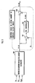
- One conventional fuel cell power supply device incorporates a control arrangement shown in FIG. 3 of the accompanying drawings for determining a target amount of generated electric energy (Ifc_CMD) for a fuel cell on a vehicle.
- a requested-amount-of-electric-energy calculator 100 determines a requested amount of generated electric energy (Ifc_CAL) required by the fuel cell depending on the amount of depression (Ap) of the accelerator pedal, the vehicle speed (Nm) of the vehicle, and the consumed amount of electric energy (Pload) used by electric accessories other than the electric motor.
- a subtractor 101 calculates the difference between the actual amount of generated electric energy (Ifc) and the requested amount of generated electric energy (Ifc_CAL).
- the calculated difference is processed according to a PID control process by a PID controller 102, which produces a corrective quantity (Ifc_AMD).
- An adder 103 adds the corrective quantity (Ifc_AMD) to the requested amount of generated electric energy (Ifc_CAL), thus calculating a target amount of generated electric energy (Ifc_CMD).
- the supply of reactive gases to the fuel gas is controlled such that the reactive gases are supplied to the fuel cell in an amount depending on the target amount of generated electric energy (Ifc_CMD).
- the control arrangement shown in FIG. 3 for calculating the target amount of generated electric energy (Ifc_CMD) and controlling the amount of the reactive gases supplied to the fuel cell in an amount depending on the target amount of generated electric energy (Ifc_CMD) suffers the following problems:
- the PID controller 102 and the adder 103 perform a corrective action to prevent the target amount of generated electric energy (Ifc_CMD) from increasing.
- the transient response of the fuel cell is lowered, causing the fuel cell to suffer a lack of the reactive gases.
- a fuel cell power supply device comprising a fuel cell, reactive gas supply means for supplying reactive gases to the fuel cell, supplied-amount regulating means for regulating an amount of reactive gases supplied from the reactive gas supply means to the fuel cell, target-amount-of-generated-electric-energy determining means for determining a target amount of electric energy generated by the fuel cell depending on a requested electric energy of a load which is connected to the fuel cell, and gas supply control means for performing a gas supply control process to enable the supplied-amount regulating means to regulate the amount of reactive gases supplied from the reactive gas supply means to the fuel cell in order to supply an amount of reactive gases greater than the amount of reactive gases depending on the target amount of electric energy.
- the fuel cell power supply device includes actual-amount-of-electric-energy detecting means for detecting an actual amount of electric energy generated by the fuel cell, and the gas supply control means comprises means for comparing the target amount of electric energy and the actual amount of electric energy with each other, and performing the gas supply control process using the actual amount of electric energy as the target amount of electric energy if actual amount of electric energy is greater than the target amount of electric energy.
- the gas supply control means basically performs the gas supply control process to supply the target amount of reactive gases set depending on the target amount of generated electric energy determined by the target-amount-of-generated-electric-energy determining means, thus preventing the reactive gases from being supplied excessively or insufficiently.
- the requested electric energy changes due to the increased load, and the actual amount of electric energy generated by the fuel cell may become greater than the target amount of generated electric energy due to a time lag until the target amount of generated electric energy is changed by the target-amount-of-generated-electric-energy determining means depending on the change in the requested electric energy.
- the gas supply control means compares the target amount of electric energy determined by the target-amount-of-generated-electric-energy determining means and the actual amount of electric energy with each other while the gas supply control process is being carried out, and performs the gas supply control process using the actual amount of electric energy as the target amount of electric energy if actual amount of electric energy is greater than the target amount of electric energy.
- the amount of reactive gases supplied to the fuel cell is thus quickly increased, preventing the fuel cell from running short of reactive gases.
- the fuel cell power supply device also has electric storage means connected parallel to the fuel cell, for being charged with an output current from the fuel cell and discharged when the amount of electric energy generated by the fuel cell is smaller than the requested electric energy.
- the target amount of electric energy determined by the target-amount-of-generated-electric-energy determining means is reduced, thus reducing the reactive gases supplied to the fuel cell according to the gas supply control process.
- the output voltage of the fuel cell is increased.
- the electric storage means is connected parallel to the fuel cell, in order to increase the output voltage of the fuel cell, it is necessary to supply a charging current from the fuel cell to the electric storage means to charge the electric storage means for thereby increasing the output voltage of the fuel cell. While the target amount of generated electric energy is being reduced, therefore, it is necessary to supply electric energy to the electric storage means as well as the load. If the target amount of generated electric energy is determined depending on the requested electric energy of the load, the amount of reactive gases supplied to the fuel cell may tend to suffer a shortage commensurate with the charging current supplied to the electric storage means.
- the gas supply control process is performed using the actual amount of generated electric energy as the target amount of generated electric energy, so that the gas supply control means can prevent the fuel cell from running short of reactive gases.
- a fuel cell power supply device according to the present invention will be described below with reference to FIGS. 1 and 2.
- a fuel cell power supply device 1 is mounted on a vehicle and functions as a propulsive power supply for the vehicle.
- the fuel cell power supply device 1 is a hybrid fuel cell power supply device comprising a fuel cell stack 2 for outputting an electric current based on an electrochemical reaction between reactive gases of hydrogen and air, and an electric double layer capacitor 3 (corresponding to an electric storage means according to the present invention, hereinafter referred to as "capacitor 3") connected parallel to the fuel cell stack 2.
- the output electric energy produced by the fuel cell power supply device 1 is controlled by a controller 4 which comprises a microcomputer, a memory, and other components.
- the controller 4 has as its functions a driver control unit 9, a power supply management control unit 14, and a fuel cell control unit 16.
- the output electric energy produced by the fuel cell power supply device 1 is supplied to a motor driver 5, an air-conditioning unit 6, and a 12-V vehicle-mounted load 8 through a DC/DC converter.
- the motor driver 5 control currents flowing through the armatures of an electric motor 10 depending on a torque command value (TRQ_CMD) outputted from the driver control unit 9 of the controller 4.
- TRQ_CMD torque command value
- the drive power generated by the electric motor 10 is transferred to drive wheels 12 through a transmission 11.
- the driver control unit 9 outputs a signal indicative of a motor-requested electric energy (PD_REQ) which is required by the motor driver 5 based on the amount of depression (Ap) of an accelerator pedal 13 and the rotational speed (Nm) of the electric motor 10, to the power supply management control unit 14 of the controller 4.
- PD_REQ motor-requested electric energy
- the power supply management control unit 14 is supplied with detected signals of a load current (I_load) and a load voltage (V_load) which are detected by a load sensor 15 in order to recognize the electric energy consumed by electric accessories other than the electric motor 10.
- the power supply management control unit 14 takes into account an allowable output current (Ifc_LMT) outputted from the fuel cell control unit 16 and indicative of an upper limit for the current that can be supplied from the fuel cell stack 2 and various states (an output voltage and a temperature) of capacitor cells (not shown) of the capacitor 3, determines a target amount of generated electric energy (Ifc_CMD) which is a target value for a current outputted from the fuel cell stack 2 depending on the sum of the motor-requested electric energy (PD_REQ) and the electric energy consumed by the electric accessories other than the electric motor 10, and outputs a signal indicative of the target amount of generated electric energy (Ifc_CMD) to the fuel cell control unit 16.
- the power supply management control unit 14 also outputs a signal indicative of an output limit electric energy (PLD) representing an upper limit for the electric energy that can be supplied from the fuel cell stack 2, to the driver control unit 9.
- PLD output limit electric energy
- the fuel cell control unit 16 is supplied with detected signals outputted from a reactive gas sensor 20 and indicating a pressure (Pgas), a flow rate (Qgas), and a temperature (Tgas) of reactive gases (hydrogen and air) supplied to the fuel cell stack 2, and detected signals indicative of states (Vcell_indiv) of individual fuel cells that make up the fuel cell stack 2.
- the fuel cell control unit 16 determines the allowable output current (Ifc_LMT) in view of the state of the fuel cell stack 2 as recognized from these detected signals.
- the driver control unit 9 outputs a signal indicative of a torque command (TRQ_CMD) to the motor driver 5 so as not to exceed the output limit electric energy (PLD) indicated by the power supply management control unit 14.
- TRQ_CMD a torque command
- PLD output limit electric energy
- the motor driver 5 controls the armature currents of the electric motor 10 to cause the electric motor 10 to generate a torque depending on the torque command (TRQ_CMD).
- the fuel cell control unit 16 outputs a signal indicative of a target amount of reactive gases (CMP_CMD) supplied to the fuel cell stack 2 to a reactive gas supply device 21 (corresponding to a reactive gas supply means according to the present invention) so that the fuel cell stack 2 will output a current for the target amount of generated electric energy (Ifc_CMD).
- a reactive gas supply device 21 Based on the target amount of reactive gases (CMP_CMD), the reactive gas supply device 21 supplies air and hydrogen at a rate depending on the target amount of generated electric energy (Ifc_CMD).
- the reactive gas supply device 21 has a mechanism (not shown) for regulating the rate at which the reactive gases are supplied.
- This regulating mechanism corresponds to a supplied-amount regulating means according to the present invention.
- Hydrogen supplied from the reactive gas supply device 21 is supplied to hydrogen electrodes of the fuel cell stack 2 through an ejector (not shown) and a humidifier (not shown), and reacts electrically and chemically with oxygen in air supplied to air electrodes of the fuel cell stack 2, producing water which is discharged through a discharge valve 22.
- the opening of the discharge valve 22 is controlled by a control signal (VLV_CMD) supplied from the fuel cell control unit 16 in order to keep the pressure in the fuel cell stack 2 at a constant gradient depending on the pressures of the supplied air and hydrogen.
- the fuel cell stack 2 has a water-cooled cooling unit (not shown).
- the fuel cell control unit 16 controls the rate and temperature of cooling water supplied to the water-cooled cooling unit depending on the temperature of the cooling water supplied to the water-cooled cooling unit and the temperature of the cooling water discharged from the water-cooled cooling unit.
- the fuel cell power supply device 1 also has a fuel cell sensor 30 (including the function of an actual-amount-of-electric-energy detecting means according to the present invention) for detecting an output current (Ifc) and an output voltage (Vfc) from the fuel cell stack 2, and a capacitor sensor 31 for detecting a current (Icap) charged into and discharged from the capacitor 3 and a voltage (Vcap) across the capacitor 3. Detected signals from the fuel cell sensor 30 and the capacitor sensor 31 are supplied to the power supply management control unit 14.
- the driver control unit 9 has a requested electric energy calculator 50 which calculates a motor-requested electric energy (PD_REQ) based on the amount of depression (Ap) of the accelerator pedal 13 (see FIG. 1) and the rotational speed (Nm) of. the electric motor 10 (see FIG. 1) which is outputted from the motor driver 5, and outputs a signal indicative of the calculated motor-requested electric energy (PD_REQ) to the power supply management control unit 14.
- PD_REQ motor-requested electric energy
- the power supply management control unit 14 has a requested-amount-of-generated-electric-energy calculator 51 (corresponding to a target-amount-of-generated-electric-energy determining means according to the present invention) which recognizes an electric energy consumed by the electric accessories other than the electric motor 10 from the detected signals of the load current (I_load) and the load voltage (V_load) which are detected by the load sensor 15, and adds the recognized electric energy and the motor-requested electric energy (PD_REQ) to each other, thus calculating a total electric energy required to energize the electric motor 10 and the electric accessories.
- a requested-amount-of-generated-electric-energy calculator 51 corresponding to a target-amount-of-generated-electric-energy determining means according to the present invention
- the requested-amount-of-generated-electric-energy calculator 51 applies the total electric energy to electric energy/current conversion map data, stored in a memory, representative of the correlation between the output electric power and output current of the fuel cell stack 2, and converts the total electric energy into a current, as the requested amount of generated electric energy (Ifc_CAL) (corresponding to a target amount of generated electric energy according to the present invention), which is a total amount of current required to energize the electric motor 10 and the electric accessories.
- Ifc_CAL the requested amount of generated electric energy
- the power supply management control unit 14 also has an actual-amount-of-generated-electric-energy calculator 52 which calculates an actual amount of generated electric energy (Ifc_s) which is an amount of current actually outputted from the fuel cell stack 2, based on the output current (Ifc) of the fuel cell stack 2 (see FIG. 1) which is detected by the fuel cell sensor 30.
- Ifc_s an actual amount of generated electric energy
- the power supply management control unit 14 also has a target selector 53 which compares the requested amount of generated electric energy (Ifc_CAL) and the actual amount of generated electric energy (Ifc_s) with each other. If the requested amount of generated electric energy (Ifc_CAL) is equal to or greater than the actual amount of generated electric energy (Ifc_s), then the target selector 53 regards the requested amount of generated electric energy (lfc_CAL) as the target amount of generated electric energy (Ifc_CMD) for the fuel cell stack 2, and outputs a signal indicative of the target amount of generated electric energy (Ifc_CMD) to the fuel cell control unit 16.
- a target selector 53 which compares the requested amount of generated electric energy (Ifc_CAL) and the actual amount of generated electric energy (Ifc_s) with each other. If the requested amount of generated electric energy (Ifc_CAL) is equal to or greater than the actual amount of generated electric energy (Ifc_s), then the target selector 53 regards the requested amount of generated electric energy (lfc_CAL) as the target amount of
- the fuel cell control unit 16 has a target-amount-of-supplied-gases calculator 54 which applies the target amount of generated electric energy (Ifc_CMD) to generated-amount/consumed-amount map data, stored in a memory, representing the correlation between the amount of electric energy (amount of current) generated by the fuel cell stack 2 and the amount of reactive gases consumed by the fuel cell stack 2, and calculates an amount of reactive gases consumed by the fuel cell stack 2 which is required to achieve the target amount of generated electric energy (lfc_CMD).
- Ifc_CMD target amount of generated electric energy
- the target-amount-of-supplied-gases calculator 54 determines a target amount of reactive gases (CMP_CMD) with a margin given to the amount of reactive gases consumed by the fuel cell stack 2 when the target amount of generated electric energy (Ifc_CMD) is obtained, depending on the target amount of generated electric energy (Ifc_CMD), and outputs a signal indicative of the determined target amount of reactive gases (CMP_CMD) to the reactive gas supply device 21.
- a gas supply control process is performed to control the operation of the reactive gas supply device 21 in order to supply the reactive gases in the target amount of reactive gases (CMP_CMD) to the fuel cell stack 2.
- the target-amount-of-supplied-gases calculator 54 and the target selector 53 jointly make up a gas supply control means according to the present invention.
- the fuel cell control unit 16 also has an allowable output value calculator 55 which calculates an allowable output current (Ifc_LMT) and outputs a signal indicative of the calculated allowable output current (Ifc_LMT) to the power supply management control unit 14.
- the power supply management control unit 14 has a motor-drive-electric-energy-limit calculator 56 which determines an output limit electric energy (PLD) such that the amount of electric energy generated by the fuel cell stack 2 does not exceed the allowable output current (Ifc_LMT), and outputs a signal indicative of the output limit electric energy (PLD) to the driver control unit 9.
- PLD output limit electric energy
- the driver control unit 9 has a motor-drive-electric-energy calculator 57 which compares the motor-requested electric energy (PD_REQ) calculated by the requested electric energy calculator 50 and the output limit electric energy (PLD) with each other, and determines a torque command value (TRQ_CMD) outputted to the motor driver 5 such that the electric energy consumed by the electric motor 10 does not exceed the output limit electric energy (PLD).
- PD_REQ motor-requested electric energy
- PLD output limit electric energy
- the requested amount of generated electric energy (Ifc_CAL) calculated by the requested-amount-of-generated-electric-energy calculator 51 is directly used as the target amount of generated electric energy (Ifc_CMD) for the fuel cell stack 2, and the signal indicative of the target amount of generated electric energy (Ifc_CMD) is outputted to the fuel cell control unit 16 to perform the gas supply control process to determine a torque command value (TRQ_CMD) to be outputted from the drive control unit 9 to the motor driver 5 such that the electric energy consumed by the electric motor 10 does not exceed the output limit electric energy (PLD).
- TRQ_CMD torque command value
- the actual amount of electric energy generated by the fuel cell stack 2 is usually kept equal to or smaller than the requested amount of generated electric energy (Ifc_CAL) calculated by the requested-amount-of-generated-electric-energy calculator 51 according to the gas supply control process.
- the electric energy consumed by the electric accessories such as the air-conditioning unit 6 (see FIG. 1), other than the electric motor 10 is not managed by the power supply management control unit 14.
- the detected values of the load voltage (Vload) and the load current (Iload) change, requiring a certain time to be taken until the requested amount of generated electric energy (Ifc_CAL) calculated by the requested-amount-of-generated-electric-energy calculator 51 is changed.
- CMP_CMD target amount of reactive gases
- the motor-requested electric energy (PD_REQ) When the electric energy consumed by the electric motor 10 is lowered, the motor-requested electric energy (PD_REQ) is reduced. When the electric energy consumed by the electric accessories is lowered, the load voltage (Vload) and the load current (Iload) are reduced. Therefore, the requested amount of generated electric energy (Ifc_CAL) calculated by the requested-amount-of-generated-electric-energy calculator 51 is reduced. However, since the output voltage of the fuel cell stack 2 becomes higher as the amount of electric energy generated thereby (the output current thereof) is reduced. In order to reduce the amount of electric energy generated by the fuel cell stack 2, it is necessary to charge the capacitor 3 connected parallel to the fuel cell stack 2 to increase the output voltage of the capacitor 3.
- the target selector 53 regards the actual amount of generated electric energy (Ifc_s) as the target amount of generated electric energy (Ifc_CMD) for the fuel cell control unit 16.
- the target selector 53 regards the actual amount of generated electric energy (Ifc_s) as the target amount of generated electric energy (Ifc_CMD) for the fuel cell control unit 16.
- the target-amount-of-supplied-gases calculator 54 determines the target amount of reactive gases (CMP_CMD) to given a margin to the consumed amount of air depending on the actual amount of generated electric energy (Ifc_s). Therefore, the amount of reactive gases supplied from the reactive gas supply device 21 to the fuel cell stack 2 is prevented from suffering a shortage, thus protecting the fuel cell stack 2 from a lack of the reactive gases.
- the output current of the fuel cell stack 2 is used as the amount of generated electric energy.
- the output electric energy of the fuel cell stack 2 may be used as the amount of generated electric energy.
- the requested-amount-of-generated-electric-energy calculator 51 is not required to convert the electric energy into a current.
- an electric energy which is the sum of the motor-requested electric energy (PD_REQ) and the consumed electric energy of the electric accessories which is calculated from the load current (I_load) and the load voltage (V_load) which are detected by the load sensor 15 may be used as a requested amount of generated electric energy, and an electric energy which is calculated by multiplying the output current (Ifc) from the fuel cell sensor 30 by the output voltage (Vfc) from the fuel cell sensor 30 may be used as an actual amount of generated electric energy, and these requested and actual amounts of generated electric energy may be compared with each other.
- the fuel cell control unit 16 may convert a target amount of generated electric energy into an output current of the fuel cell stack 2 for thereby determining a target amount of reactive gases (CMP_CMD).
- the electric double layer capacitor is used as the electric storage means.
- the principles of the present invention are also applicable to capacitors and batteries of other types.
- a power supply management control unit 14 has a requested-amount-of-generated-electric-energy calculator 51 for calculating a requested amount of electric energy (Ifc_CAL) generated by a fuel cell stack 2 depending on a requested electric energy of an electric motor and an electric load other than the electric motor, an actual-amount-of-generated-electric-energy calculator 52 for calculating an actual amount of electric energy (Ifc_s) generated by the fuel cell stack 2 based on a current (Ifc) detected by a fuel cell sensor 30, and a target selector 53 for comparing the requested amount of electric energy (Ifc_CAL) and the actual amount of electric energy (Ifc_s) with each other, regarding the requested amount of electric energy (Ifc_CAL) as a target amount of generated electric energy (Ifc_REQ) for a fuel cell control unit 16 if the requested amount of electric energy (Ifc_CAL) is equal to or greater than the actual amount of electric energy (Ifc_s), and regarding the actual amount of electric energy (Ifc_s) as target amount of generated electric energy (
Landscapes
- Engineering & Computer Science (AREA)
- Life Sciences & Earth Sciences (AREA)
- Sustainable Development (AREA)
- Sustainable Energy (AREA)
- Chemical Kinetics & Catalysis (AREA)
- Chemical & Material Sciences (AREA)
- Electrochemistry (AREA)
- General Chemical & Material Sciences (AREA)
- Manufacturing & Machinery (AREA)
- Transportation (AREA)
- Mechanical Engineering (AREA)
- Power Engineering (AREA)
- Fuel Cell (AREA)
- Electric Propulsion And Braking For Vehicles (AREA)
Applications Claiming Priority (4)
| Application Number | Priority Date | Filing Date | Title |
|---|---|---|---|
| JP2001139934 | 2001-05-10 | ||
| JP2001139934 | 2001-05-10 | ||
| JP2002132000A JP4308479B2 (ja) | 2001-05-10 | 2002-05-07 | 燃料電池電源装置 |
| JP2002132000 | 2002-05-07 |
Publications (2)
| Publication Number | Publication Date |
|---|---|
| EP1256992A2 true EP1256992A2 (de) | 2002-11-13 |
| EP1256992A3 EP1256992A3 (de) | 2007-01-17 |
Family
ID=26614884
Family Applications (1)
| Application Number | Title | Priority Date | Filing Date |
|---|---|---|---|
| EP02010624A Withdrawn EP1256992A3 (de) | 2001-05-10 | 2002-05-10 | Brennstoffzellen-Stromversorgungseinrichtung |
Country Status (3)
| Country | Link |
|---|---|
| US (1) | US6875531B2 (de) |
| EP (1) | EP1256992A3 (de) |
| JP (1) | JP4308479B2 (de) |
Cited By (7)
| Publication number | Priority date | Publication date | Assignee | Title |
|---|---|---|---|---|
| WO2004027911A1 (en) * | 2002-09-23 | 2004-04-01 | Hydrogenics Corporation | A fuel cell system and method of operating the same |
| WO2004027907A3 (en) * | 2002-09-23 | 2004-06-24 | Hydrogenics Corp | System and method for process gas stream delivery and regulation in a fuel cell system using down spool control |
| EP1560285A1 (de) * | 2004-01-30 | 2005-08-03 | SFC Smart Fuel Cell AG | Verfahren zur Steuerung der Brennstoffzufuhr bei Brennstoffzellensystemen |
| WO2004027906A3 (en) * | 2002-09-23 | 2006-04-20 | Hydrogenics Corp | System and method for process gas stream delivery and regulation using open loop and closed loop control |
| WO2008116586A3 (de) * | 2007-03-23 | 2008-11-13 | Forschungszentrum Juelich Gmbh | Brennstoffzellensystem und verfahren zur regelung eines brennstoffzellensystems |
| CN101237058B (zh) * | 2006-09-29 | 2010-04-07 | 通用汽车环球科技运作公司 | 使用空气流量反馈延迟管理燃料电池功率增加的方法 |
| CN101293485B (zh) * | 2007-04-27 | 2011-01-26 | 杰生自动技术有限公司 | 一种交通工具外接电器电力管理方式及其装置 |
Families Citing this family (6)
| Publication number | Priority date | Publication date | Assignee | Title |
|---|---|---|---|---|
| JP3928154B2 (ja) * | 2001-05-29 | 2007-06-13 | 本田技研工業株式会社 | 燃料電池電源装置 |
| US7842428B2 (en) * | 2004-05-28 | 2010-11-30 | Idatech, Llc | Consumption-based fuel cell monitoring and control |
| JP2006310217A (ja) * | 2005-05-02 | 2006-11-09 | Toyota Motor Corp | 燃料電池システム |
| JP4404129B2 (ja) * | 2007-10-22 | 2010-01-27 | トヨタ自動車株式会社 | 燃料電池の出力制御装置 |
| JP5983197B2 (ja) * | 2012-08-31 | 2016-08-31 | マツダ株式会社 | 車両用電源装置およびその制御方法 |
| KR101550976B1 (ko) * | 2013-10-11 | 2015-09-08 | 현대자동차주식회사 | 연료 전지 차량의 공기 공급 제어 방법 |
Family Cites Families (9)
| Publication number | Priority date | Publication date | Assignee | Title |
|---|---|---|---|---|
| JPS6345763A (ja) * | 1986-08-12 | 1988-02-26 | Fuji Electric Co Ltd | 燃料電池発電プラントの運転制御装置 |
| JPH06275296A (ja) * | 1993-03-24 | 1994-09-30 | Fuji Electric Co Ltd | 燃料電池発電装置 |
| JP3687991B2 (ja) * | 1994-02-24 | 2005-08-24 | 株式会社エクォス・リサーチ | ハイブリッド電源装置 |
| JP4049833B2 (ja) * | 1996-07-26 | 2008-02-20 | トヨタ自動車株式会社 | 電源装置および電気自動車 |
| JP4031555B2 (ja) * | 1997-05-23 | 2008-01-09 | トヨタ自動車株式会社 | ガス供給装置 |
| US6387556B1 (en) * | 1997-11-20 | 2002-05-14 | Avista Laboratories, Inc. | Fuel cell power systems and methods of controlling a fuel cell power system |
| JP2000251911A (ja) * | 1999-03-03 | 2000-09-14 | Nissan Motor Co Ltd | 燃料電池発電システム |
| JP3730592B2 (ja) * | 2001-06-06 | 2006-01-05 | 本田技研工業株式会社 | 燃料電池自動車の制御装置 |
| JP3679070B2 (ja) * | 2001-06-22 | 2005-08-03 | 本田技研工業株式会社 | 燃料電池自動車の制御装置 |
-
2002
- 2002-05-07 JP JP2002132000A patent/JP4308479B2/ja not_active Expired - Fee Related
- 2002-05-10 EP EP02010624A patent/EP1256992A3/de not_active Withdrawn
- 2002-05-10 US US10/143,292 patent/US6875531B2/en not_active Expired - Lifetime
Cited By (7)
| Publication number | Priority date | Publication date | Assignee | Title |
|---|---|---|---|---|
| WO2004027911A1 (en) * | 2002-09-23 | 2004-04-01 | Hydrogenics Corporation | A fuel cell system and method of operating the same |
| WO2004027907A3 (en) * | 2002-09-23 | 2004-06-24 | Hydrogenics Corp | System and method for process gas stream delivery and regulation in a fuel cell system using down spool control |
| WO2004027906A3 (en) * | 2002-09-23 | 2006-04-20 | Hydrogenics Corp | System and method for process gas stream delivery and regulation using open loop and closed loop control |
| EP1560285A1 (de) * | 2004-01-30 | 2005-08-03 | SFC Smart Fuel Cell AG | Verfahren zur Steuerung der Brennstoffzufuhr bei Brennstoffzellensystemen |
| CN101237058B (zh) * | 2006-09-29 | 2010-04-07 | 通用汽车环球科技运作公司 | 使用空气流量反馈延迟管理燃料电池功率增加的方法 |
| WO2008116586A3 (de) * | 2007-03-23 | 2008-11-13 | Forschungszentrum Juelich Gmbh | Brennstoffzellensystem und verfahren zur regelung eines brennstoffzellensystems |
| CN101293485B (zh) * | 2007-04-27 | 2011-01-26 | 杰生自动技术有限公司 | 一种交通工具外接电器电力管理方式及其装置 |
Also Published As
| Publication number | Publication date |
|---|---|
| EP1256992A3 (de) | 2007-01-17 |
| US6875531B2 (en) | 2005-04-05 |
| JP2003036873A (ja) | 2003-02-07 |
| US20020192518A1 (en) | 2002-12-19 |
| JP4308479B2 (ja) | 2009-08-05 |
Similar Documents
| Publication | Publication Date | Title |
|---|---|---|
| EP1270310B1 (de) | Regelvorrichtung für ein von Brennstoffzellen angetriebenes Fahrzeug | |
| EP2270910B1 (de) | Methode um einen Brennstoffzellefahrzeug und ein Brennstoffzellesystem zu steuern | |
| JP3662872B2 (ja) | 燃料電池電源装置 | |
| JP3719229B2 (ja) | 電源装置 | |
| US7485383B2 (en) | Fuel cell power supply | |
| CA2392212C (en) | Reactive gas supply regulating fuel cell power supply device | |
| JP3724365B2 (ja) | 燃料電池システムの制御装置及び方法 | |
| US6899968B2 (en) | Fuel cell power supply device | |
| US7318971B2 (en) | Fuel cell system utilizing control of operating current to adjust moisture content within fuel cell | |
| US6875531B2 (en) | Fuel cell power supply device | |
| US6691810B2 (en) | Apparatus for controlling fuel cell vehicle | |
| JP4180998B2 (ja) | 燃料電池発電システム | |
| EP1266789B1 (de) | Regelvorrichtung für ein von Brennstoffzellen angetriebenes Fahrzeug | |
| JP2006109650A (ja) | 車両用制御装置及び車両制御方法 | |
| JP4335303B2 (ja) | 燃料電池電源装置 |
Legal Events
| Date | Code | Title | Description |
|---|---|---|---|
| PUAI | Public reference made under article 153(3) epc to a published international application that has entered the european phase |
Free format text: ORIGINAL CODE: 0009012 |
|
| AK | Designated contracting states |
Kind code of ref document: A2 Designated state(s): AT BE CH CY DE DK ES FI FR GB GR IE IT LI LU MC NL PT SE TR |
|
| AX | Request for extension of the european patent |
Free format text: AL;LT;LV;MK;RO;SI |
|
| PUAL | Search report despatched |
Free format text: ORIGINAL CODE: 0009013 |
|
| AK | Designated contracting states |
Kind code of ref document: A3 Designated state(s): AT BE CH CY DE DK ES FI FR GB GR IE IT LI LU MC NL PT SE TR |
|
| AX | Request for extension of the european patent |
Extension state: AL LT LV MK RO SI |
|
| 17P | Request for examination filed |
Effective date: 20070122 |
|
| AKX | Designation fees paid |
Designated state(s): DE GB |
|
| 17Q | First examination report despatched |
Effective date: 20080623 |
|
| GRAP | Despatch of communication of intention to grant a patent |
Free format text: ORIGINAL CODE: EPIDOSNIGR1 |
|
| RIC1 | Information provided on ipc code assigned before grant |
Ipc: B60L 15/20 20060101AFI20141128BHEP Ipc: B60L 11/18 20060101ALI20141128BHEP Ipc: H01M 16/00 20060101ALI20141128BHEP Ipc: H01M 8/04 20060101ALI20141128BHEP |
|
| INTG | Intention to grant announced |
Effective date: 20141219 |
|
| RIN1 | Information on inventor provided before grant (corrected) |
Inventor name: AOYAGI, SATOSHI Inventor name: HASEGAWA, YUSUKE Inventor name: SAEKI, HIBIKI Inventor name: KOTAKA, KAZUO |
|
| STAA | Information on the status of an ep patent application or granted ep patent |
Free format text: STATUS: THE APPLICATION IS DEEMED TO BE WITHDRAWN |
|
| 18D | Application deemed to be withdrawn |
Effective date: 20150430 |