EP1256473A1 - Cabriolet-Fahrzeug mit einem rückwärtigen Dachteil - Google Patents
Cabriolet-Fahrzeug mit einem rückwärtigen Dachteil Download PDFInfo
- Publication number
- EP1256473A1 EP1256473A1 EP02009910A EP02009910A EP1256473A1 EP 1256473 A1 EP1256473 A1 EP 1256473A1 EP 02009910 A EP02009910 A EP 02009910A EP 02009910 A EP02009910 A EP 02009910A EP 1256473 A1 EP1256473 A1 EP 1256473A1
- Authority
- EP
- European Patent Office
- Prior art keywords
- roof part
- roof
- vehicle according
- rear roof
- cabriolet vehicle
- Prior art date
- Legal status (The legal status is an assumption and is not a legal conclusion. Google has not performed a legal analysis and makes no representation as to the accuracy of the status listed.)
- Granted
Links
- 238000011144 upstream manufacturing Methods 0.000 claims 1
- 101100498160 Mus musculus Dach1 gene Proteins 0.000 description 4
- 239000000969 carrier Substances 0.000 description 4
- 229920003023 plastic Polymers 0.000 description 3
- 239000004033 plastic Substances 0.000 description 3
- 239000002184 metal Substances 0.000 description 2
- PZASAAIJIFDWSB-CKPDSHCKSA-N 8-[(1S)-1-[8-(trifluoromethyl)-7-[4-(trifluoromethyl)cyclohexyl]oxynaphthalen-2-yl]ethyl]-8-azabicyclo[3.2.1]octane-3-carboxylic acid Chemical compound FC(F)(F)C=1C2=CC([C@@H](N3C4CCC3CC(C4)C(O)=O)C)=CC=C2C=CC=1OC1CCC(C(F)(F)F)CC1 PZASAAIJIFDWSB-CKPDSHCKSA-N 0.000 description 1
- 206010041953 Staring Diseases 0.000 description 1
- 238000005253 cladding Methods 0.000 description 1
- 238000010276 construction Methods 0.000 description 1
- 230000001419 dependent effect Effects 0.000 description 1
- 229920002635 polyurethane Polymers 0.000 description 1
- 239000004814 polyurethane Substances 0.000 description 1
- 239000007787 solid Substances 0.000 description 1
- 229920001187 thermosetting polymer Polymers 0.000 description 1
Images




Classifications
-
- B—PERFORMING OPERATIONS; TRANSPORTING
- B60—VEHICLES IN GENERAL
- B60J—WINDOWS, WINDSCREENS, NON-FIXED ROOFS, DOORS, OR SIMILAR DEVICES FOR VEHICLES; REMOVABLE EXTERNAL PROTECTIVE COVERINGS SPECIALLY ADAPTED FOR VEHICLES
- B60J7/00—Non-fixed roofs; Roofs with movable panels, e.g. rotary sunroofs
- B60J7/08—Non-fixed roofs; Roofs with movable panels, e.g. rotary sunroofs of non-sliding type, i.e. movable or removable roofs or panels, e.g. let-down tops or roofs capable of being easily detached or of assuming a collapsed or inoperative position
- B60J7/12—Non-fixed roofs; Roofs with movable panels, e.g. rotary sunroofs of non-sliding type, i.e. movable or removable roofs or panels, e.g. let-down tops or roofs capable of being easily detached or of assuming a collapsed or inoperative position foldable; Tensioning mechanisms therefor, e.g. struts
- B60J7/1226—Soft tops for convertible vehicles
- B60J7/1265—Soft tops for convertible vehicles characterised by kinematic movements, e.g. using parallelogram linkages
- B60J7/1282—Soft tops for convertible vehicles characterised by kinematic movements, e.g. using parallelogram linkages foldable against a main arch before attaining fully open mode
-
- B—PERFORMING OPERATIONS; TRANSPORTING
- B60—VEHICLES IN GENERAL
- B60J—WINDOWS, WINDSCREENS, NON-FIXED ROOFS, DOORS, OR SIMILAR DEVICES FOR VEHICLES; REMOVABLE EXTERNAL PROTECTIVE COVERINGS SPECIALLY ADAPTED FOR VEHICLES
- B60J7/00—Non-fixed roofs; Roofs with movable panels, e.g. rotary sunroofs
- B60J7/08—Non-fixed roofs; Roofs with movable panels, e.g. rotary sunroofs of non-sliding type, i.e. movable or removable roofs or panels, e.g. let-down tops or roofs capable of being easily detached or of assuming a collapsed or inoperative position
- B60J7/12—Non-fixed roofs; Roofs with movable panels, e.g. rotary sunroofs of non-sliding type, i.e. movable or removable roofs or panels, e.g. let-down tops or roofs capable of being easily detached or of assuming a collapsed or inoperative position foldable; Tensioning mechanisms therefor, e.g. struts
- B60J7/1226—Soft tops for convertible vehicles
- B60J7/1265—Soft tops for convertible vehicles characterised by kinematic movements, e.g. using parallelogram linkages
- B60J7/1278—Soft tops for convertible vehicles characterised by kinematic movements, e.g. using parallelogram linkages the complete top rotating around a single main axis on the vehicle body
-
- B—PERFORMING OPERATIONS; TRANSPORTING
- B60—VEHICLES IN GENERAL
- B60J—WINDOWS, WINDSCREENS, NON-FIXED ROOFS, DOORS, OR SIMILAR DEVICES FOR VEHICLES; REMOVABLE EXTERNAL PROTECTIVE COVERINGS SPECIALLY ADAPTED FOR VEHICLES
- B60J7/00—Non-fixed roofs; Roofs with movable panels, e.g. rotary sunroofs
- B60J7/185—Locking arrangements
- B60J7/19—Locking arrangements for rigid panels
- B60J7/196—Locking arrangements for rigid panels for locking or interconnecting rigid roof panels to each other
Definitions
- the invention relates to a convertible vehicle with one in the rear vehicle area depositable roof according to the preamble of claim 1.
- a convertible vehicle is known, the one has rear roof part, which in its rear area is pivotally hinged to the body.
- the roof part is about this rear pivot axis between an in essential horizontal open position and an inclined closed position movable.
- the roof part cannot be completely relocated, but by connecting its rear area to the swivel axis, which is in the area of the window sill line is the rear one Roof part not under the fixed parapet line even when the roof is open sunk. It stands out visually disruptive.
- to open a trunk still allow the stored roof part even in the opposite Direction can be swiveled, which increases the design effort elevated.
- the invention is based on the problem of a convertible vehicle with a to create a rear roof part that opens to the roof by a rear Axle can be swiveled into the bodywork and thereby the above disadvantage avoids.
- the invention solves this problem by means of a convertible vehicle with the features of claim 1. To advantageous embodiments is dependent on the Claims 2 to 8 referenced.
- the convertible vehicle according to the invention is a storage of the roof possible completely below the fixed parapet line. Even if more Roof parts can be stored above the rear roof part, these can be pivoted in with the rear roof part in such a way that when open Roof the body line is not disturbed by protruding roof parts. Due to the spacing of the roof parts from the swivel axis, there is also a large lever arm reached, so that even with manual actuation only a small one Force must be applied to apply a torque with which the roof from the open position to a raised position of the rear Roof part is spent. Thus it can be a cheap and simple as well as easy to use operating construction.
- the trunk is also almost completely preserved, especially then when the outrigger that connects the rear roof part with the rear side Connect swivel axis, are assigned to the vehicle sides and thus in Edge area, for example, arranged behind existing cladding can be.
- the swivel axis is in the outermost rear area, this is also the result Trunk not affected. Due to the lowered position of the swivel axis it is also possible to open a trunk lid without restrictions. At the same time, the focus of the vehicle is by lowering the Swivel axis lowered, which has a positive influence on driving behavior.
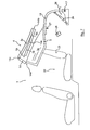
- the convertible vehicle 1 shown in Fig. 1 has an overall movable Roof 2, which has a rigid rear roof part 3 and one in the direction of travel F subsequent flexible roof part 4 comprises.
- the here rigid rear roof part 3 with the rear window 3a is connected via a body-side, transversely extending horizontal pivot axis 17 pivotally held.
- the roof part 3 consists of the rear window 3a Plastic or light metal.
- the horizontal pivot axis 17 is in the closed Position of the roof 2 (Fig. 1) below and clearly to the rear of the rear roof part 3.
- the pivot axis 17 is via two lateral arms 18,19, which serve as swivel arms and rigidly fixed to the rear roof part 3 are connected to it.
- the arms 18, 19 are the outside of the vehicle assigned and for example via hydraulic cylinders or other drive elements 20, 21 can be actuated. Also a purely manual operation or assistance from gas pressure cylinders in manual operation is possible. Due to the lateral position of the arms 18, 19, these can approximately be arranged behind panels and therefore the trunk volume unrestricted to let.
- the rear roof part 3 can also essentially only be formed by a panoramic rear window.
- the roof 2 can essentially overall be flexible and in its rear Area, for example, only have a bracket on the boom 18.19 is held.
- the roof 2 can be of a uniform Cover (not shown) overlapped to ensure a uniform look.
- the convertible vehicle 1 has a rear row of seats equipped, which is fundamentally not mandatory.
- the convertible vehicle according to the invention can also be a two-seater.
- the roof covering of the flexible roof area 4 is between the vehicle edge Frame supports 5.6 and stretched over beams 7.8.
- the carriers 7, 8 are arranged in the longitudinal direction of the vehicle and connect them in the embodiment, the rigid rear roof part 3 with an upper area of the front windshield frame 9.
- Carrier 7,8 next to the edge frame supports 5,6 a different number of additional carriers 7, 8 can also be provided.
- In particular can also be a longitudinally extending beam in the vertical vehicle longitudinal median plane lie.
- cross connectors 10, 11 are between the longitudinal beams 7,8 provided. However, this is not mandatory. On the other hand, you can also such cross connector between the longitudinal beams 7,8 and the edge Frame supports 5.6 may be provided.
- the cross beams 10, 11 run just below the top of the side members 7,8, causing them to become do not draw in the stretched cover.
- the longitudinal beams 7,8 and the edge frame profiles 5,6 are via a cross member 16 on the front, which bears against the windshield frame 9 serves, connected to each other.
- the longitudinal carriers 7, 8 are each in the exemplary embodiment three joints 12a, 12b, 12c and 13a, 13b, 13c in their longitudinal course in four sections 7a, 7b, 7c, 7d; 8a, 8b, 8c, 8d divided.
- the outer frame supports too 5; 6 are each in a corresponding manner with three joints 14a, 14b, 14c and 15a, 15b, 15c provided over their longitudinal course and into the corresponding sections 5a, 5b, 5c, 5d; 6a, 6b, 6c, 6d divided.
- the flexible roof area is foldable around these joints, as shown in FIGS. 2 and 3. A different number of joints is also possible.
- the position of the joints 12a, 13a, 14a or 12b, 13b, 14b, 12c, 13c, 14c of the respective carrier 7, 8 or frame supports 5,6 is coordinated so that each with a folding movement all joints 12a, 13a, 14a, 15a or 12b, 13b, 14b assigned to one another, 15b or 12c, 13c, 14c, 15c can be folded in at the same time.
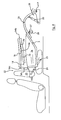
- the convertible vehicle 1 shown in the embodiment includes the further a rear row of seats 22, the seat backs 23 from the rear extreme position (Fig. 5) are displaceable in the direction of travel F.
- This is used for example a swivel arm 24, which is about a body-fixed joint 25 is pivotable and the seat back 23 is shifted forward. Also a guided tour or the like is possible.
- the extreme rear position of the Seat backs 23 represent the normal use position of the rear row of seats 22 represents.
- the front cross member 16 is first removed from the windshield frame 9 lifted off.
- the joints 12a, 13a, 14a, 15a; 12b, 13b, 14b, 15b buckled, so that they previously butted there Sections 5a, 5b, 5c and 6a, 6b, 6c of the side frame supports 5,6 and 7a, 7b, 7c and 8a, 8b, 8c of the side members 7,8 against each other are angled (Fig. 6).
- the sections 5a, 5b, 6a, 6b, 7a, 7b, 8a, 8b are then swung back almost 180 ° and on the sections 5c, 6c, 7c, 8c filed (Fig. 2).
- the joint 12c, 13c, 14c, 15c buckled so that the areas 5c, 6c, 7c, 8c pass through one vertical position can be stored to the rear, the front sections 5a, 5b, 6a lying on the areas 5c, 6c, 7c, 8c , 6b, 7a, 7b, 8a, 8b in a parallel position to the sections 5c, 6c, 7c, 8c remain.
- the joint 12d, 13d, 14d, 15d finally becomes buckled, making the flexible area overall like a roller roof 4 is placed on the rigid roof part 3 (Fig. 7).
- the section 5d, 6d, 7d, 8d stands almost vertically, while the other sections essentially Lie parallel on the rear window 3a.
- the backrest is first 23 of the rear row of seats 22 from the rear extreme position (Fig. 7) in the extreme front position (Fig. 8), so that the area 22 of the rear Row of seats can be used as storage space for the open roof 2.
- the roof opening can, in order to achieve an overall cost-effective solution, done entirely manually. Also a partial manual opening, for example of the flexible area 4, and a mechanically supported or driven Opening the rigid rear area 3 of the roof 2 is possible.
- the side members 7,8 can, like the side members 5,6, for example, consist of one Plastic, especially a mechanically heavy-duty plastic, such as such as a thermoset, such as polyurethane.
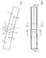
- the beams 7,8 and the lateral frame supports 5,6 are essentially the same formed and each include a solid profile, for example a triangular profile (see Fig. 9, Fig. 10).
- joint areas 12a, 13a, 14a, 15a, 12b, 13b, 14b, 15b, 12c, 13c, 14c, 15c have the side members 7,8 and the outer frame supports 5,6 each one with the roof closed, a positive engagement of the parts securing training on that described in Figures 9 to 16 for the joint 12a and is provided with the corresponding reference numerals. Training is the same for the other joints mentioned.
- the carrier parts 7a, 7b, which abut each other at the joint 12a, are in the joint region each provided with connectors 30,31, the connectors have a particularly high hardness and wear resistance and are formed, for example, from a metal.
- Figure 9 shows a side view of parts 7a, 7b of the longitudinal beam 7, which in the direction of arrows 32,33 can open against each other at the top.
- the flexible roof or the flexible roof area 4 can be one so-called inner headliner, so that neither the carrier 7.8 nor the cross members 10,11 or the frame supports 5,6 from the interior are visible from.
Landscapes
- Engineering & Computer Science (AREA)
- Mechanical Engineering (AREA)
- Body Structure For Vehicles (AREA)
- Seal Device For Vehicle (AREA)
Abstract
Description
- Fig. 1
- eine schematische, perspektivische Ansicht eines erfindungsgemäßen Cabriolet-Fahrzeugs bei geschlossenem Dach,
- Fig. 2
- eine ähnliche Ansicht wie Fig. 1 bei teilweise geöffnetem flexiblem Dachteil,
- Fig. 3
- eine ähnliche Ansicht wie Fig. 2 während der weiteren Öffnung des flexiblen Dachteils,
- Fig. 4
- eine ähnliche Ansicht wie Fig. 3 bei vollständig geöffnetem Dach,
- Fig. 5
- eine schematische Seitenansicht des Cabriolet-Fahrzeugs bei vollständig geschlossenem Dach,
- Fig. 6
- eine ähnliche Ansicht wie Fig. 5 während der Öffnung des flexiblen Dachteils,
- Fig. 7
- eine ähnliche Ansicht wie Fig. 6 bei vollständiger Öffnung des flexiblen Dachteils und noch geschlossener Stellung eines starren hinteren Dachteils,
- Fig. 8
- eine ähnliche Ansicht wie Fig. 7 bei vollständig geöffnetem Dach,
- Fig. 9
- eine Detailansicht eines Längsträgers von der Seite gesehen,
- Fig. 10
- eine Draufsicht auf den Längsträger nach Fig. 9,
- Fig. 11
- eine perspektivische Ansicht des Längsträgers in seinem Gelenkbereich,
- Fig. 12
- eine Seitenansicht des Längsträgers bei aufgeschwenkter Stellung der Teile gegeneinander,
- Fig. 13
- eine Seitenansicht der gegeneinander aufgeschwenkten Teile des Längsträgers,
- Fig. 14
- einen Schnitt entlang der Linie XIV-XIV in Fig. 10,
- Fig. 15
- einen Schnitt entlang der Linie XV-XV in Fig. 10,
- Fig. 16
- einen Schnitt entlang der Linie XVI-XVI in Fig. 9.
Claims (8)
- Cabriolet-Fahrzeug (1) mit einem im rückwärtigen Fahrzeugbereich ablegbaren Dach (2), das ein rückwärtiges, eine Heckscheibe (3a) umfassendes Dachteil (3) enthält, gekennzeichnet durch eine karosserieseitige, quer verlaufende Horizontalschwenkachse (17), die heckwärts und unterhalb der Erstreckung des hinteren Dachteils (3) angeordnet ist und mit der das hintere Dachteil (3) über sich zwischen diesem und der Achse (17) erstreckenden Auslegern (18;19) derart verbunden ist, daß es um die genannte Achse (17) schwenkbar ist.
- Cabriolet-Fahrzeug nach Anspruch 1, dadurch gekennzeichnet, daß die Ausleger (18;19) als zwei den Fahrzeugseiten zugeordnete Schwenkarme ausgebildet sind.
- Cabriolet-Fahrzeug nach Anspruch 1, dadurch gekennzeichnet, daß das hintere Dachteil (3) in Offenstellung des Daches (2) in einer im wesentlichen horizontalen Lage, in der die Heckscheibe (3a) aufwärts weist, gehalten ist.
- Cabriolet-Fahrzeug nach einem der Ansprüche 1 bis 3, dadurch gekennzeichnet, daß dem rückwärtigen Dachteil (3) in Fahrtrichtung (F) zumindest ein weiteres Dachteil (4) vorgeordnet ist.
- Cabriolet-Fahrzeug nach Anspruch 4, dadurch gekennzeichnet, daß das oder die vor dem rückwärtigen Dachteil befindliche(n) weitere(n) Dachteil(e) (4) in Offenstellung des Daches auf dem rückwärtigen Dachteil (3) ablegbar ist oder sind.
- Cabriolet-Fahrzeug nach Anspruch 5, dadurch gekennzeichnet, daß als vorderes Dachteil (4) ein im wesentlichen flexibles, von in Fahrzeuglängsrichtung erstreckten Trägern (7;8) untergriffenes Faltdachteil vorgesehen ist.
- Cabriolet-Fahrzeug nach Anspruch 6, dadurch gekennzeichnet, daß die Längsträger (7;8) des vorderen Dachteils an mehreren Gelenken (12a,12b,12c, 12d;13a,13b,13c,13d) quer zur Fahrzeuglängsachse einfaltbar sind.
- Cabriolet-Fahrzeug nach einem der Ansprüche 1 bis 7, dadurch gekennzeichnet, daß das oder die vordere(n) Dachteil(e) (4) und das rückwärtige Dachteil (3) von einer gemeinsamen Außenhülle übergriffen sind.
Applications Claiming Priority (2)
| Application Number | Priority Date | Filing Date | Title |
|---|---|---|---|
| DE10123229 | 2001-05-12 | ||
| DE10123229A DE10123229B4 (de) | 2001-05-12 | 2001-05-12 | Cabriolet-Fahrzeug mit einem rückwärtigen Dachteil |
Publications (3)
| Publication Number | Publication Date |
|---|---|
| EP1256473A1 true EP1256473A1 (de) | 2002-11-13 |
| EP1256473B1 EP1256473B1 (de) | 2007-08-22 |
| EP1256473B8 EP1256473B8 (de) | 2008-03-19 |
Family
ID=7684612
Family Applications (1)
| Application Number | Title | Priority Date | Filing Date |
|---|---|---|---|
| EP02009910A Expired - Lifetime EP1256473B8 (de) | 2001-05-12 | 2002-05-03 | Cabriolet-Fahrzeug mit einem rückwärtigen Dachteil |
Country Status (3)
| Country | Link |
|---|---|
| EP (1) | EP1256473B8 (de) |
| AT (1) | ATE370855T1 (de) |
| DE (1) | DE10123229B4 (de) |
Citations (4)
| Publication number | Priority date | Publication date | Assignee | Title |
|---|---|---|---|---|
| US5033789A (en) * | 1989-03-31 | 1991-07-23 | Aisin Seiki Kabushiki Kaisha | Convertible car body structure |
| DE4326329C1 (de) * | 1992-02-05 | 1994-09-29 | Webasto Karosseriesysteme | Fahrzeugdach |
| EP0764553A1 (de) * | 1995-09-22 | 1997-03-26 | PININFARINA S.p.A. | Cabriolet-Fahrzeug mit trennbarem und schwenkbarem, festem Dach |
| DE19737259A1 (de) * | 1997-08-27 | 1999-03-04 | Ruediger Hoffmann | Hardtop-Fahrzeug |
Family Cites Families (4)
| Publication number | Priority date | Publication date | Assignee | Title |
|---|---|---|---|---|
| US5620226A (en) * | 1995-12-07 | 1997-04-15 | Dura Convertible Systems, Inc. | Simplified automated top operator |
| DE19749194A1 (de) * | 1997-11-07 | 1999-05-12 | Bayerische Motoren Werke Ag | Personenkraftwagen mit einem auf eine Heckklappe verfahrenbaren Dachteil |
| DE19936252C5 (de) * | 1999-07-31 | 2008-01-10 | Magna Car Top Systems Gmbh | Hardtop-Fahrzeugdach |
| DE19939954B4 (de) * | 1999-08-23 | 2007-07-19 | Edscha Cabrio-Dachsysteme Gmbh | Faltschiebedachanordnung |
-
2001
- 2001-05-12 DE DE10123229A patent/DE10123229B4/de not_active Expired - Fee Related
-
2002
- 2002-05-03 AT AT02009910T patent/ATE370855T1/de not_active IP Right Cessation
- 2002-05-03 EP EP02009910A patent/EP1256473B8/de not_active Expired - Lifetime
Patent Citations (4)
| Publication number | Priority date | Publication date | Assignee | Title |
|---|---|---|---|---|
| US5033789A (en) * | 1989-03-31 | 1991-07-23 | Aisin Seiki Kabushiki Kaisha | Convertible car body structure |
| DE4326329C1 (de) * | 1992-02-05 | 1994-09-29 | Webasto Karosseriesysteme | Fahrzeugdach |
| EP0764553A1 (de) * | 1995-09-22 | 1997-03-26 | PININFARINA S.p.A. | Cabriolet-Fahrzeug mit trennbarem und schwenkbarem, festem Dach |
| DE19737259A1 (de) * | 1997-08-27 | 1999-03-04 | Ruediger Hoffmann | Hardtop-Fahrzeug |
Also Published As
| Publication number | Publication date |
|---|---|
| EP1256473B1 (de) | 2007-08-22 |
| EP1256473B8 (de) | 2008-03-19 |
| DE10123229A1 (de) | 2002-11-21 |
| ATE370855T1 (de) | 2007-09-15 |
| DE10123229B4 (de) | 2006-06-14 |
Similar Documents
| Publication | Publication Date | Title |
|---|---|---|
| DE4038074C1 (en) | Roof for cabriolet vehicle - has roof pivoting on two support link rods hinged on lateral supports | |
| DE10063152B4 (de) | Klappdachwagen | |
| DE3925150C2 (de) | ||
| DE10212573B4 (de) | Versenkbares Dach für Personenkraftfahrzeuge, insbesondere Hartdach für zwei- und mehrsitzige Cabriolets, Roadster o. dgl. | |
| EP1112879A2 (de) | Umwandelbares Fahrzeugdach | |
| EP1554145B1 (de) | Cabriolet-fahrzeug | |
| EP1092579A1 (de) | Versenkbares Kraftfahrzeugverdeck sowie Kraftfahrzeug mit diesem Verdeck | |
| DE10152944A1 (de) | Verdeck für ein Cabriolet-Fahrzeug | |
| DE19913033A1 (de) | Personenkraftwagen mit einem Stoff-Falt-Verdeck und mit einer starren Heckscheibe | |
| DE19846006A1 (de) | Starres Klappverdeck für Kraftfahrzeuge | |
| DE19939954B4 (de) | Faltschiebedachanordnung | |
| EP0943474B1 (de) | Versenkbares Festdach für Cabrio-Fahrzeuge | |
| DE10348726B4 (de) | Personenkraftwagen mit Aufbauöffnungen | |
| EP1331122B1 (de) | Kraftfahrzeug mit versenkbarem Hardtop | |
| DE19704570A1 (de) | Kraftwagen mit einem zu öffnenden Verdeck | |
| DE102006052852A1 (de) | Konvertierbare Fahrzeugkarosserie | |
| DE102004021576A1 (de) | Cabriolet-Fahrzeug | |
| EP1897718B1 (de) | Faltverdeck | |
| DE10258052A1 (de) | Verstellbares Fahrzeugdach für Cabriolet-Fahrzeuge | |
| EP1260394B1 (de) | Cabriolet-Fahrzeug mit zumindest einem flexiblen Dachbereich | |
| DE102004018606B4 (de) | Dachstruktur für ein zu öffnendes starres Kraftfahrzeugdach | |
| DE102004029148B3 (de) | Hardtop-Fahrzeugdach mit mindestens zwei Dachteilen | |
| EP1256474B1 (de) | Cabriolet-Fahrzeug mit einem zumindest bereichsweise flexiblen Dach | |
| DE10120359C2 (de) | Fahrzeug mit einem zu öffnenden Verdeck | |
| EP2004432A1 (de) | Hardtop-klappverdeck für einen offenen kraftwagen |
Legal Events
| Date | Code | Title | Description |
|---|---|---|---|
| PUAI | Public reference made under article 153(3) epc to a published international application that has entered the european phase |
Free format text: ORIGINAL CODE: 0009012 |
|
| AK | Designated contracting states |
Kind code of ref document: A1 Designated state(s): AT BE CH CY DE DK ES FI FR GB GR IE IT LI LU MC NL PT SE TR |
|
| AX | Request for extension of the european patent |
Free format text: AL;LT;LV;MK;RO;SI |
|
| 17P | Request for examination filed |
Effective date: 20030312 |
|
| AKX | Designation fees paid |
Designated state(s): AT BE CH CY DE DK ES FI FR GB GR IE IT LI LU MC NL PT SE TR |
|
| RBV | Designated contracting states (corrected) |
Designated state(s): AT BE CH CY DK ES FI FR GB GR IE IT LI LU MC NL PT SE TR |
|
| REG | Reference to a national code |
Ref country code: DE Ref legal event code: 8566 |
|
| GRAP | Despatch of communication of intention to grant a patent |
Free format text: ORIGINAL CODE: EPIDOSNIGR1 |
|
| GRAS | Grant fee paid |
Free format text: ORIGINAL CODE: EPIDOSNIGR3 |
|
| GRAA | (expected) grant |
Free format text: ORIGINAL CODE: 0009210 |
|
| AK | Designated contracting states |
Kind code of ref document: B1 Designated state(s): AT BE CH CY DK ES FI FR GB GR IE IT LI LU MC NL PT SE TR |
|
| REG | Reference to a national code |
Ref country code: GB Ref legal event code: FG4D Free format text: NOT ENGLISH |
|
| REG | Reference to a national code |
Ref country code: CH Ref legal event code: EP |
|
| REG | Reference to a national code |
Ref country code: IE Ref legal event code: FG4D Free format text: LANGUAGE OF EP DOCUMENT: GERMAN |
|
| GBT | Gb: translation of ep patent filed (gb section 77(6)(a)/1977) |
Effective date: 20071126 |
|
| PG25 | Lapsed in a contracting state [announced via postgrant information from national office to epo] |
Ref country code: NL Free format text: LAPSE BECAUSE OF FAILURE TO SUBMIT A TRANSLATION OF THE DESCRIPTION OR TO PAY THE FEE WITHIN THE PRESCRIBED TIME-LIMIT Effective date: 20070822 Ref country code: FI Free format text: LAPSE BECAUSE OF FAILURE TO SUBMIT A TRANSLATION OF THE DESCRIPTION OR TO PAY THE FEE WITHIN THE PRESCRIBED TIME-LIMIT Effective date: 20070822 Ref country code: ES Free format text: LAPSE BECAUSE OF FAILURE TO SUBMIT A TRANSLATION OF THE DESCRIPTION OR TO PAY THE FEE WITHIN THE PRESCRIBED TIME-LIMIT Effective date: 20071203 |
|
| NLV1 | Nl: lapsed or annulled due to failure to fulfill the requirements of art. 29p and 29m of the patents act | ||
| ET | Fr: translation filed | ||
| REG | Reference to a national code |
Ref country code: IE Ref legal event code: FD4D |
|
| PG25 | Lapsed in a contracting state [announced via postgrant information from national office to epo] |
Ref country code: GR Free format text: LAPSE BECAUSE OF FAILURE TO SUBMIT A TRANSLATION OF THE DESCRIPTION OR TO PAY THE FEE WITHIN THE PRESCRIBED TIME-LIMIT Effective date: 20071123 Ref country code: DK Free format text: LAPSE BECAUSE OF FAILURE TO SUBMIT A TRANSLATION OF THE DESCRIPTION OR TO PAY THE FEE WITHIN THE PRESCRIBED TIME-LIMIT Effective date: 20070822 |
|
| PG25 | Lapsed in a contracting state [announced via postgrant information from national office to epo] |
Ref country code: PT Free format text: LAPSE BECAUSE OF FAILURE TO SUBMIT A TRANSLATION OF THE DESCRIPTION OR TO PAY THE FEE WITHIN THE PRESCRIBED TIME-LIMIT Effective date: 20080122 Ref country code: IE Free format text: LAPSE BECAUSE OF FAILURE TO SUBMIT A TRANSLATION OF THE DESCRIPTION OR TO PAY THE FEE WITHIN THE PRESCRIBED TIME-LIMIT Effective date: 20070822 |
|
| PLBE | No opposition filed within time limit |
Free format text: ORIGINAL CODE: 0009261 |
|
| STAA | Information on the status of an ep patent application or granted ep patent |
Free format text: STATUS: NO OPPOSITION FILED WITHIN TIME LIMIT |
|
| PG25 | Lapsed in a contracting state [announced via postgrant information from national office to epo] |
Ref country code: SE Free format text: LAPSE BECAUSE OF FAILURE TO SUBMIT A TRANSLATION OF THE DESCRIPTION OR TO PAY THE FEE WITHIN THE PRESCRIBED TIME-LIMIT Effective date: 20071122 |
|
| 26N | No opposition filed |
Effective date: 20080526 |
|
| BERE | Be: lapsed |
Owner name: WILHELM KARMANN G.M.B.H. Effective date: 20080531 |
|
| PG25 | Lapsed in a contracting state [announced via postgrant information from national office to epo] |
Ref country code: MC Free format text: LAPSE BECAUSE OF NON-PAYMENT OF DUE FEES Effective date: 20080531 |
|
| REG | Reference to a national code |
Ref country code: CH Ref legal event code: PL |
|
| PG25 | Lapsed in a contracting state [announced via postgrant information from national office to epo] |
Ref country code: LI Free format text: LAPSE BECAUSE OF NON-PAYMENT OF DUE FEES Effective date: 20080531 Ref country code: CH Free format text: LAPSE BECAUSE OF NON-PAYMENT OF DUE FEES Effective date: 20080531 |
|
| PG25 | Lapsed in a contracting state [announced via postgrant information from national office to epo] |
Ref country code: BE Free format text: LAPSE BECAUSE OF NON-PAYMENT OF DUE FEES Effective date: 20080531 |
|
| PG25 | Lapsed in a contracting state [announced via postgrant information from national office to epo] |
Ref country code: CY Free format text: LAPSE BECAUSE OF FAILURE TO SUBMIT A TRANSLATION OF THE DESCRIPTION OR TO PAY THE FEE WITHIN THE PRESCRIBED TIME-LIMIT Effective date: 20070822 |
|
| PG25 | Lapsed in a contracting state [announced via postgrant information from national office to epo] |
Ref country code: AT Free format text: LAPSE BECAUSE OF NON-PAYMENT OF DUE FEES Effective date: 20080503 |
|
| PGFP | Annual fee paid to national office [announced via postgrant information from national office to epo] |
Ref country code: GB Payment date: 20100329 Year of fee payment: 9 |
|
| PG25 | Lapsed in a contracting state [announced via postgrant information from national office to epo] |
Ref country code: LU Free format text: LAPSE BECAUSE OF NON-PAYMENT OF DUE FEES Effective date: 20080503 |
|
| PGFP | Annual fee paid to national office [announced via postgrant information from national office to epo] |
Ref country code: FR Payment date: 20100525 Year of fee payment: 9 |
|
| PG25 | Lapsed in a contracting state [announced via postgrant information from national office to epo] |
Ref country code: TR Free format text: LAPSE BECAUSE OF FAILURE TO SUBMIT A TRANSLATION OF THE DESCRIPTION OR TO PAY THE FEE WITHIN THE PRESCRIBED TIME-LIMIT Effective date: 20070822 |
|
| PGFP | Annual fee paid to national office [announced via postgrant information from national office to epo] |
Ref country code: IT Payment date: 20100515 Year of fee payment: 9 |
|
| GBPC | Gb: european patent ceased through non-payment of renewal fee |
Effective date: 20110503 |
|
| REG | Reference to a national code |
Ref country code: FR Ref legal event code: ST Effective date: 20120131 |
|
| PG25 | Lapsed in a contracting state [announced via postgrant information from national office to epo] |
Ref country code: IT Free format text: LAPSE BECAUSE OF NON-PAYMENT OF DUE FEES Effective date: 20110503 |
|
| PG25 | Lapsed in a contracting state [announced via postgrant information from national office to epo] |
Ref country code: FR Free format text: LAPSE BECAUSE OF NON-PAYMENT OF DUE FEES Effective date: 20110531 |
|
| PG25 | Lapsed in a contracting state [announced via postgrant information from national office to epo] |
Ref country code: GB Free format text: LAPSE BECAUSE OF NON-PAYMENT OF DUE FEES Effective date: 20110503 |