EP1256324A1 - Punktionskanüle - Google Patents
Punktionskanüle Download PDFInfo
- Publication number
- EP1256324A1 EP1256324A1 EP02008626A EP02008626A EP1256324A1 EP 1256324 A1 EP1256324 A1 EP 1256324A1 EP 02008626 A EP02008626 A EP 02008626A EP 02008626 A EP02008626 A EP 02008626A EP 1256324 A1 EP1256324 A1 EP 1256324A1
- Authority
- EP
- European Patent Office
- Prior art keywords
- cannula
- clamping
- steel
- cable
- recess
- Prior art date
- Legal status (The legal status is an assumption and is not a legal conclusion. Google has not performed a legal analysis and makes no representation as to the accuracy of the status listed.)
- Granted
Links
Images

Classifications
-
- A—HUMAN NECESSITIES
- A61—MEDICAL OR VETERINARY SCIENCE; HYGIENE
- A61B—DIAGNOSIS; SURGERY; IDENTIFICATION
- A61B17/00—Surgical instruments, devices or methods
- A61B17/34—Trocars; Puncturing needles
- A61B17/3401—Puncturing needles for the peridural or subarachnoid space or the plexus, e.g. for anaesthesia
Definitions
- the invention relates to a puncture cannula, in particular for the nerve stimulation, with a steel cannula attached to one Cannula attachment is attached, and one through an insertion channel running cable, the core of which is connected to the steel cannula is.
- a puncturing and catheterization device is known from EP 0 102 538 B1 known to puncture and catheterize Nerve strands is suitable.
- This device has a Steel cannula with a cannula hub provided at the distal end on, the steel cannula connected with a cable an electrical potential is applied to the steel cannula can be. If the steel cannula, the one bare Pointed, comes close to a nerve, occurs through electrical impulse by an appropriate stimulation device nerve stimulation with the cable corresponding reflexes of the patient. That way determine whether the cannula tip is sufficiently close to the desired one Nerve is brought up.
- the invention has for its object a puncture cannula to create that is easy to manufacture and a safe Contact between cable and puncture cannula guaranteed.
- the cannula hub contains a metallic clamping element, which one on the Steel cannula attacking the first clamping slot and one on the Cable core attacking second clamping slot.
- a metallic clamping element By Insert the clamping element into the cannula attachment Steel cannula and the cable wire automatically in the respective Clamping slot that tightly encloses them. This is done a simultaneous clamping of the two parts mentioned, without that the clamping of one part interferes with the other part becomes.
- the clamping element is a one-piece clamping element, whose clamping slots are arranged so that the first Clamping slot jams the steel cannula when the second clamping slot the cable is jammed. So have the clamping slots the same distance as steel cannula and cable wire and they will effective by moving the clamping element.
- a major advantage of the invention is that it is simple and safe installation.
- Steel cannulas and cables are passed through Moving the clamping element relative to each other and fixed also fixed in relation to the cannula hub. It is possible, perform the clamping before the steel cannula in the cannula attachment has been attached.
- the cable is shielded by the adhesive and additionally fixed.
- Another function of the adhesive is in that he has all the metallic parts on or in the cannula hub are present covered, so not the possibility there is that a person accidentally with one of the comes into contact with live parts.
- the second clamping slot has cutting edges, that penetrate insulation of the cable.
- cutting edges that penetrate insulation of the cable.
- the clamping slots in the plate are preferably one behind the other arranged, with a widened opening between them is provided.
- the two clamping slots are through the opening decoupled.
- the puncture cannula according to the invention is particularly suitable for the nerve stimulation, using different cannula techniques are applicable. For example, it is possible Anesthetic directly through the steel cannula inject or the steel cannula with a short catheter or Connect capillary. There is also the possibility of laying of a catheter through the one created by the steel cannula Puncture channel, either with or without guidewire.
- the clamping element can be designed such that it is for different diameters of steel cannulas and / or cable cores suitable is.
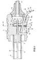
- the puncture cannula has an elongated hollow steel cannula 10 on, which is attached to a cannula hub 11 made of plastic is.
- the steel cannula 10 consists of a tube which is connected to a non-conductive coating 12 is provided, the (not shown) cannula tip exposed.
- the distal region 10a of the steel cannula 10 runs through a Cavity or a recess 14 of the cannula hub through and it ends in a cavity 15 through a hose connector 16 is complete. Extends from the hose connector 16 a tube 17 through which an anesthetic is supplied which can then be inserted through the steel cannula the patient's body is injected.
- the insertion channel 18 is open a part 18a of its length as a circumferentially closed bore trained and on another part 18b of its length as an open channel. Part 18b ends at an end wall 20 which forms a stop for the end of the cable 19.
- the cable 19 has a copper wire 21 and insulation 22 on.
- the insertion channel 18 runs under one acute angle to the longitudinal axis of the steel cannula 10 Steel cannula 10 and to the cable 19 runs a guide 23, in a clamping element 24 is movable.
- the clamping element 24 is made from an elastic plate 25 made of spring steel.
- the edges of the second clamping slot 27 are intersecting Edges that cut through the insulation 22 of the cable 19 and make a safe electrical contact to the cable core 21.
- the clamping slot 26 is delimited by wings 29,30 Bends 31 can be bent around to be different Adjust diameters of steel cannulas 10. On Wing 29 is shown in the bent state in Fig. 1.
- the clamping element 24 consists of a plate, but not must necessarily be flat.
- the record is in one linear guide 23 guided and can be between a clamping position and a release position.
Landscapes
- Health & Medical Sciences (AREA)
- Surgery (AREA)
- Life Sciences & Earth Sciences (AREA)
- Heart & Thoracic Surgery (AREA)
- Molecular Biology (AREA)
- Pathology (AREA)
- Engineering & Computer Science (AREA)
- Biomedical Technology (AREA)
- Anesthesiology (AREA)
- Medical Informatics (AREA)
- Nuclear Medicine, Radiotherapy & Molecular Imaging (AREA)
- Animal Behavior & Ethology (AREA)
- General Health & Medical Sciences (AREA)
- Public Health (AREA)
- Veterinary Medicine (AREA)
- Finger-Pressure Massage (AREA)
- Infusion, Injection, And Reservoir Apparatuses (AREA)
- Media Introduction/Drainage Providing Device (AREA)
Abstract
Description
- Fig. 1
- einen Längsschnitt durch eine Ausführungsform der Punktionskanüle,
- Fig. 2
- einen Schnitt entlang der Linie II-II von Fig. 1, und
- Fig. 3
- eine Ansicht aus Richtung des Pfeiles III von Fig. 1.
Claims (7)
- Punktionskanüle, insbesondere für die Nervenstimulation, mit einer Stahlkanüle (10), die an einem Kanülenansatz (11) befestigt ist, und einem durch einen Einführkanal (18) verlaufenden Kabel (19), dessen Ader (21) mit der Stahlkanüle (10) verbunden ist,
dadurch gekennzeichnet , dass der Kanülenansatz (11) ein metallisches Klemmelement (24) enthält, welches einen an der Stahlkanüle (10) angreifenden ersten Klemmschlitz (26) und einen an der Kabelader (21) angreifenden zweiten Klemmschlitz (27) aufweist. - Punktionskanüle nach Anspruch 1, dadurch gekennzeichnet, dass das Klemmelement (24) aus einer relativ zum Kanülenansatz (11) quer zur Längsrichtung der Stahlkanüle (10) verschiebbaren Platte (25) besteht, die in den Kanülenansatz (11) einschiebbar ist und im eingeschobenen Zustand gegen Herausziehen fixiert ist.
- Punktionskanüle nach Anspruch 1 oder 2, dadurch gekennzeichnet, dass der zweite Klemmschlitz (27) schneidende Kanten aufweist, die eine Isolierung (22) des Kabels (19) durchdringen.
- Punktionskanüle nach Anspruch 2, dadurch gekennzeichnet, dass die Klemmschlitze (26,27) in der Platte (25) hintereinander angeordnet sind, wobei zwischen ihnen eine verbreiterte Öffnung (28) vorgesehen ist.
- Punktionskanüle nach einem der Ansprüche 1-4, dadurch gekennzeichnet, dass der Einführkanal (18) mindestens auf einem Teil (18a) seiner Länge als Bohrung ausgebildet ist.
- Punktionskanüle nach einem der Ansprüche 1-5, dadurch gekennzeichnet, dass der Kanülenansatz (11) eine Ausnehmung (14) aufweist, durch die die Stahlkanüle (10) und ein Abschnitt des Kabels (19) hindurchgehen und dass in der Ausnehmung (14) eine Führung (23) zum Verschieben des Klemmelements (24) vorgesehen ist.
- Punktionskanüle nach Anspruch 6, dadurch gekennzeichnet, dass die Ausnehmung (14) mit einem Kleber (33) gefüllt ist, der auch das Klemmelement (24) bedeckt.
Applications Claiming Priority (2)
| Application Number | Priority Date | Filing Date | Title |
|---|---|---|---|
| DE20107778U DE20107778U1 (de) | 2001-05-08 | 2001-05-08 | Punktionskanüle |
| DE20107778U | 2001-05-08 |
Publications (2)
| Publication Number | Publication Date |
|---|---|
| EP1256324A1 true EP1256324A1 (de) | 2002-11-13 |
| EP1256324B1 EP1256324B1 (de) | 2004-03-10 |
Family
ID=7956635
Family Applications (1)
| Application Number | Title | Priority Date | Filing Date |
|---|---|---|---|
| EP02008626A Expired - Lifetime EP1256324B1 (de) | 2001-05-08 | 2002-04-17 | Punktionskanüle |
Country Status (4)
| Country | Link |
|---|---|
| US (1) | US6730083B2 (de) |
| EP (1) | EP1256324B1 (de) |
| JP (1) | JP4022428B2 (de) |
| DE (2) | DE20107778U1 (de) |
Cited By (1)
| Publication number | Priority date | Publication date | Assignee | Title |
|---|---|---|---|---|
| WO2025214836A1 (de) * | 2024-04-09 | 2025-10-16 | Aesculap Ag | Instrumentenschaft für ein elektrochirurgisches instrument und zugehöriges elektrochirurgisches instrument |
Families Citing this family (33)
| Publication number | Priority date | Publication date | Assignee | Title |
|---|---|---|---|---|
| US7386341B2 (en) * | 2000-03-13 | 2008-06-10 | Arrow International, Inc. | Instrument and method for delivery of anaesthetic drugs |
| US8611993B2 (en) * | 2000-03-13 | 2013-12-17 | Arrow International, Inc. | Pre-loaded lockable stimulating catheter for delivery of anaesthetic drugs |
| US7338514B2 (en) * | 2001-06-01 | 2008-03-04 | St. Jude Medical, Cardiology Division, Inc. | Closure devices, related delivery methods and tools, and related methods of use |
| US20070016226A1 (en) * | 2005-07-13 | 2007-01-18 | Bio Medic Data Systems, Inc. | Implanter |
| WO2008084778A1 (ja) | 2007-01-11 | 2008-07-17 | Nitto Denko Corporation | 高分子微多孔体の製造方法ならびに高分子微多孔体および分離膜 |
| CA2992612C (en) * | 2007-06-04 | 2020-03-24 | Avent, Inc. | Stimulating catheter |
| US8986283B2 (en) | 2011-05-18 | 2015-03-24 | Solo-Dex, Llc | Continuous anesthesia nerve conduction apparatus, system and method thereof |
| WO2012159000A2 (en) | 2011-05-18 | 2012-11-22 | Solodex Llc | Continuous anesthesia nerve conduction apparatus, system and method |
| US10471267B2 (en) | 2013-05-06 | 2019-11-12 | Medtronic, Inc. | Implantable cardioverter-defibrillator (ICD) system including substernal lead |
| US9717898B2 (en) | 2013-05-06 | 2017-08-01 | Medtronic, Inc. | Systems and methods for implanting a medical electrical lead |
| US9717923B2 (en) | 2013-05-06 | 2017-08-01 | Medtronic, Inc. | Implantable medical device system having implantable cardioverter-defibrillator (ICD) system and substernal leadless pacing device |
| US9220913B2 (en) | 2013-05-06 | 2015-12-29 | Medtronics, Inc. | Multi-mode implantable medical device |
| US20140330287A1 (en) | 2013-05-06 | 2014-11-06 | Medtronic, Inc. | Devices and techniques for anchoring an implantable medical device |
| US10556117B2 (en) | 2013-05-06 | 2020-02-11 | Medtronic, Inc. | Implantable cardioverter-defibrillator (ICD) system including substernal pacing lead |
| US10668270B2 (en) | 2013-05-06 | 2020-06-02 | Medtronic, Inc. | Substernal leadless electrical stimulation system |
| US10434307B2 (en) | 2013-10-15 | 2019-10-08 | Medtronic, Inc. | Methods and devices for subcutaneous lead implantation |
| US10792490B2 (en) | 2013-11-12 | 2020-10-06 | Medtronic, Inc. | Open channel implant tools and implant techniques utilizing such tools |
| US10531893B2 (en) | 2013-11-12 | 2020-01-14 | Medtronic, Inc. | Extravascular implant tools with open sheath and implant techniques utilizing such tools |
| US9867963B2 (en) * | 2014-06-17 | 2018-01-16 | Avent, Inc. | Needle hub for over-the-needle catheter |
| US10743960B2 (en) | 2014-09-04 | 2020-08-18 | AtaCor Medical, Inc. | Cardiac arrhythmia treatment devices and delivery |
| CA2959183C (en) | 2014-09-04 | 2023-10-10 | AtaCor Medical, Inc. | Receptacle for pacemaker lead |
| US10328268B2 (en) | 2014-09-04 | 2019-06-25 | AtaCor Medical, Inc. | Cardiac pacing |
| US9636505B2 (en) | 2014-11-24 | 2017-05-02 | AtaCor Medical, Inc. | Cardiac pacing sensing and control |
| US9636512B2 (en) | 2014-11-05 | 2017-05-02 | Medtronic, Inc. | Implantable cardioverter-defibrillator (ICD) system having multiple common polarity extravascular defibrillation electrodes |
| US11097109B2 (en) | 2014-11-24 | 2021-08-24 | AtaCor Medical, Inc. | Cardiac pacing sensing and control |
| US11083491B2 (en) | 2014-12-09 | 2021-08-10 | Medtronic, Inc. | Extravascular implant tools utilizing a bore-in mechanism and implant techniques using such tools |
| US10349978B2 (en) | 2014-12-18 | 2019-07-16 | Medtronic, Inc. | Open channel implant tool with additional lumen and implant techniques utilizing such tools |
| US10729456B2 (en) | 2014-12-18 | 2020-08-04 | Medtronic, Inc. | Systems and methods for deploying an implantable medical electrical lead |
| DE102016110379A1 (de) | 2016-06-06 | 2017-12-07 | Pajunk GmbH Medizintechnologie | Unipolar-Kanüle |
| DE102017201434A1 (de) * | 2017-01-30 | 2018-08-02 | Fresenius Medical Care Deutschland Gmbh | Kanülierautomat |
| CA3314271A1 (en) | 2019-05-29 | 2026-08-05 | AtaCor Medical, Inc. | Implantable electrical leads and associated delivery systems |
| US11666771B2 (en) | 2020-05-29 | 2023-06-06 | AtaCor Medical, Inc. | Implantable electrical leads and associated delivery systems |
| US12471896B2 (en) | 2021-11-24 | 2025-11-18 | AtaCor Medical, Inc. | Systems and methods for lead delivery |
Citations (3)
| Publication number | Priority date | Publication date | Assignee | Title |
|---|---|---|---|---|
| EP0102538B1 (de) | 1982-08-06 | 1986-08-06 | Sterimed Gesellschaft für medizinischen Bedarf mbH | Punktier- und Katheterisiervorrichtung für menschliche oder tierische Körper |
| EP0244017A1 (de) * | 1986-04-29 | 1987-11-04 | Koninklijke Philips Electronics N.V. | Elektrische Kontaktvorrichtung und Methode zu deren Herstellung |
| DE29803118U1 (de) * | 1998-02-21 | 1999-06-24 | Dotterweich, Hans, 79268 Bötzingen | Kanüle |
Family Cites Families (23)
| Publication number | Priority date | Publication date | Assignee | Title |
|---|---|---|---|---|
| US839268A (en) * | 1905-07-14 | 1906-12-25 | William R Burch | Support for surgical needles. |
| US853096A (en) * | 1906-06-16 | 1907-05-07 | Henry H Lewis | Depilatory instrument. |
| US3145261A (en) * | 1962-02-09 | 1964-08-18 | Amp Inc | Electrical connector for insulated wires |
| US3249103A (en) * | 1963-01-21 | 1966-05-03 | Charles F Woodhouse | Method and apparatus for measuring bioelectronic parameters |
| US3682162A (en) * | 1968-12-13 | 1972-08-08 | Wellcome Found | Combined electrode and hypodermic syringe needle |
| US3605072A (en) * | 1969-02-28 | 1971-09-14 | Minnesota Mining & Mfg | Solderless wire connector |
| US3957053A (en) | 1975-03-03 | 1976-05-18 | Yen Kong Woo | Detachably connected acupuncture needles |
| NZ193872A (en) * | 1979-06-29 | 1982-12-07 | Amp Inc | Electrical contact member and incorporated connector |
| DE3512482C2 (de) | 1985-04-04 | 1994-01-20 | Doron Dr Mehler | Katheterset |
| GB8618253D0 (en) * | 1986-07-25 | 1986-09-03 | Wallace Ltd H G | Intermittent administration of therapeutic substance |
| DE3782051T2 (de) | 1987-05-27 | 1993-03-25 | Siemens Ag | Verfahren zur elektrischen verbindung von leitungen und elektroden einer implantierbaren elektrodenleitung. |
| DE8715740U1 (de) | 1987-11-27 | 1988-01-14 | Krebs, Peter, Dr., 7730 Villingen-Schwenningen | Kombinationsnadel für die axilläre Plexus-Brachialis-Anästhesie |
| EP0444097B1 (de) | 1988-11-21 | 1994-11-09 | SZELES, Josef Constantin | Punktual-stimulations-nadel und punktual-stimulations-therapiegerät |
| US5046506A (en) * | 1990-02-09 | 1991-09-10 | Singer Medical Products, Inc. | Molded needle with adhesive |
| NL9200581A (nl) * | 1992-03-30 | 1993-10-18 | Akuaba B V | Implantatie-inrichting. |
| AU733337B2 (en) * | 1997-07-18 | 2001-05-10 | Gyrus Medical Limited | An electrosurgical instrument |
| US5976110A (en) | 1998-01-14 | 1999-11-02 | Duke University | Catheter system for administration of continuous peripheral nerve anesthetic |
| GB9800792D0 (en) * | 1998-01-16 | 1998-03-11 | Jones Michael H | Surgical needle holder |
| DE19828794C1 (de) | 1998-06-27 | 2000-02-24 | Heinrich Pajunk | Unipolar-Kanüle für die kontinuierliche Leitungsanästhesie |
| US6941171B2 (en) * | 1998-07-06 | 2005-09-06 | Advanced Bionics Corporation | Implantable stimulator methods for treatment of incontinence and pain |
| DE29820525U1 (de) | 1998-11-17 | 2000-04-06 | B. Braun Melsungen Ag, 34212 Melsungen | Katheterset für die Plexusanästhesie |
| US6456874B1 (en) * | 2000-03-13 | 2002-09-24 | Arrow International Inc. | Instrument for delivery of anaesthetic drug |
| US6533732B1 (en) * | 2000-10-17 | 2003-03-18 | William F. Urmey | Nerve stimulator needle guidance system |
-
2001
- 2001-05-08 DE DE20107778U patent/DE20107778U1/de not_active Expired - Lifetime
-
2002
- 2002-04-17 DE DE50200278T patent/DE50200278D1/de not_active Expired - Lifetime
- 2002-04-17 EP EP02008626A patent/EP1256324B1/de not_active Expired - Lifetime
- 2002-05-02 JP JP2002130618A patent/JP4022428B2/ja not_active Expired - Lifetime
- 2002-05-07 US US10/143,736 patent/US6730083B2/en not_active Expired - Lifetime
Patent Citations (3)
| Publication number | Priority date | Publication date | Assignee | Title |
|---|---|---|---|---|
| EP0102538B1 (de) | 1982-08-06 | 1986-08-06 | Sterimed Gesellschaft für medizinischen Bedarf mbH | Punktier- und Katheterisiervorrichtung für menschliche oder tierische Körper |
| EP0244017A1 (de) * | 1986-04-29 | 1987-11-04 | Koninklijke Philips Electronics N.V. | Elektrische Kontaktvorrichtung und Methode zu deren Herstellung |
| DE29803118U1 (de) * | 1998-02-21 | 1999-06-24 | Dotterweich, Hans, 79268 Bötzingen | Kanüle |
Cited By (1)
| Publication number | Priority date | Publication date | Assignee | Title |
|---|---|---|---|---|
| WO2025214836A1 (de) * | 2024-04-09 | 2025-10-16 | Aesculap Ag | Instrumentenschaft für ein elektrochirurgisches instrument und zugehöriges elektrochirurgisches instrument |
Also Published As
| Publication number | Publication date |
|---|---|
| DE20107778U1 (de) | 2001-10-11 |
| JP4022428B2 (ja) | 2007-12-19 |
| US6730083B2 (en) | 2004-05-04 |
| EP1256324B1 (de) | 2004-03-10 |
| US20020198557A1 (en) | 2002-12-26 |
| JP2002355291A (ja) | 2002-12-10 |
| DE50200278D1 (de) | 2004-04-15 |
Similar Documents
| Publication | Publication Date | Title |
|---|---|---|
| EP1256324B1 (de) | Punktionskanüle | |
| DE69509416T2 (de) | Stützkernband für kaltschrumpfbares rohr | |
| DE69824425T2 (de) | Verbindungssystem für stimulationsleitungen | |
| EP0646389B1 (de) | Anordnung zur Explantation einer Elektrodenvorrichtung | |
| DE3327585C2 (de) | ||
| DE29601310U1 (de) | Katheterbesteck mit EKG-Ableitungsmöglichkeit | |
| DE69117071T2 (de) | Elektrischer verbinder | |
| DE8803153U1 (de) | Kathetervorrichtung für die Plexusanästhesie | |
| DE2803395A1 (de) | Befestigungsvorrichtung fuer eine anordnung zum anlegen eines katheters | |
| DE8224292U1 (de) | Implantierbare leitung | |
| EP1002500A1 (de) | Katheterset für die Plexusanästhesie | |
| DE3244680A1 (de) | Vorrichtung zum zusammenhalten der teile eines gebrochenen knochens | |
| WO1999022807A1 (de) | Vorrichtung zum herausziehen eines ein längliches innenlumen aufweisenden gegenstandes aus seiner verankerung in einem körper | |
| DE2056602A1 (de) | Verfahren und Vorrichtung zum Befestigen von Verbindungstellen an Koaxialkabeln | |
| EP1180823B1 (de) | Kabelanschluss- oder -verbindungseinrichtung | |
| EP3463553B1 (de) | Unipolar-kanüle | |
| DE3536823A1 (de) | Elektrische elektrode und ein verfahren zum anbringen der elektrode an knochengewebe | |
| DE8209249U1 (de) | Verbindungselement, insbesondere für Fernmeldeleitungen | |
| DE2929233A1 (de) | Vorrichtung zum ausbilden eines gewebetunnels und/oder zum positionieren einer leitung in koerpergewebe | |
| DE4134004C2 (de) | Anschlußklemme mit unverlierbarer Schraube und Klemmleiste mit derartigen Klemmen | |
| EP0924799B1 (de) | Vorrichtung zum Verdrahten von Anschlussstellen von Komponenten elektrischer Geräte oder Anlagen | |
| DE29517060U1 (de) | Stimulationseinrichtung | |
| DE10022547C2 (de) | Kabelanschluß- oder -verbindungseinrichtung | |
| EP0966922B1 (de) | Unipolar-Kanüle für die kontinuerliche Leitungsanästhesie | |
| DE102006046181B4 (de) | Zugentlastungsvorrichtung für ein Glasfaserkabel |
Legal Events
| Date | Code | Title | Description |
|---|---|---|---|
| PUAI | Public reference made under article 153(3) epc to a published international application that has entered the european phase |
Free format text: ORIGINAL CODE: 0009012 |
|
| AK | Designated contracting states |
Kind code of ref document: A1 Designated state(s): AT BE CH CY DE DK ES FI FR GB GR IE IT LI LU MC NL PT SE TR |
|
| AX | Request for extension of the european patent |
Free format text: AL;LT;LV;MK;RO;SI |
|
| REG | Reference to a national code |
Ref country code: GB Ref legal event code: FG4D Free format text: NOT ENGLISH |
|
| 17P | Request for examination filed |
Effective date: 20030429 |
|
| GRAP | Despatch of communication of intention to grant a patent |
Free format text: ORIGINAL CODE: EPIDOSNIGR1 |
|
| AKX | Designation fees paid |
Designated state(s): DE FR GB IT |
|
| GRAS | Grant fee paid |
Free format text: ORIGINAL CODE: EPIDOSNIGR3 |
|
| GRAA | (expected) grant |
Free format text: ORIGINAL CODE: 0009210 |
|
| AK | Designated contracting states |
Kind code of ref document: B1 Designated state(s): DE FR GB IT |
|
| REG | Reference to a national code |
Ref country code: IE Ref legal event code: FG4D Free format text: GERMAN |
|
| REF | Corresponds to: |
Ref document number: 50200278 Country of ref document: DE Date of ref document: 20040415 Kind code of ref document: P |
|
| GBT | Gb: translation of ep patent filed (gb section 77(6)(a)/1977) |
Effective date: 20040615 |
|
| REG | Reference to a national code |
Ref country code: IE Ref legal event code: FD4D |
|
| ET | Fr: translation filed | ||
| PLBE | No opposition filed within time limit |
Free format text: ORIGINAL CODE: 0009261 |
|
| STAA | Information on the status of an ep patent application or granted ep patent |
Free format text: STATUS: NO OPPOSITION FILED WITHIN TIME LIMIT |
|
| 26N | No opposition filed |
Effective date: 20041213 |
|
| REG | Reference to a national code |
Ref country code: FR Ref legal event code: PLFP Year of fee payment: 15 |
|
| REG | Reference to a national code |
Ref country code: FR Ref legal event code: PLFP Year of fee payment: 16 |
|
| REG | Reference to a national code |
Ref country code: FR Ref legal event code: PLFP Year of fee payment: 17 |
|
| PGFP | Annual fee paid to national office [announced via postgrant information from national office to epo] |
Ref country code: IT Payment date: 20210430 Year of fee payment: 20 Ref country code: DE Payment date: 20210421 Year of fee payment: 20 Ref country code: FR Payment date: 20210421 Year of fee payment: 20 |
|
| PGFP | Annual fee paid to national office [announced via postgrant information from national office to epo] |
Ref country code: GB Payment date: 20210422 Year of fee payment: 20 |
|
| REG | Reference to a national code |
Ref country code: DE Ref legal event code: R071 Ref document number: 50200278 Country of ref document: DE |
|
| REG | Reference to a national code |
Ref country code: GB Ref legal event code: PE20 Expiry date: 20220416 |
|
| PG25 | Lapsed in a contracting state [announced via postgrant information from national office to epo] |
Ref country code: GB Free format text: LAPSE BECAUSE OF EXPIRATION OF PROTECTION Effective date: 20220416 |