EP1256293B1 - Chair, particularly office-chair - Google Patents
Chair, particularly office-chair Download PDFInfo
- Publication number
- EP1256293B1 EP1256293B1 EP02010377A EP02010377A EP1256293B1 EP 1256293 B1 EP1256293 B1 EP 1256293B1 EP 02010377 A EP02010377 A EP 02010377A EP 02010377 A EP02010377 A EP 02010377A EP 1256293 B1 EP1256293 B1 EP 1256293B1
- Authority
- EP
- European Patent Office
- Prior art keywords
- seat
- backrest
- support
- pivot point
- chair
- Prior art date
- Legal status (The legal status is an assumption and is not a legal conclusion. Google has not performed a legal analysis and makes no representation as to the accuracy of the status listed.)
- Expired - Lifetime
Links
Images

Classifications
-
- A—HUMAN NECESSITIES
- A47—FURNITURE; DOMESTIC ARTICLES OR APPLIANCES; COFFEE MILLS; SPICE MILLS; SUCTION CLEANERS IN GENERAL
- A47C—CHAIRS; SOFAS; BEDS
- A47C1/00—Chairs adapted for special purposes
- A47C1/02—Reclining or easy chairs
- A47C1/031—Reclining or easy chairs having coupled concurrently adjustable supporting parts
- A47C1/032—Reclining or easy chairs having coupled concurrently adjustable supporting parts the parts being movably-coupled seat and back-rest
- A47C1/03255—Reclining or easy chairs having coupled concurrently adjustable supporting parts the parts being movably-coupled seat and back-rest with a central column, e.g. rocking office chairs
-
- A—HUMAN NECESSITIES
- A47—FURNITURE; DOMESTIC ARTICLES OR APPLIANCES; COFFEE MILLS; SPICE MILLS; SUCTION CLEANERS IN GENERAL
- A47C—CHAIRS; SOFAS; BEDS
- A47C1/00—Chairs adapted for special purposes
- A47C1/02—Reclining or easy chairs
- A47C1/031—Reclining or easy chairs having coupled concurrently adjustable supporting parts
- A47C1/032—Reclining or easy chairs having coupled concurrently adjustable supporting parts the parts being movably-coupled seat and back-rest
- A47C1/03294—Reclining or easy chairs having coupled concurrently adjustable supporting parts the parts being movably-coupled seat and back-rest slidingly movable in the base frame, e.g. by rollers
Definitions
- the invention relates to a chair, in particular office chair, with a backrest articulated via a backrest support on a seat support and with a synchronously movable seat whose front area is connected via a sliding guide and the rear area via a seat link with the seat support.
- the synchronous mechanism serves to simultaneously change the position of the seat when adjusting the backrest.
- a chair or armchair with synchronously adjustable inclination of the backrest and seat known.
- the seat is raised by means of a hinged to the seat in the rear region on the one hand and the seat support handlebars with increasing inclination of the backrest, at the same time a rotatably connected on the one hand with the seat and on the other hand with the backrest arm drag lever pulls the seat back. Due to this lifting of the seat in the rear, the backrest facing area, the user can slide back when leaning the backrest on the seat.
- the seat surface should tilt backwards and downwards at least to the extent that the thrust force exerted on the seat or the seat surface by the user when leaning back is absorbed or absorbed.
- the invention is therefore based on the object of specifying a chair, in particular an office chair, with a particularly suitable and easily realizable synchronous mechanism.
- the invention is based on the consideration that in a chair or seating with adjustable seat and adjustable backrest, the adjustment of seat on the one hand and backrest on the other hand can be initially considered independently.
- the construction thus initially has two degrees of freedom.
- the adjustment of the backrest has only a single degree of freedom, if the articulation of the backrest on the seat support is realized in a simple manner via the backrest rigidly connected backrest support which is rotatably mounted on the seat support via a single axis of rotation.
- the seat may have more complex adjustment, but analogous to the adjustability of the backrest can still be assumed that the adjustment of the seat with a single degree of freedom can be described.
- the movement of the seat can in this case be both a translation and a tilting movement or a combination of different forms of movement.
- a coupling of the movements of the seat on the one hand and the backrest on the other hand should first ensure that each possible position of the backrest is associated with a position of the seat, whereby the entire construction is limited to one degree of freedom.
- the seat can be guided over an associated with this rigid axle in a provided in the backrest handle slot.
- the joint of the seat and the seat link upper pivot point is guided in a corresponding slot in the backrest handlebar.
- the seat link is expediently executed in the direction of the seat concave.
- the sliding guide provided in the front seating area can be realized by a slot provided in the seat carrier and by an axle guided therein, rigidly connected to the seat, or by a cylinder. Regardless, it is advantageously provided in the direction of the seat support obliquely down sliding slide.
- the inclined arrangement of effective as a length compensation element front sliding guide the seat not only undesirable lifting of the front edge of the seat when leaning back of the backrest is avoided, but rather achieved a lowering of the front edge of the seat when leaning back of the backrest. This reduction is pronounced, the more the inclination of the sliding guide deviates from the horizontal and runs in the direction of the vertical.
- the comfort is increased by the fact that the seat lowers when leaning back the backrest mainly in the rear area, while at the same time the leading edge of the Seat moved backwards and downwards. This gives the seat in the desired manner in the rear area a greater range of motion than in the front area.
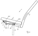
- the trained as an office chair chair 1 as shown in FIG. 1 comprises a fixedly connected to a stand 2 shown in dashed lines seat carrier 3.
- a backrest 5 is rotatably connected via a backrest support 4.
- the backrest 5 is tilted out of the rest position shown in FIG. 1 out in the reclined position or position shown in FIG. 2 backwards.
- the inclination of the backrest 5 is effected by a rotation about a pivot point D1.
- the backrest 5 fixedly connected backrest support 4 is connected to the seat support 3 via a rotation axis A, wherein the pivot point D1 is given substantially through the central axis of this axis of rotation A.
- a seat 6 is further articulated via a seat link 7, which is executed in the embodiment in the direction of the seat 6 convexly curved or bent.
- the seat link 7 is connected to the seat support 3 via a pivot D2 and with the seat 6 in its rear area, i. in which the backrest 5 facing rear seat half 6b rotatably connected via a rotary joint D3.
- the pivot points D2 and D3 are in turn realized by corresponding axes of rotation, via which the seat link 7 with the seat support 3 on the one hand and with the seat surface 6 on the other hand is rotatably connected.
- the seat 6 is connected via a sliding guide 8 with the seat support 3.
- the sliding guide 8 can in a manner not shown as a slot in the seat support 3 and guided therein, connected to the seat surface 6 rigid axis 9 or - as shown - run as a guided in the seat carrier 3 cylinder be. This is then rotatably connected to the seat 6 via the axis 9.
- the sliding guide 8 is inclined in the direction of the base 2.
- a sliding guide 10 provided in the backrest support 4.
- a slot 11 is expediently provided in the backrest support 4, in which the pivot point D3 between the seat surface 6 and the seat link 7 forming axis 12 is guided.
- a separate axis 12 may be provided in this area on the seat surface 6, which then does not coincide with the pivot point D3.
- the backrest 5 If the backrest 5 is brought by inclination to the rear in the position shown in Fig. 2, it is rotated by this inclination of the backrest support 4 in a clockwise direction and thus the seat link 7 moves together with the seat 6 down.
- the angle ⁇ between the seat link 7 and the vertical V increases from about 45 ° to 60 ° to about 90 °. In the end position, the seat link 7 is thus almost horizontal.
- the seat surface 6 Due to the inclination of the backrest 5, together with the pivot point D3, the seat surface 6 lowers in its rear region 6b. At the same time, the front edge 13 of the seat 6 moves backwards and downwards, with the length compensation required for this being effected by the front sliding guide 8. The consequent displacement of the front edge 13 of the seat surface 6 to the point 13 'shown in Fig. 1 is illustrated by the arrow length 14. This lowering of the front seat edge 13 is less than the lowering of the rear portion 6b of the seat surface 6 so that it is lowered overall and inclined clockwise.
Landscapes
- Health & Medical Sciences (AREA)
- Dentistry (AREA)
- General Health & Medical Sciences (AREA)
- Chairs For Special Purposes, Such As Reclining Chairs (AREA)
- Chairs Characterized By Structure (AREA)
- Hydrogenated Pyridines (AREA)
Abstract
Description
Die Erfindung bezieht sich auf einen Stuhl, insbesondere Bürostuhl, mit einer über einen Lehnenträger an einem Sitzträger angelenkten Rückenlehne und mit einer synchron hierzu bewegbaren Sitzfläche, deren vorderer Bereich über eine Schiebeführung und deren hinterer Bereich über einen Sitzlenker mit dem Sitzträger verbunden ist.The invention relates to a chair, in particular office chair, with a backrest articulated via a backrest support on a seat support and with a synchronously movable seat whose front area is connected via a sliding guide and the rear area via a seat link with the seat support.
Sitzmöbel und insbesondere Stühle, bei denen sich deren Sitzfläche und deren Rückenlehne synchron bewegen, sind mit verschiedenen Synchronmechaniken in Gebrauch. Die Synchronmechanik dient dazu, bei Verstellung der Rückenlehne gleichzeitig die Position der Sitzfläche zu verändern.Seating and in particular chairs in which move their seat and the backrest synchronously, are using various synchronous mechanisms in use. The synchronous mechanism serves to simultaneously change the position of the seat when adjusting the backrest.
So ist aus der DE 42 19 599 A1 ein Stuhl oder Sessel mit synchron verstellbarer Neigung von Rückenlehne und Sitz bekannt. Bei diesem Stuhl wird mittels eines an der Sitzfläche in deren hinteren Bereich einerseits und am Sitzträger andererseits angelenkten Sitzlenker mit zunehmender Neigung der Rückenlehne die Sitzfläche angehoben, wobei gleichzeitig ein einerseits mit der Sitzfläche und andererseits mit dem Lehnenlenker drehbar verbundener Schlepphebel die Sitzfläche nach hinten zieht. Aufgrund dieses Anhebens der Sitzfläche im hinteren, der Rükkenlehne zugewandten Bereich kann der Benutzer beim Zurücklehnen der Rükkenlehne auf der Sitzfläche nach vorne rutschen. Bei einer Synchronbewegung von Rückenlehne und Sitzfläche sollte sich die Sitzfläche jedoch zumindest soweit nach hinten und nach unten neigen, dass die vom Benutzer beim Zurücklehnen auf den Sitz oder die Sitzfläche ausgeübte Schubkraft aufgenommen bzw. aufgefangen wird.Thus, from DE 42 19 599 A1 a chair or armchair with synchronously adjustable inclination of the backrest and seat known. In this chair, the seat is raised by means of a hinged to the seat in the rear region on the one hand and the seat support handlebars with increasing inclination of the backrest, at the same time a rotatably connected on the one hand with the seat and on the other hand with the backrest arm drag lever pulls the seat back. Due to this lifting of the seat in the rear, the backrest facing area, the user can slide back when leaning the backrest on the seat. However, in the case of a synchronous movement of the backrest and seat surface, the seat surface should tilt backwards and downwards at least to the extent that the thrust force exerted on the seat or the seat surface by the user when leaning back is absorbed or absorbed.
Der Erfindung liegt daher die Aufgabe zugrunde, einen Stuhl, insbesondere einen Bürostuhl, mit besonders geeignetem und einfach realisierbarem Synchronmechanismus anzugeben.The invention is therefore based on the object of specifying a chair, in particular an office chair, with a particularly suitable and easily realizable synchronous mechanism.
Diese Aufgabe wird erfindungsgemäß gelöst durch die Merkmale des Anspruchs 1. Dazu ist einerseits der Abstand des den Sitzlenker mit der Sitzfläche verbindenden oberen Drehpunktes zur Rückenlehne kleiner als der Abstand des den Sitzlenker mit dem Sitzträger verbindenden unteren Drehpunktes zur Rückenlehne. Dadurch erfolgt mit zunehmender Neigung der Rückenlehne keine Anhebung, sondern vorteilhafterweise eine Absenkung der Sitzfläche. Andererseits ist zur Synchronisation zwischen der Bewegung der Rückenlehne und der Bewegung der Sitzfläche eine Schiebeführung der Sitzfläche im Lehnenlenker vorgesehen.This object is achieved by the features of
Die Erfindung geht dabei von der Überlegung aus, dass bei einem Stuhl oder Sitzmöbel mit verstellbarer Sitzfläche und verstellbarer Rückenlehne die Verstellmöglichkeiten von Sitzfläche einerseits und Rückenlehne andererseits zunächst unabhängig voneinander betrachtet werden können. Die Konstruktion weist somit zunächst zwei Freiheitsgrade auf. Die Verstellmöglichkeit der Rückenlehne weist dabei lediglich einen einzigen Freiheitsgrad auf, wenn die Anlenkung der Rükkenlehne am Sitzträger in einfacher Weise über den mit der Rückenlehne starr verbundenen Lehnenträger realisiert wird, der am Sitzträger über eine einzige Drehachse drehbar befestigt ist. Darüber hinaus kann die Sitzfläche komplexere Verstellmöglichkeiten aufweisen, wobei analog zur Verstellbarkeit der Rückenlehne dennoch davon ausgegangen werden kann, dass auch die Einstellmöglichkeiten der Sitzfläche mit einem einzigen Freiheitsgrad beschreibbar sind. Die Bewegung der Sitzfläche kann hierbei sowohl eine Translation als auch eine Kippbewegung oder eine Kombination verschiedener Bewegungsformen sein.The invention is based on the consideration that in a chair or seating with adjustable seat and adjustable backrest, the adjustment of seat on the one hand and backrest on the other hand can be initially considered independently. The construction thus initially has two degrees of freedom. The adjustment of the backrest has only a single degree of freedom, if the articulation of the backrest on the seat support is realized in a simple manner via the backrest rigidly connected backrest support which is rotatably mounted on the seat support via a single axis of rotation. In addition, the seat may have more complex adjustment, but analogous to the adjustability of the backrest can still be assumed that the adjustment of the seat with a single degree of freedom can be described. The movement of the seat can in this case be both a translation and a tilting movement or a combination of different forms of movement.
Eine Kopplung der Bewegungen der Sitzfläche einerseits und der Rückenlehne andererseits sollte dabei zunächst sicherstellen, dass jeder möglichen Position der Rückenlehne eine Position der Sitzfläche zugeordnet ist, wodurch die gesamte Konstruktion auf einen Freiheitsgrad beschränkt wird. Diese Anforderungen sowie ein sowohl dauerhaft stabiler als auch konstruktiv einfach ausgeführter Kopelmechanismus werden durch eine Schiebeführung der Sitzfläche im Lehnenlenker erfüllt. Dadurch ist insgesamt eine besonders einfache Synchronmechanik gegeben.A coupling of the movements of the seat on the one hand and the backrest on the other hand should first ensure that each possible position of the backrest is associated with a position of the seat, whereby the entire construction is limited to one degree of freedom. These requirements as well as a permanently stable as well as structurally simple executed Kopelmechanismus be through a sliding guide the seat in the backrest handlebars Fulfills. As a result, a particularly simple synchronous mechanism is given overall.
Hierzu kann die Sitzfläche über eine mit dieser verbundenen starren Achse in einem im Lehnenlenker vorgesehenen Langloch geführt sein. Vorteilhafterweise ist jedoch der der Sitzfläche und dem Sitzlenker gemeinsame obere Drehpunkt in einem entsprechenden Langloch im Lehnenlenker geführt. Der Sitzlenker ist dabei zweckmäßigerweise in Richtung der Sitzfläche konkav gewölbt ausgeführt.For this purpose, the seat can be guided over an associated with this rigid axle in a provided in the backrest handle slot. Advantageously, however, the joint of the seat and the seat link upper pivot point is guided in a corresponding slot in the backrest handlebar. The seat link is expediently executed in the direction of the seat concave.
Die im vorderen Sitzbereich vorgesehene Schiebeführung kann durch ein im Sitzträger vorgesehenes Langloch und eine darin geführte, mit der Sitzfläche starr verbundene Achse oder durch einen Zylinder realisiert sein. Unabhängig davon ist vorteilhafterweise eine in Richtung auf den Sitzträger schräg nach unten verlaufende Schiebeführung vorgesehen. Durch die geneigte Anordnung der als Längenausgleichselement wirksamen vorderen Schiebeführung der Sitzfläche wird nicht nur ein unerwünschtes Anheben der Vorderkante der Sitzfläche beim Zurückneigen der Rückenlehne vermieden, sondern vielmehr eine Absenkung der Vorderkante der Sitzfläche beim Zurückneigen der Rückenlehne erreicht. Diese Absenkung ist umso stärker ausgeprägt, je mehr die Neigung der Schiebeführung von der Horizontalen abweicht und in Richtung zur Vertikalen verläuft.The sliding guide provided in the front seating area can be realized by a slot provided in the seat carrier and by an axle guided therein, rigidly connected to the seat, or by a cylinder. Regardless, it is advantageously provided in the direction of the seat support obliquely down sliding slide. The inclined arrangement of effective as a length compensation element front sliding guide the seat not only undesirable lifting of the front edge of the seat when leaning back of the backrest is avoided, but rather achieved a lowering of the front edge of the seat when leaning back of the backrest. This reduction is pronounced, the more the inclination of the sliding guide deviates from the horizontal and runs in the direction of the vertical.
Durch die vom mit der Sitzfläche verbundenen oberen Drehpunkt des Sitzlenkers ausgehende Neigung des Sitzlenkers nach vorne und nach unten wird in ergonomischer Hinsicht der Komfort dadurch erhöht, dass sich die Sitzfläche beim Zurückneigen der Rückenlehne hauptsächlich in ihrem hinteren Bereich absenkt, während sich gleichzeitig die Vorderkante der Sitzfläche nach hinten und nach unten bewegt. Dadurch erhält die Sitzfläche in gewünschter Art und Weise in deren hinteren Bereich einen größeren Bewegungsspielraum als in deren vorderen Bereich.By extending from the connected to the seat upper pivot point of the seat handlebar inclination of the seat arm forward and down the ergonomics, the comfort is increased by the fact that the seat lowers when leaning back the backrest mainly in the rear area, while at the same time the leading edge of the Seat moved backwards and downwards. This gives the seat in the desired manner in the rear area a greater range of motion than in the front area.
Nachfolgend werden Ausführungsbeispiele der Erfindung anhand einer Zeichnung näher erläutert. Darin zeigen:
- Fig. 1
- in schematischer Seitenansicht einen Bürostuhl in Ruheposition,
- Fig. 2
- den Bürostuhl gemäß Fig. 1 in nach hinten zurückgeneigter Endstellung.
- Fig. 1
- in a schematic side view of an office chair in rest position,
- Fig. 2
- the office chair of FIG. 1 in the back zurückgeneigter end position.
Einander entsprechende Teile sind in beiden Figuren mit den gleichen Bezugszeichen versehen.Corresponding parts are provided in both figures with the same reference numerals.
Der als Bürostuhl ausgebildete Stuhl 1 gemäß Fig. 1 umfasst einen fest mit einem strichliniert dargestellten Standfuß 2 verbundenen Sitzträger 3. Mit dem Sitzträger 3 ist über einen Lehnenträger 4 eine Rückenlehne 5 drehbar verbunden. Die Rückenlehne 5 ist dabei aus der in der Fig. 1 gezeigten Ruheposition heraus in die in Fig. 2 dargestellte zurückgeneigte Position oder Stellung nach hinten neigbar. Die Neigung der Rückenlehne 5 erfolgt dabei durch eine Drehung um einen Drehpunkt D1. Dazu ist der mit der Rückenlehne 5 fest verbundene Lehnenträger 4 mit dem Sitzträger 3 über eine Drehachse A verbunden, wobei der Drehpunkt D1 im Wesentlichen durch die Mittelachse dieser Drehachse A gegeben ist.The trained as an
Am Sitzträger 3 ist weiterhin eine Sitzfläche 6 über einen Sitzlenker 7 angelenkt, der im Ausführungsbeispiel in Richtung auf die Sitzfläche 6 konvex gewölbt oder gebogen ausgeführt ist. Der Sitzlenker 7 ist mit dem Sitzträger 3 über ein Drehgelenk D2 und mit der Sitzfläche 6 in deren hinteren Bereich, d.h. in der der Rükkenlehne 5 zugewandten hinteren Sitzhälfte 6b über ein Drehgelenk D3 drehbar verbunden. Die Drehpunkte D2 und D3 sind wiederum durch entsprechende Drehachsen realisiert, über die der Sitzlenker 7 mit dem Sitzträger 3 einerseits und mit der Sitzfläche 6 andererseits drehbar verbunden ist.On the
Im vorderen Bereich, d.h. in der der Rückenlehne 5 abgewandten vorderen Sitzhälfte 6a ist die Sitzfläche 6 über eine Schiebeführung 8 mit dem Sitzträger 3 verbunden. Die Schiebeführung 8 kann in nicht näher dargestellter Weise als Langloch im Sitzträger 3 und darin geführter, mit der Sitzfläche 6 verbundener starrer Achse 9 oder - wie dargestellt - als im Sitzträger 3 geführter Zylinder ausgeführt sein. Dieser ist dann mit der Sitzfläche 6 über die Achse 9 drehbar verbunden. Dabei verläuft die Schiebeführung 8 in Richtung auf den Standfuß 2 geneigt. Der Neigungswinkel α zwischen der Schiebeführung 8 und der Vertikalen V beträgt dabei α = (45 ± 30)°, wobei α vorzugsweise 45° ist.In the front area, ie in the backrest 5 facing away from the front seat half 6a, the
Zur Synchronisation der Bewegung der Rückenlehne 5 und der Bewegung der Sitzfläche 6 ist diese in einer im Lehnenträger 4 vorgesehenen Schiebeführung 10 geführt. Dabei ist zweckmäßigerweise im Lehnenträger 4 ein Langloch 11 vorgesehen, in dem die den Drehpunkt D3 zwischen der Sitzfläche 6 und dem Sitzlenker 7 bildende Achse 12 geführt ist. Alternativ kann auch in diesem Bereich an der Sitzfläche 6 eine separate Achse 12 vorgesehen sein, die dann nicht mit dem Drehpunkt D3 zusammenfällt.For synchronization of the movement of the backrest 5 and the movement of the
Wird die Rückenlehne 5 durch Neigung nach hinten in die in Fig. 2 dargestellte Position gebracht, so wird durch diese Neigung der Lehnenträger 4 im Uhrzeigersinn gedreht und damit der Sitzlenker 7 zusammen mit der Sitzfläche 6 nach unten bewegt. Dabei nimmt der Winkel β zwischen dem Sitzlenker 7 und der Vertikalen V von etwa 45° bis 60° auf etwa 90° zu. In der Endstellung liegt der Sitzlenker 7 somit nahezu horizontal.If the backrest 5 is brought by inclination to the rear in the position shown in Fig. 2, it is rotated by this inclination of the
Infolge der Neigung der Rückenlehne 5 senkt sich zusammen mit dem Drehpunkt D3 die Sitzfläche 6 in ihrem hinteren Bereich 6b ab. Gleichzeitig bewegt sich die Vorderkante 13 der Sitzfläche 6 nach hinten und nach unten, wobei der dazu erforderliche Längenausgleich durch die vordere Schiebeführung 8 erfolgt. Die dadurch bedingte Verschiebung der Vorderkante 13 der Sitzfläche 6 zum in Fig. 1 dargestellten Punkt 13' ist durch den Längenpfeil 14 veranschaulicht. Diese Absenkung der vorderen Sitzkante 13 ist geringer als die Absenkung des hinteren Bereichs 6b der Sitzfläche 6, so dass diese insgesamt abgesenkt und im Uhrzeigersinn geneigt wird.Due to the inclination of the backrest 5, together with the pivot point D3, the
In nach hinten zurückgeneigter Stellung liegt der den Sitzlenker 7 mit der Sitzfläche 6 verbindende obere Drehpunkt D3 bezogen auf die Sitzfläche 6 tiefer als der den Lehnenträger 4 mit dem Sitzträger 3 verbindende Drehpunkt D1, während dieser in der Ruheposition unterhalb des Drehpunktes D3 liegt.In the rearwardly inclined position, the upper pivot point D3 connecting the
- 11
- Stuhlchair
- 22
- Standfußstand
- 33
- Sitzträgerseat support
- 44
- Lehnenträgerbackrest support
- 55
- Rückenlehnebackrest
- 66
- Sitzflächeseat
- 6a6a
- vordere Sitzhälftefront seat half
- 6b6b
- hintere Sitzhälfterear seat half
- 77
- Sitzträgerseat support
- 88th
- Schiebeführungsliding guide
- 99
- Achseaxis
- 1010
- Schiebeführungsliding guide
- 1111
- LanglochLong hole
- 1212
- Achseaxis
- 1313
- SitzvorderkanteFront seat edge
- 1414
- Pfeilarrow
- AA
- Drehachseaxis of rotation
- a,bfrom
- Abstanddistance
- α,βα, β
- Neigungswinkeltilt angle
- D1 bis D3D1 to D3
- Drehpunktpivot point
- VV
- Vertikalevertical
Claims (5)
- Chair, particularly office chair, with a backrest (5) which is coupled to a seat support (3) via a backrest support (4), and with a seat surface (6) which is movable synchronously to the backrest and the front region (6a) of which is connected to the seat support (3) via a sliding guide (8) and the rear region (6b) of which is connected to the seat support (3) via a seat link (7), characterized in that the distance (a) of the upper pivot point (D3), connecting the seat link (7) to the seat surface (6), is smaller than the distance (b) of the lower pivot point (D2), connecting the seat link (7) to the seat support (3), from the backrest (5), and in that for synchronization between the movement of the backrest (5) and the movement of the seat surface (6), a sliding guide (10) of the seat surface (6) is provided in the backrest support (4).
- Chair according to Claim 1, characterized in that the upper pivot point (D3) is guided in an elongated hole (11) provided in the backrest support (4).
- Chair according to Claim 1 or 2, characterized in that a sliding guide (8) running obliquely downwards in the direction of the seat support (3) is provided in the front region (6a) of the seat surface (6).
- Chair according to one of Claims 1 to 3, characterized in that the seat link (7) is curved concavely in the direction of the seat surface (6).
- Chair according to one of Claims 1 to 4, characterized in that, in the position of the backrest (5) in which it is inclined back to the rear, the upper pivot point (D3) connecting the seat link (7) to the seat surface (6) is situated lower with respect to the seat surface (6) than a pivot point (D1) connecting the backrest support (4) to the seat support (3).
Applications Claiming Priority (2)
| Application Number | Priority Date | Filing Date | Title |
|---|---|---|---|
| DE10122946A DE10122946C1 (en) | 2001-05-11 | 2001-05-11 | Chair, especially office chair |
| DE10122946 | 2001-05-11 |
Publications (3)
| Publication Number | Publication Date |
|---|---|
| EP1256293A2 EP1256293A2 (en) | 2002-11-13 |
| EP1256293A3 EP1256293A3 (en) | 2003-11-26 |
| EP1256293B1 true EP1256293B1 (en) | 2007-01-03 |
Family
ID=7684422
Family Applications (1)
| Application Number | Title | Priority Date | Filing Date |
|---|---|---|---|
| EP02010377A Expired - Lifetime EP1256293B1 (en) | 2001-05-11 | 2002-05-08 | Chair, particularly office-chair |
Country Status (4)
| Country | Link |
|---|---|
| US (1) | US6692075B2 (en) |
| EP (1) | EP1256293B1 (en) |
| AT (1) | ATE349934T1 (en) |
| DE (2) | DE10122946C1 (en) |
Families Citing this family (23)
| Publication number | Priority date | Publication date | Assignee | Title |
|---|---|---|---|---|
| WO2002032262A1 (en) * | 2000-10-16 | 2002-04-25 | Kokuyo Co., Ltd. | Chair |
| NO317791B1 (en) * | 2002-01-04 | 2004-12-13 | Stokke As | Moving joints |
| DE10318759B3 (en) | 2003-04-25 | 2004-07-29 | Armin Sander | Office chair with pivoted backrest support and synchronous mechanism for adjustment of seat position simultaneous with adjustment of backrest |
| US20090015050A1 (en) * | 2004-03-13 | 2009-01-15 | Hans Dehli | Articulating chair |
| DE202005004880U1 (en) | 2005-03-26 | 2006-08-03 | Sander, Armin | Chair, especially office chair |
| US7261368B1 (en) * | 2006-02-27 | 2007-08-28 | Todd Clausnitzer | Ergonomic chair |
| CN101431923B (en) * | 2006-04-24 | 2012-03-28 | 休思乐公司 | Chair having an automatically adjusting resistance to tilting |
| DE102006023981A1 (en) | 2006-05-22 | 2007-12-06 | Wilkhahn Wilkening + Hahne Gmbh & Co. Kg | chair |
| PT1908374E (en) * | 2006-10-06 | 2009-05-18 | Stoll Giroflex Ag | Synchronous office chair |
| WO2011124027A1 (en) * | 2010-04-07 | 2011-10-13 | Lin Jingheng | Chair furniture with free sliding-rolling linkage mechanism |
| CN103167816A (en) * | 2010-10-19 | 2013-06-19 | 株式会社冈村制作所 | Chair with armrest |
| DE102011104972B4 (en) | 2011-06-08 | 2015-03-05 | Haworth, Inc. | Seating furniture, in particular office chair |
| US9504326B1 (en) | 2012-04-10 | 2016-11-29 | Humanscale Corporation | Reclining chair |
| US9706845B2 (en) | 2012-09-20 | 2017-07-18 | Steelcase Inc. | Chair assembly |
| CH707927A1 (en) | 2013-04-18 | 2014-10-31 | Thergofit Gmbh | Armchair. |
| US9801471B2 (en) | 2014-04-17 | 2017-10-31 | Hni Technologies Inc. | Chair and chair control assemblies, systems, and methods |
| US10194750B2 (en) | 2015-04-13 | 2019-02-05 | Steelcase Inc. | Seating arrangement |
| US10966527B2 (en) | 2017-06-09 | 2021-04-06 | Steelcase Inc. | Seating arrangement and method of construction |
| US11259637B2 (en) | 2015-04-13 | 2022-03-01 | Steelcase Inc. | Seating arrangement |
| MX2017013130A (en) | 2015-04-13 | 2018-03-07 | Steelcase Inc | Seating arrangement. |
| DE202017100480U1 (en) | 2017-01-30 | 2018-05-03 | Armin Sander | Seating furniture, in particular office chair |
| CN113507865A (en) | 2019-02-21 | 2021-10-15 | 斯特尔凯斯公司 | Body support assembly and methods for use and assembly thereof |
| US11357329B2 (en) | 2019-12-13 | 2022-06-14 | Steelcase Inc. | Body support assembly and methods for the use and assembly thereof |
Family Cites Families (16)
| Publication number | Priority date | Publication date | Assignee | Title |
|---|---|---|---|---|
| CA806983A (en) * | 1965-07-23 | 1969-02-25 | Dufton Ronald | Chair tilting mechanism |
| EP0136374B1 (en) * | 1983-10-05 | 1987-06-16 | Giroflex-Entwicklungs AG | Chair with an inclinable seat and back-rest |
| DE3642796A1 (en) * | 1986-12-15 | 1988-06-23 | Eckhard Hansen | POINT SYNCHRONOUS ADJUSTMENT DEVICE FOR OFFICE CHAIRS, SEAT FURNITURE OR THE LIKE |
| US4854641A (en) * | 1989-01-23 | 1989-08-08 | Reineman Richard G | Adjustable chair |
| DE3916474A1 (en) * | 1989-05-20 | 1990-11-22 | Roeder Soehne Sitzmoebelfab | CHAIR, ESPECIALLY WORK OR OFFICE CHAIR |
| US5288138A (en) * | 1990-08-10 | 1994-02-22 | Stulik Edward L | Reclining chair |
| DE4038059A1 (en) * | 1990-11-29 | 1992-06-04 | Bock Martin Kunststoff | SEAT CARRIER FOR AN OFFICE CHAIR OR THE LIKE |
| DE4135948C2 (en) * | 1991-10-31 | 1993-12-23 | Rolf Voelkle | Chair, in particular office swivel chair |
| DE4219599C2 (en) * | 1992-06-16 | 2002-08-01 | Drabert Gmbh | Synchronizing device for office chairs or the like |
| IL103477A0 (en) * | 1992-10-20 | 1993-03-15 | Paltechnica Nitzanim | Office and like chairs |
| DE4312113C1 (en) * | 1993-04-14 | 1994-10-27 | Mauser Waldeck Ag | Seating |
| JPH09504218A (en) * | 1993-11-01 | 1997-04-28 | ラボファ、アクチセルスカベット | Work chair with seat and back sync adjustment |
| US5826940A (en) * | 1995-11-27 | 1998-10-27 | Hodgdon; Dewey | Reactive multi-position chair |
| DE19702328A1 (en) * | 1997-01-23 | 1998-07-30 | Comforto Gmbh | Chair with synchronous mechanism |
| DE19726160A1 (en) * | 1997-06-20 | 1998-12-24 | Johannes Uhlenbrock | Seating, in particular office swivel chair |
| WO2000022959A1 (en) * | 1998-10-20 | 2000-04-27 | Protoned B.V. | Chair mechanism |
-
2001
- 2001-05-11 DE DE10122946A patent/DE10122946C1/en not_active Expired - Fee Related
- 2001-09-25 US US09/963,008 patent/US6692075B2/en not_active Expired - Fee Related
-
2002
- 2002-05-08 EP EP02010377A patent/EP1256293B1/en not_active Expired - Lifetime
- 2002-05-08 DE DE50209126T patent/DE50209126D1/en not_active Expired - Fee Related
- 2002-05-08 AT AT02010377T patent/ATE349934T1/en not_active IP Right Cessation
Also Published As
| Publication number | Publication date |
|---|---|
| US6692075B2 (en) | 2004-02-17 |
| EP1256293A3 (en) | 2003-11-26 |
| EP1256293A2 (en) | 2002-11-13 |
| DE50209126D1 (en) | 2007-02-15 |
| US20020167208A1 (en) | 2002-11-14 |
| ATE349934T1 (en) | 2007-01-15 |
| DE10122946C1 (en) | 2003-01-30 |
Similar Documents
| Publication | Publication Date | Title |
|---|---|---|
| EP1256293B1 (en) | Chair, particularly office-chair | |
| DE10122948C1 (en) | Chair, especially office chair | |
| EP1256294B1 (en) | Chair, particularly office chair | |
| EP0394307B1 (en) | Chair, in particular work or office chair | |
| EP0399251B1 (en) | Chair, particularly work- or office-chair | |
| DE3817761C2 (en) | ||
| DE4327373C2 (en) | Chair, especially office chair | |
| DE10026475A1 (en) | chair | |
| EP1060694B1 (en) | Chair, particularly office-chair | |
| WO2007012418A1 (en) | Chair, especially office chair | |
| DE8515221U1 (en) | Seating | |
| EP1632152A2 (en) | Seating furniture | |
| EP1652505B1 (en) | Treatment chair, particularly dental treatment chair | |
| EP2070446B1 (en) | Office chair with adjustable backrest and means to limit the slope of the backrest | |
| DE202006005645U1 (en) | Office chair, has seat guided by seat guides to backrest support according to type of coupling drive, and support coupled with one of guides such that backward directed tilting movement of support is transferred into upward pivoting of seat | |
| EP1683441B1 (en) | Synchro mechanism | |
| DE3744363A1 (en) | CHAIR, ESPECIALLY WORK OR OFFICE CHAIR | |
| DE4216159A1 (en) | Office chair with synchronised backrest adjustment - has several parts connected together horizontally making up backrest and coupled to adjustable pelvic support. | |
| EP1989961B1 (en) | Synchronisation mechanism for office chairs | |
| DE3834614A1 (en) | Piece of functional seating furniture | |
| DE19921153A1 (en) | Adjustment mechanism for swivel chair, comprising specific arrangement of springs and joint elements for synchronized motion of seat and back | |
| DE102013208178B4 (en) | Chair with seat mechanism | |
| DE10220841B4 (en) | Chair with backrest that is adjustable relative to the seat part to adjust the seat depth | |
| DE19502485C2 (en) | chair | |
| DE8806835U1 (en) | Chair, especially work or office chair |
Legal Events
| Date | Code | Title | Description |
|---|---|---|---|
| PUAI | Public reference made under article 153(3) epc to a published international application that has entered the european phase |
Free format text: ORIGINAL CODE: 0009012 |
|
| AK | Designated contracting states |
Kind code of ref document: A2 Designated state(s): AT BE CH CY DE DK ES FI FR GB GR IE IT LI LU MC NL PT SE TR |
|
| AX | Request for extension of the european patent |
Free format text: AL;LT;LV;MK;RO;SI |
|
| RAP1 | Party data changed (applicant data changed or rights of an application transferred) |
Owner name: SANDER, ARMIN |
|
| RIN1 | Information on inventor provided before grant (corrected) |
Inventor name: SANDER, ARMIN Inventor name: POTRYKUS, MARTIN Inventor name: HORN, PETER |
|
| PUAL | Search report despatched |
Free format text: ORIGINAL CODE: 0009013 |
|
| AK | Designated contracting states |
Kind code of ref document: A3 Designated state(s): AT BE CH CY DE DK ES FI FR GB GR IE IT LI LU MC NL PT SE TR |
|
| AX | Request for extension of the european patent |
Extension state: AL LT LV MK RO SI |
|
| 17P | Request for examination filed |
Effective date: 20040517 |
|
| AKX | Designation fees paid |
Designated state(s): AT BE CH CY DE DK ES FI FR GB GR IE IT LI LU MC NL PT SE TR |
|
| GRAP | Despatch of communication of intention to grant a patent |
Free format text: ORIGINAL CODE: EPIDOSNIGR1 |
|
| GRAS | Grant fee paid |
Free format text: ORIGINAL CODE: EPIDOSNIGR3 |
|
| GRAA | (expected) grant |
Free format text: ORIGINAL CODE: 0009210 |
|
| AK | Designated contracting states |
Kind code of ref document: B1 Designated state(s): AT BE CH CY DE DK ES FI FR GB GR IE IT LI LU MC NL PT SE TR |
|
| PG25 | Lapsed in a contracting state [announced via postgrant information from national office to epo] |
Ref country code: IE Free format text: LAPSE BECAUSE OF FAILURE TO SUBMIT A TRANSLATION OF THE DESCRIPTION OR TO PAY THE FEE WITHIN THE PRESCRIBED TIME-LIMIT Effective date: 20070103 Ref country code: FI Free format text: LAPSE BECAUSE OF FAILURE TO SUBMIT A TRANSLATION OF THE DESCRIPTION OR TO PAY THE FEE WITHIN THE PRESCRIBED TIME-LIMIT Effective date: 20070103 Ref country code: NL Free format text: LAPSE BECAUSE OF FAILURE TO SUBMIT A TRANSLATION OF THE DESCRIPTION OR TO PAY THE FEE WITHIN THE PRESCRIBED TIME-LIMIT Effective date: 20070103 Ref country code: DK Free format text: LAPSE BECAUSE OF FAILURE TO SUBMIT A TRANSLATION OF THE DESCRIPTION OR TO PAY THE FEE WITHIN THE PRESCRIBED TIME-LIMIT Effective date: 20070103 |
|
| REG | Reference to a national code |
Ref country code: GB Ref legal event code: FG4D Free format text: NOT ENGLISH |
|
| REF | Corresponds to: |
Ref document number: 50209126 Country of ref document: DE Date of ref document: 20070215 Kind code of ref document: P |
|
| REG | Reference to a national code |
Ref country code: IE Ref legal event code: FG4D Free format text: LANGUAGE OF EP DOCUMENT: GERMAN |
|
| PG25 | Lapsed in a contracting state [announced via postgrant information from national office to epo] |
Ref country code: SE Free format text: LAPSE BECAUSE OF FAILURE TO SUBMIT A TRANSLATION OF THE DESCRIPTION OR TO PAY THE FEE WITHIN THE PRESCRIBED TIME-LIMIT Effective date: 20070403 |
|
| PG25 | Lapsed in a contracting state [announced via postgrant information from national office to epo] |
Ref country code: ES Free format text: LAPSE BECAUSE OF FAILURE TO SUBMIT A TRANSLATION OF THE DESCRIPTION OR TO PAY THE FEE WITHIN THE PRESCRIBED TIME-LIMIT Effective date: 20070414 |
|
| PG25 | Lapsed in a contracting state [announced via postgrant information from national office to epo] |
Ref country code: PT Free format text: LAPSE BECAUSE OF FAILURE TO SUBMIT A TRANSLATION OF THE DESCRIPTION OR TO PAY THE FEE WITHIN THE PRESCRIBED TIME-LIMIT Effective date: 20070604 |
|
| NLV1 | Nl: lapsed or annulled due to failure to fulfill the requirements of art. 29p and 29m of the patents act | ||
| GBV | Gb: ep patent (uk) treated as always having been void in accordance with gb section 77(7)/1977 [no translation filed] |
Effective date: 20070103 |
|
| REG | Reference to a national code |
Ref country code: IE Ref legal event code: FD4D |
|
| EN | Fr: translation not filed | ||
| PLBE | No opposition filed within time limit |
Free format text: ORIGINAL CODE: 0009261 |
|
| STAA | Information on the status of an ep patent application or granted ep patent |
Free format text: STATUS: NO OPPOSITION FILED WITHIN TIME LIMIT |
|
| PG25 | Lapsed in a contracting state [announced via postgrant information from national office to epo] |
Ref country code: GB Free format text: LAPSE BECAUSE OF FAILURE TO SUBMIT A TRANSLATION OF THE DESCRIPTION OR TO PAY THE FEE WITHIN THE PRESCRIBED TIME-LIMIT Effective date: 20070103 |
|
| 26N | No opposition filed |
Effective date: 20071005 |
|
| BERE | Be: lapsed |
Owner name: SANDER, ARMIN Effective date: 20070531 |
|
| REG | Reference to a national code |
Ref country code: CH Ref legal event code: PL |
|
| PG25 | Lapsed in a contracting state [announced via postgrant information from national office to epo] |
Ref country code: MC Free format text: LAPSE BECAUSE OF NON-PAYMENT OF DUE FEES Effective date: 20070531 |
|
| PG25 | Lapsed in a contracting state [announced via postgrant information from national office to epo] |
Ref country code: CH Free format text: LAPSE BECAUSE OF NON-PAYMENT OF DUE FEES Effective date: 20070531 Ref country code: LI Free format text: LAPSE BECAUSE OF NON-PAYMENT OF DUE FEES Effective date: 20070531 |
|
| PG25 | Lapsed in a contracting state [announced via postgrant information from national office to epo] |
Ref country code: BE Free format text: LAPSE BECAUSE OF NON-PAYMENT OF DUE FEES Effective date: 20070531 |
|
| PG25 | Lapsed in a contracting state [announced via postgrant information from national office to epo] |
Ref country code: IT Free format text: LAPSE BECAUSE OF FAILURE TO SUBMIT A TRANSLATION OF THE DESCRIPTION OR TO PAY THE FEE WITHIN THE PRESCRIBED TIME-LIMIT Effective date: 20070103 Ref country code: FR Free format text: LAPSE BECAUSE OF FAILURE TO SUBMIT A TRANSLATION OF THE DESCRIPTION OR TO PAY THE FEE WITHIN THE PRESCRIBED TIME-LIMIT Effective date: 20070824 Ref country code: DE Free format text: LAPSE BECAUSE OF NON-PAYMENT OF DUE FEES Effective date: 20071201 Ref country code: GR Free format text: LAPSE BECAUSE OF FAILURE TO SUBMIT A TRANSLATION OF THE DESCRIPTION OR TO PAY THE FEE WITHIN THE PRESCRIBED TIME-LIMIT Effective date: 20070404 |
|
| PG25 | Lapsed in a contracting state [announced via postgrant information from national office to epo] |
Ref country code: AT Free format text: LAPSE BECAUSE OF NON-PAYMENT OF DUE FEES Effective date: 20070508 |
|
| PG25 | Lapsed in a contracting state [announced via postgrant information from national office to epo] |
Ref country code: FR Free format text: LAPSE BECAUSE OF FAILURE TO SUBMIT A TRANSLATION OF THE DESCRIPTION OR TO PAY THE FEE WITHIN THE PRESCRIBED TIME-LIMIT Effective date: 20070103 |
|
| PG25 | Lapsed in a contracting state [announced via postgrant information from national office to epo] |
Ref country code: CY Free format text: LAPSE BECAUSE OF FAILURE TO SUBMIT A TRANSLATION OF THE DESCRIPTION OR TO PAY THE FEE WITHIN THE PRESCRIBED TIME-LIMIT Effective date: 20070103 |
|
| PG25 | Lapsed in a contracting state [announced via postgrant information from national office to epo] |
Ref country code: LU Free format text: LAPSE BECAUSE OF NON-PAYMENT OF DUE FEES Effective date: 20070508 |
|
| PG25 | Lapsed in a contracting state [announced via postgrant information from national office to epo] |
Ref country code: TR Free format text: LAPSE BECAUSE OF FAILURE TO SUBMIT A TRANSLATION OF THE DESCRIPTION OR TO PAY THE FEE WITHIN THE PRESCRIBED TIME-LIMIT Effective date: 20070103 |