EP1255623B1 - Machine et procede permettant d'enrouler un fil de maniere helicoidale autour d'un coeur annulaire - Google Patents
Machine et procede permettant d'enrouler un fil de maniere helicoidale autour d'un coeur annulaire Download PDFInfo
- Publication number
- EP1255623B1 EP1255623B1 EP00909617A EP00909617A EP1255623B1 EP 1255623 B1 EP1255623 B1 EP 1255623B1 EP 00909617 A EP00909617 A EP 00909617A EP 00909617 A EP00909617 A EP 00909617A EP 1255623 B1 EP1255623 B1 EP 1255623B1
- Authority
- EP
- European Patent Office
- Prior art keywords
- wire
- core
- stranding machine
- annular path
- stranded
- Prior art date
- Legal status (The legal status is an assumption and is not a legal conclusion. Google has not performed a legal analysis and makes no representation as to the accuracy of the status listed.)
- Expired - Lifetime
Links
Images


Classifications
-
- E—FIXED CONSTRUCTIONS
- E01—CONSTRUCTION OF ROADS, RAILWAYS, OR BRIDGES
- E01F—ADDITIONAL WORK, SUCH AS EQUIPPING ROADS OR THE CONSTRUCTION OF PLATFORMS, HELICOPTER LANDING STAGES, SIGNS, SNOW FENCES, OR THE LIKE
- E01F7/00—Devices affording protection against snow, sand drifts, side-wind effects, snowslides, avalanches or falling rocks; Anti-dazzle arrangements ; Sight-screens for roads, e.g. to mask accident site
- E01F7/04—Devices affording protection against snowslides, avalanches or falling rocks, e.g. avalanche preventing structures, galleries
- E01F7/045—Devices specially adapted for protecting against falling rocks, e.g. galleries, nets, rock traps
-
- B—PERFORMING OPERATIONS; TRANSPORTING
- B21—MECHANICAL METAL-WORKING WITHOUT ESSENTIALLY REMOVING MATERIAL; PUNCHING METAL
- B21F—WORKING OR PROCESSING OF METAL WIRE
- B21F27/00—Making wire network, i.e. wire nets
- B21F27/12—Making special types or portions of network by methods or means specially adapted therefor
-
- B—PERFORMING OPERATIONS; TRANSPORTING
- B21—MECHANICAL METAL-WORKING WITHOUT ESSENTIALLY REMOVING MATERIAL; PUNCHING METAL
- B21F—WORKING OR PROCESSING OF METAL WIRE
- B21F37/00—Manufacture of rings from wire
-
- B—PERFORMING OPERATIONS; TRANSPORTING
- B65—CONVEYING; PACKING; STORING; HANDLING THIN OR FILAMENTARY MATERIAL
- B65H—HANDLING THIN OR FILAMENTARY MATERIAL, e.g. SHEETS, WEBS, CABLES
- B65H81/00—Methods, apparatus, or devices for covering or wrapping cores by winding webs, tapes, or filamentary material, not otherwise provided for
- B65H81/02—Covering or wrapping annular or like cores forming a closed or substantially closed figure
- B65H81/04—Covering or wrapping annular or like cores forming a closed or substantially closed figure by feeding material obliquely to the axis of the core
-
- D—TEXTILES; PAPER
- D07—ROPES; CABLES OTHER THAN ELECTRIC
- D07B—ROPES OR CABLES IN GENERAL
- D07B7/00—Details of, or auxiliary devices incorporated in, rope- or cable-making machines; Auxiliary apparatus associated with such machines
- D07B7/16—Auxiliary apparatus
- D07B7/165—Auxiliary apparatus for making slings
-
- D—TEXTILES; PAPER
- D07—ROPES; CABLES OTHER THAN ELECTRIC
- D07B—ROPES OR CABLES IN GENERAL
- D07B7/00—Details of, or auxiliary devices incorporated in, rope- or cable-making machines; Auxiliary apparatus associated with such machines
- D07B7/02—Machine details; Auxiliary devices
- D07B7/04—Devices for imparting reverse rotation to bobbin- or reel cages
Definitions
- the present invention relates to a stranding machine for stranding at least one wire around a core, the machine comprising a support frame, means for guiding and supporting a core, means for holding at least one wire to be arranged around the core, and a pulling unit for advancing the core (see for example US-A-1 570 821).
- the invention also relates to a method of forming a loop of stranded wire and of forming a net in which the meshes are formed by the above-mentioned loops linked together.
- stranding is used to indicate the technique of combining one or more wires by winding them in a helix around a support wire called the core.
- splicing is used to indicate the technique of securing the end of a cord or of a wire in place by inserting it between the wires or between the turns of a strand.
- a protective net the meshes of which are formed by loops of steel wire linked together is known from US patent 5,597,017.
- each loop is formed by a single metal wire wound so as to form a plurality of parallel turns which are held close together by means of two or more clamping clips.
- This net has the disadvantage that the clips used to hold together the turns of wire making up the individual loops are subject to breakage, causing structural failure of the protective net. In fact, the clips may break or be removed as a result of possible impacts against rocks or of impacts due to falling stones.
- each loop when the net is subjected to load, the wire constituting the turns of each loop is put under tension, that is, it is in a state of one-dimensional stress.
- the breaking load of each loop, and hence the breaking load of the protective net is consequently limited substantially to the tensile breaking load of the wire constituting the loops, multiplied by the number of whole turns of which each loop is composed.
- the problem upon which the present invention is based is that of devising a stranding machine which has structural and functional characteristics such as to satisfy the above-mentioned requirements and at the same time to avoid the problems referred to, as well as to devise a method of forming a closed loop of stranded wire which is extremely strong.
- the means for holding the wire preferably move around a point on the annular path with a substantially planetary movement to avoid giving rise to twisting in the wire during winding.
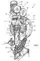
- a stranding machine according to the invention for stranding at least one wire W around a core C is generally indicated 1.
- the following description will refer, in non-limiting manner, to a single steel wire W to be arranged around a core C which, as will become clearer from the following description, is formed, at least in a starting phase, by suitable bending of a starting end portion of the wire W, so as to close it onto the wire itself.
- the core C is formed in a single piece with the wire W.
- the stranding machine 1 comprises a support frame 2 which extends from a base and supports the components of the machine.
- the stranding machine 1 comprises:
- the means 5 for holding the wire W comprise a wire-holder 13 which, in the embodiment shown, is in the form of a hollow cylindrical body extending along a predetermined axis Z-Z and having a lateral opening or window 28 from which the wire W emerges.
- the means 3 for guiding and supporting the core C are arranged so as to define a closed annular path around which the core is arranged, the core itself adopting a loop-like configuration.
- the guide and support means 3 are preferably arranged so as to define a circle.
- the means 3 for guiding and supporting the core comprise a plurality of rollers defining a roller bed 6 extending along a predetermined circular arc of the annular path and a wire-guide channel 7 positioned above the roller bed 6 in a diametrally opposed portion of the annular path. Both the wire-guide channel 7 and the roller bed 6 are positioned so as to be on the inside of the annular path.
- the diameter D of the annular path is defined by the distance between the roller bed 6 and the wire-guide channel 7.
- the annular path is thus a circle of diameter D contained in a vertical plane.
- the inside diameters of the stranded loops to be formed for example of 0.43 m, is thus substantially equal to the diameter D of the annular path.
- the roller bed 6 defines a cradle which extends around the lower inner portion of the annular path.
- the rollers may be covered with rubber or another equivalent material, and the portion of the wire-guide channel which is intended to come into contact with the steel wire is preferably covered with a material having a low coefficient of friction such as, for example, TeflonTM.
- the wire-guide channel 7 may be replaced by one or more rollers, or by a sliding surface.
- the pulling unit 4 comprises an endless chain 8 (i.e. a chain having the ends jointed together to form a loop) supported for rotation by a plurality of sprockets 10 supported by the frame 2.
- a plurality of sprockets 10 supported by the frame 2.
- one of the sprockets is kinematically connected to an electric motor 9 so as to be driven, enabling the chain 8 to be rotated.
- the chain 8 has a portion which is arranged around the annular path so as to be in contact with the core C so that the core is dragged along with the rotating chain and advanced around the annular path.
- the above-mentioned portion of the chain 8 is on the outside of the annular path and is positioned in the region of the roller bed 6. In the lower portion of the annular path, the core C therefore passes between the roller bed 6 and the chain 8 associated therewith.
- a chain-tensioner 14 is associated with the chain 8 and allows the chain to vary the space occupied by the loop of wire being formed, the cross-section of which increases as a result of the deposition of the wire W around the core C.
- the surfaces of the links of the chain 8 which are intended to come into contact with the core C are preferably covered with rubber or another equivalent material. This prevents direct contact between the wire and the links of the chain 8 and at the same time increases the coefficient of friction between the wire W and the links of the chain 8 so as to increase the dragging effect.
- the stranding machine 1 comprises kinematic means 12 for causing the means 5 for holding the wire Wand, in particular, the wire-holder 13, to move around the annular path with an interlinked rotary movement.
- the interlinked rotary movement of the wire-holder 13 consequently enables the wire W to be wound in a helix around the core C, that is, it enables the wire W to be stranded around the core C.
- the combination of the advancing movement of the core along the annular path and of the interlinked rotary movement of the wire-holder 13 thus enables a stranded loop of wire W to be formed.
- the kinematic means 12 preferably enable the wire-holder 13 to be moved around a point R on the annular path with a substantially planetary movement composed of:
- the two above-mentioned rotary movements of the wire-holder 13 are preferably synchronized with one another so as to avoid twisting of the wire about its own axis during the winding of the wire W in a helix around the core C.
- the wire-holder 13 is simultaneously rotated about itself in the opposite direction by one turn, consequently moving with plain motion.
- the second axis of rotation Y-Y extends through the wire-holder 13 so that the second rotary movement consists of a revolution of the wire-holder about itself.
- the above-mentioned planetary movement is therefore composed of a rotary movement of the entire wire-holder 13 about the interlinking axis X-X, and a simultaneous and opposite revolving movement of the wire-holder 13 about itself, about the axis Y-Y (the axis of revolution).
- the point R on the annular path about which the interlinked rotary movement of the wire-holder 13 takes place is positioned upstream of the combining point P, with reference to the direction of advance of the core C along the annular path.
- the wire W can thus be caused to reach the combining point P in a manner such as to be arranged around the core C, arriving substantially tangentially relative to the core along a stranding axis K-K.
- the stranding axis K-K and the interlinking axis X-X are therefore different.
- the interlinking axis X-X and the stranding axis K-K are coplanar and perpendicular to one another.
- the interlinking axis X-X extends through the point R so as to be tangential to the annular path ( Figure 3).
- the axis Y-Y about which the wire-holder 13 rotates about itself is preferably parallel to the interlinking axis X-X.
- the kinematic means 12 comprise:
- the ring gear 15 has an external set of teeth 27 and comprises a hub 20 which in turn bears an external set of teeth 24. So that the interlinking axis X-X is tangential to the annular path at the point R and, at the same time, also coincides with the axis of rotation of the ring gear 15, the hub 20 of the ring gear is hollow axially to allow the core C to extend through it.
- the circular continuity of the ring gear 15 is interrupted by a slot 21 which also extends radially through the hollow hub 20.
- the slot 21 enables the loop of stranded wire to be passed through the ring gear 15 when, upon completion of the stranding operation, it is necessary to remove the stranded loop 33 from the machine 1.
- the first gear train 16 comprises two pinions 22 which engage the outer set of teeth 27 of the ring gear 15 at two different points thereof.
- the two pinions 22 are connected to one another by an idler gear 23. This ensures both correct transmission of the drive from the drive means 18 to the ring gear 15 and a uniform transmission ratio between them, in spite of the discontinuity due to the presence of the slot 21.
- the second gear train 19 is in the form of an epicyclic gearing which takes the motion from the ring gear 15 and ensures de-twisting of the wire W.
- the second gear train 19 comprises two pinions 25 which mesh with different points on the external set of teeth 24 formed on the hub 20 of the ring gear 15.
- the two pinions 25 are connected to one another by an idler gear 26.
- the stranding machine 1 also comprises a unit for shaping the wire W, which is indicated 29 in the drawing and, with reference to the direction of advance of the core C around the annular path, is positioned immediately downstream of the point P at which the wire W is combined with the core C.
- the shaping unit 29 positions the wire W relative to the core C, possibly moving the turns of wire W already arranged around the core C in order to make room for the portion of wire which is being arranged.
- the shaping unit 29 also allows only the quantity of wire W necessary to cover the helix along which the wire W is arranged around the core C to be advanced towards the combining point P.
- the shaping unit is of the type with pulleys of which two are fixed pulleys 30 and one is a pulley 31 which swings away from and towards the wire W.
- the grooves of the pulleys enable the position adopted by the wire W during its deposition around the core C to be arranged in a manner such that the strand being formed has a substantially circular cross-section.
- the stranding machine 1 preferably also comprises a unit (not shown in the drawing) for splicing the end of the wire W between the other turns of the stranded loop 33.
- the wire-holder 13 is positioned with the axis Z-Z of the cylindrical body arranged transversely (perpendicularly in the embodiment shown in the drawing) relative to the axis X-X of the ring gear 15.
- the wire-holder 13 is associated with the ring gear 15 so as to be rotatable about itself about the axis of revolution Y-Y which is parallel to the interlinking axis X-X.
- the axis of revolution Y-Y is therefore perpendicular to the axis Z-Z of the cylindrical body of the wire-holder 13.
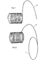
- the wire-holder 13 can house a length of wire W, for example, 7.5 m long, which is sufficient to form the stranded loop 33.
- the length of wire W to be inserted in the wire-holder is preferably shaped like a helical spring ( Figure 7).
- the lateral opening 28 of the wire-holder 13 faces towards the point P at which the wire W is combined with the core C.
- the opening 28 is formed in a cylindrical side wall of the cylindrical body and enables the wire W to emerge from the wire-holder 13 already facing the combining point P.
- the above-mentioned positioning of the wire-holder 13 and of its lateral opening 28 advantageously enables the wire W which has already emerged from the wire-holder 13 to be wound back into it. This prevents the portion of wire disposed between the wire-holder 13 and the combining point P from forming a bend during the interlinked rotary movement of the wire-holder 13 around the annular path. It should, in fact, be borne in mind that, during the rotary movement of the wire-holder 13, the distance between the lateral opening 28 and the combining point P is variable (see Figure 3) and, as stated above, the shaping unit 29 allows only the quantity of wire necessary to cover the helix in which the wire W is arranged around the core C to be advanced.
- a bend formed by the wire W would create problems caused by the wire interfering with the walls of the machine during the interlinked rotary movement and the formation of a bend would lead to a continual and undesired variation of the angle at which the wire W reaches the point P at which it is combined with the core C. Moreover, the formation of a bend in the wire would hinder the correct deposition of the wire W around the core C at the combining point P.
- the latter is movable angularly about the axis Z-Z of the cylindrical body through a predetermined, limited angle ⁇ , by way of example, of between 15° and 20°. This rotation of the wire-holder 13 prevents the wire from sticking relative to the wire-holder 13 instead of being rewound inside it.
- the wire-holder 13 is supported for rotation at its ends by two opposed prongs of a fork 32 the stem of which extends in the direction of the axis of revolution Y-Y.
- the stem of the fork 32 in turn is supported by the ring gear 15 so as to be rotatable about the axis of revolution Y-Y and is kinematically connected to the second gear train 19 in order to be rotated.
- Two stop elements associated with the prongs of the fork 32 ensure that the amplitude of the rotation of the wire-holder 13 about the axis Z-Z is limited to the desired angle ⁇ .
- the wire-holder 13 may be associated with the ring gear 15 so asto be idle relative to the ring gear 15, that is, to be free to rotate about the axis of revolution Y-Y, for example, owing to the interposition of a rolling bearing, and may have its centre of gravity offset, that is, eccentric, relative to the axis of revolution Y-Y.
- the centre of gravity of the wire-holder is eccentric relative to the axis of revolution, the wire-holder can thus always be kept oriented in the same manner by its own weight during the rotation of the ring gear 15 about the interlinking axis X-X.
- the stranding machine 1 also comprises conventional means for regulating the speed of the drive means 18 relative to the speed of advance of the core C around the annular path, imposed by the pulling unit 4. This enables the speed of the planetary movement of the wire-holder 13 to be synchronized relative to the speed of advance of the core C around the annular path in order to form around the core C a helical winding of the wire W having the desired pitch.
- the operation of the machine 1 is described below with reference to a starting condition in which the wire-holder 13 contains a length of wire W wound in a helix as indicated above and a starting end portion of the length of wire projects from the lateral window 28.
- the length of wire is 7.5 m long and is constituted by a steel wire having a diameter of 0.0035m.
- the starting end portion of the wire W is arranged around the annular path, starting from the shaping unit 29 (in an anticlockwise direction with reference to Figure 3).
- the starting end portion of the wire W thus passes between the roller bed 6 and the pulling unit 4 and through the wire-guide channel 7 until it reaches the point P at which it is fixed to the wire W.
- This starting end portion of the wire W thus forms the core C around which the remaining portion of the wire W is to be stranded ( Figure 8).
- the starting end of the wire W may be fixed to another point on the wire so as to form a closed loop constituting the core C by means of a known fastening technique.
- the fastening may be achieved with the use of a clamping element such as a clip or a lead seal, or by shaping a portion of the wire W in a loop, or even by shaping the starting end of the core C as a hook.
- the pulling unit 4 then causes the core C to advance around the annular path (in the anticlockwise direction indicated by the arrow F in Figure 3). Since the wire W is fastened to the core C, the advance of the core along the path causes the wire W to be drawn from the wire-holder 13.
- the wire-holder 13 at the same time moves with a planetary movement around the point R of the annular path.
- the planetary movement is composed of a rotation of the wire-holder 13 about the point R (in the clockwise direction indicated by the arrow H of Figure 4) and a simultaneous and opposed revolving rotary movement (in the anticlockwise direction indicated by the arrow T of Figure 4) of the wire-holder 13 about the axis Y-Y.
- the transmission ratio selected for the second gear train 19 is such that, for each complete rotation of the wire-holder 13 about the point R on the annular path, the wire-holder performs substantially one complete revolution about the axis Y-Y coinciding with the stem of the fork 32.
- the wire W drawn along by the core C is consequently arranged in a helix around the core C.
- the shaping unit 29 in wholly conventional manner arranges or positions the wire W during its deposition around the core C, possibly moving the turns of wire W already arranged around the core C to make room for the portion of wire which is being wound. The shaping unit 29 then sends back the excess wire W, allowing only the quantity of wire W necessary to cover the helix along which the wire is arranged around the core to advance towards the combining point P.
- the stranding machine 1 When all of the wire W has been arranged (wound) around the core C, the stranding machine 1 is stopped and, after the tail end of the wire W has been secured, the stranded loop 33 can be removed from the guiding and support means 3 by virtue of the slot 21 in the ring gear 15 and in the hub 20.
- the tail end of the wire W can be secured with the use of the splicing unit with which the stranding machine 1 is provided. Alternatively, the splicing may be performed outside the machine 1.
- a stranded loop 33 is to be formed in a manner such that it is linked with one or more stranded loops 34 already formed so as to form a net, it suffices to position the already-formed loops 34 straddling the cradle defined by the roller bed 6 before arranging the core C around the annular path. When the core C is then arranged around the annular path, it interlinks the loops 34 already formed.
- the stranding machine 1 can produce a closed loop formed by two or more wires stranded together or in successive steps. Similarly, instead of using a wire W, it is possible to use a strand or several strands simultaneously.
- the stranding machine 1 may be mounted on wheels or on a track perpendicular to the interlinking axis X-X so as to be movable sideways. This enables the stranding machine to be moved along the protective net 35 which is being constructed, whilst the net 35 is kept hanging in a fixed position.
- the method of forming a loop of stranded wire according to the invention comprises the steps of:
- the tail end of the wire is preferably secured by being spliced between the turns of wire of the stranded loop 33.
- the splicing may advantageously be performed by replacing a portion of the starting end of the wire with a tail end portion thereof. This is done by removing a portion of wire from the turns of the stranded loop 33, starting from the starting end of the wire W, that is, a starting portion of the core C, and inserting the tail end of the wire in its place by splicing.
- the core C of the stranded loop 33 is thus formed by a portion of the starting end and by a portion of the tail end of the wire, respectively.
- the stranding operation is preferably performed starting with a length of wire to be stranded, arranged in the form of a helical spring ( Figure 7).
- the core is advantageously formed in a single piece with the wire, the core being formed by an end portion of the wire which is arranged around the annular path so as to form a loop closed onto itself by fastening.
- the core may be formed by a wire separate from the wire to be stranded.
- the wire to be stranded around the core arrives at the combining point so as to be substantially tangential to the core and, during the stranding, is rotated about itself with an opposite direction of rotation to that of the interlinked rotary movement about the point on the annular path.
- This prevents twists arising in the wire due to the interlinked rotary movement.
- This is particularly advantageous when the wire to be stranded is made of steel.
- the stranded loop 33 may be formed by the stranding of two or more wires or of one or more strands, simultaneously, or in successive steps.
- the stranded loops may also be formed with a wire or thread of a material other than steel such as, for example NylonTM.
- the protective net formed by the method according to the invention may also be used for uses other than those indicated in the initial part of the description.
- the net may be used to protect marine fish farms from intrusion by seals or killer whales.
- the diameter of the stranded loops should be selected on the basis of the specific requirements to be satisfied.
- the stranding machine according to the invention has structural and functional characteristics such as to satisfy the above-mentioned requirements and at the same time to solve the problems referred to.
- the loop formed is constituted by several turns of wire which are stranded together and which do not require elements such as clamping clips and the like to keep them close together.
- the stranded loop can be closed onto itself by splicing the tail end of the wire between the other turns of the loop.
- the wire constituting the turns is pulled onto itself, closing up the turns to a greater extent and preventing the wire from slipping.
- the wire therefore advantageously works in torsion and not simply in tension as in the non-stranded loops of the prior art.
- the planetary movement of the wire-holding means relative to the annular path and to the core prevents the wire arranged in a helix from generating twisting tensions during the stranding.
- Another advantage of the stranding machine according to the invention lies in the fact that it can produce a stranded loop linked with other loops.
- a further advantage of the stranding machine according to the invention lies in the fact that it can be automated.
- the method according to the invention enables stranded loops with good strength characteristics to be produced easily and in an economically advantageous manner.
- the stranding machine may be supported from above, so as to be suspended, instead of being supported by a base. This leaves the space beneath the machine free, preventing the meshes of the protective net being formed from interfering with the base. This same advantage may be achieved with a C-shaped base.
- the ring gear 15 may be formed in a manner such as to be divisible into two or more parts joined together releasably. In this case, in order to remove the loop of stranded wire from the machine, it is necessary to split the ring gear.
- the shaping unit may, for example, be formed by a die which can be divided into two halves.
- a wire-holder comprising an open reel instead of a closed cylindrical body may be used.
- the wire-holder may be replaced by a bobbin or by a reel.
- the above-mentioned recovery of the wire by the wire-holding means may be performed by spring or friction devices or by other functionally equivalent devices.
- the two gear trains may be replaced, at least partially, by functionally equivalent mechanical transmission means such as, for example, toothed belt or chain transmissions.
Claims (41)
- Machine à toronner (1) permettant de toronner au moins un fil (M) autour d'une âme (C), comprenant :ladite machine à toronner étant caractérisée en ce que la machine à toronner (1) comprend un arceau (6) le long du chemin annulaire, approprié pour placer la boucle toronnée (33) dans une position écartée, une autre âme agencée le long du chemin annulaire étant reliée à ladite boucle toronnée (33).des moyens (3) permettant de guider et de supporter une âme (C), agencés autour d'un chemin annulaire pour amener l'âme (C) à adopter une configuration en forme de boucle,des moyens (5) permettant de retenir au moins un fil (W) devant être agencé autour de l'âme (C) et relié à l'âme, les moyens de retenue (5) permettant au fil (W) d'avancer vers un point (P) au niveau duquel il est combiné à l'âme (C),des moyens cinématiques (12) destinés à déplacer les moyens (5) permettant de retenir le fil (W) autour du chemin annulaire avec un mouvement conjugué, etune unité de traction (4) permettant de faire avancer l'âme (C) autour du chemin annulaire et de faire glisser le fil (W) vers le point (P) au niveau duquel il est combiné à l'âme (C) de manière à produire une boucle toronnée (33) formée par le au moins un fil (W) agencé en hélice autour de l'âme (C),
- Machine à toronner (1) selon la revendication 1, dans laquelle ledit arceau est défini par un lit de rouleaux (6).
- Machine à toronner selon la revendication 2, dans laquelle ledit lit de rouleaux comprend une pluralité de rouleaux des moyens (3) permettant de guider et de supporter l'âme (C).
- Machine à toronner (1) selon la revendication 1, dans laquelle lesdits moyens cinématiques (12) comprennent une couronne dentée rotative (15) positionnée de manière à être en liaison avec le chemin annulaire.
- Machine à toronner (1) selon la revendication 4, dans laquelle la couronne dentée (15) des moyens cinématiques est interrompue par une fente (21).
- Machine à toronner (1) selon la revendication 5, dans laquelle ladite fente (21) s'étend radialement au travers de la couronne (15) depuis la périphérie jusqu'au centre de ladite couronne.
- Machine à toronner (1) selon la revendication 1, dans laquelle les moyens (5) permettant de retenir le fil (W) se déplacent autour d'un point (R) sur le chemin annulaire ayant un mouvement sensiblement planétaire, comprenant :un premier mouvement rotatif autour d'un axe d'interconnexion (X-X), le premier mouvement rotatif étant en liaison avec le chemin annulaire,un deuxième mouvement rotatif des moyens (5) permettant de retenir le fil (W) autour de lui-même, autour d'un deuxième axe de rotation (Y-Y), le deuxième mouvement rotatif ayant un sens opposé au sens de rotation du premier mouvement rotatif.
- Machine à toronner (1) selon la revendication 7, dans lequel les premier et deuxième mouvements rotatifs des moyens (5) permettant de retenir le fil (W) sont synchronisés de manière à empêcher la torsion du fil (W) autour de son propre axe.
- Machine à toronner (1) selon la revendication 7, comprenant des moyens permettant de réguler la vitesse du mouvement conjugué des moyens (5) permettant de retenir le fil (W) par rapport à la vitesse d'avancement de l'unité de traction (4) afin de former autour de l'âme (C) un enroulement hélicoïdal du fil (W) ayant un pas uniforme prédéterminé.
- Machine à toronner (1) selon l'une quelconque des revendications 4 et 7, dans laquelle la couronne dentée (15) est reliée, d'un point de vue cinématique, à un châssis de support (2) de manière à pouvoir pivoter autour de l'axe d'interconnexion (X-X), les moyens (5) permettant de retenir le fil (W) étant associés à la couronne dentée (15) de manière à pouvoir tourner autour du deuxième axe de rotation (Y-Y).
- Machine à toronner (1) selon l'une quelconque des revendications 4 et 7, dans laquelle un premier train d'engrenages (16) relie d'un point de vue cinématique la couronne dentée (15) à des premiers moyens d'entraínement (18) afin de générer le premier mouvement rotatif des moyens (5) permettant de retenir le fil (W).
- Machine à toronner (1) selon la revendication 11, dans laquelle les moyens cinématiques (12) comprennent un deuxième train d'engrenages (19), qui relie d'un point de vue cinématique la couronne dentée (15) aux moyens (5) permettant de retenir le fil (W) afin de générer le deuxième mouvement rotatif des moyens (5) permettant de retenir le fil (W) et d'empêcher la torsion du fil (W).
- Machine à toronner (1) selon la revendication 4, dans laquelle les moyens (5) permettant de retenir le fil (W) sont supportés par la couronne dentée (15) de manière à pouvoir tourner librement, les moyens permettant de retenir le fil ayant un centre de gravité qui est excentrique par rapport au deuxième axe de rotation.
- Machine à toronner (1) selon la revendication 13, dans lequel les moyens sont associés aux moyens permettant de retenir le fil, pour éliminer les mouvements d'oscillation des moyens permettant de retenir le fil en raison des forces d'inertie pendant la rotation de la couronne dentée (15).
- Machine à toronner (1) selon la revendication 7, dans laquelle l'axe d'interconnexion (X-X) et le deuxième axe de rotation (Y-Y) sont parallèles l'un à l'autre.
- Machine à toronner (1) selon la revendication 9, dans laquelle le point (R) sur le chemin annulaire est positionné en amont du point de combinaison (P), en faisant référence au sens d'avancement de l'âme (C) le long du chemin annulaire.
- Machine à toronner (1) selon l'une quelconque des revendications 4 et 7, dans laquelle l'axe d'interconnexion (X-X) coïncide avec l'axe de la couronne dentée (15) et est tangent au point (R) sur le chemin annulaire.
- Machine à toronner (1) selon la revendication 4, dans laquelle la couronne dentée (15) comprend un jeu externe de dents (27).
- Machine à toronner (1) selon l'une quelconque des revendications 11 et 18, dans laquelle le premier train d'engrenages (16) comprenant au moins deux pignons (22) s'engrène avec le jeu externe de dents (27) de la couronne dentée (15) au niveau de différents points de celle-ci.
- Machine à toronner (1) selon la revendication 19, dans laquelle les au moins deux pignons (22) sont reliés par un engrenage intermédiaire (23).
- Machine à toronner (1) selon la revendication 5, dans laquelle la couronne dentée (15) comprend un moyeu creux (20) au travers duquel peut s'étendre l'âme (C), et dans laquelle la fente (21) s'étend également vers le moyeu creux (20).
- Machine à toronner (1) selon la revendication 12, dans laquelle le deuxième train d'engrenages (19) comprend au moins deux pignons (25) qui s'engrènent avec un jeu de dents (24) de la couronne dentée (15) au niveau de différents points de celle-ci.
- Machine à toronner (1) selon l'une quelconque des revendications 21 et 22, dans laquelle les pignons (25) s'engrènent avec un jeu externe de dents (24) formées sur le moyeu creux (20) de la couronne dentée (15).
- Machine à toronner (1) selon la revendication 1, dans laquelle les moyens (5) permettant de retenir le fil (W) comprennent un porte-fil (13) qui peut recouvrir la partie de fil (W) déroulée du porte-fil pendant le mouvement conjugué de celui-ci.
- Machine à toronner selon la revendication 24, dans laquelle le porte-fil (13) comprend un corps cylindrique s'étendant le long d'un axe prédéterminé (Z-Z) et ayant une ouverture latérale (28) permettant au fil (W) de sortir.
- Machine à toronner (1) selon la revendication 25, dans laquelle l'ouverture dans le corps cylindrique est orientée vers le point (P) au niveau duquel le fil (W) est combiné à l'âme (C).
- Machine à toronner (1) selon l'une quelconque des revendications 25 ou 26, dans laquelle l'axe (Z-Z) du porte-fil (13) est transversal par rapport à l'axe de la couronne dentée (15).
- Machine à toronner (1) selon la revendication 24, dans laquelle le porte-fil (13) peut se déplacer de manière angulaire sur un angle prédéterminé (α) autour de son propre axe (Z-Z).
- Machine à toronner (1) selon la revendication 1, dans laquelle l'unité de traction (4) comprend une unité de glissement avec une chaíne entraínée (8) agissant sur l'âme en forme de boucle (C).
- Machine à toronner (1) selon la revendication 1, comprenant une unité (29) permettant de former le fil (W), l'unité (29) étant positionnée en aval du point de combinaison (P) en faisant référence au sens d'avancement de l'âme (C) le long du chemin annulaire.
- Machine à toronner (1) selon la revendication 1, comprenant une unité permettant d'épisser une extrémité de queue du fil (W) entre les spires de la boucle toronnée (33).
- Procédé de formation d'un filet (35) comprenant les étapes consistant à :former une boucle de fil toronné autour d'une âme (C) guidée et supportée par les moyens (3) permettant de guider et de supporter ladite âme d'une machine à toronner (1) ;retirer ladite boucle toronnée (34) desdits moyens (3) permettant de guider et de supporter ladite âme ;positionner la boucle toronnée (34) en position écartée sur un arceau ;former une autre boucle toronnée (33) après avoir relié entre elles l'âme (C) de l'autre boucle toronnée (33) devant être formée et l'une des plusieurs boucles toronnées (34) préparées en amenant l'âme (C) à s'étendre au travers des boucles.
- Procédé de formation d'un filet (35) selon la revendication 32, dans lequel l'étape de formation d'une boucle de fil toronné comprend les étapes consistant à :agencer une âme (C) de fil (W) autour d'un chemin annulaire ;prévoir au moins une longueur de fil (W) qui doit être toronnée avec l'âme (C) et qui présente une extrémité de début et une extrémité de queue,serrer le au moins un fil (W) sur l'âme (C) au niveau d'un point de combinaison (P),faire avancer l'âme (C) autour du chemin annulaire, déplacer le au moins un fil (W) autour d'un point sur le chemin annulaire avec un mouvement rotatif conjugué de manière à enrouler le fil (C) en hélice autour de l'âme (C).
- Procédé de formation d'un filet (35) selon la revendication 33, dans lequel l'étape de formation d'une boucle de fil toronné comprend l'étape consistant à fixer l'extrémité de queue du fil (W).
- Procédé de formation d'un filet (35) selon la revendication 34, dans lequel l'étape consistant à fixer l'extrémité de queue du fil (W) comprend l'épissure de l'extrémité de queue du fil (W) entre les spires du fil toronné (W) de la boucle.
- Procédé de formation d'un filet (35) selon la revendication 35, dans lequel l'étape consistant à fixer l'extrémité de queue du fil (W) comprend l'étape consistant à retirer une partie de fil (W) des spires de fil toronné (W), en commençant par l'extrémité du début du fil (W) et en insérant l'extrémité de queue du fil (W) à sa place à l'aide d'une épissure.
- Procédé de formation d'un filet (35) selon la revendication 32, dans lequel la longueur de fil (W) devant être toronnée est agencée sous la forme d'un ressort hélicoïdal.
- Procédé de formation d'un filet (35) selon la revendication 32, dans lequel l'âme (C) est formée en seule pièce avec le fil (W), l'âme (C) étant formée par une partie de l'extrémité du début du fil (W) agencée autour du chemin pour former une boucle refermée sur elle-même à l'aide d'un serrage.
- Procédé de formation d'un filet (35) selon la revendication 33, dans lequel le fil (W) arrive au niveau d'un point de combinaison (P) de manière à être sensiblement tangentiel par rapport à l'âme (C).
- Procédé de formation d'un filet (35) selon la revendication 33, dans lequel le fil (W) est tourné sur lui-même avec un sens opposé de rotation par rapport à celui du mouvement rotatif conjugué du fil (W) autour d'un point sur le chemin annulaire, en empêchant la torsion du fil (W) due au mouvement rotatif conjugué.
- Procédé de formation d'un filet (35) selon la revendication 33, dans lequel le fil (W) est réalisé en acier.
Applications Claiming Priority (1)
| Application Number | Priority Date | Filing Date | Title |
|---|---|---|---|
| PCT/IT2000/000047 WO2001060547A1 (fr) | 2000-02-15 | 2000-02-15 | Machine et procede permettant d'enrouler un fil de maniere helicoidale autour d'un coeur annulaire |
Publications (2)
| Publication Number | Publication Date |
|---|---|
| EP1255623A1 EP1255623A1 (fr) | 2002-11-13 |
| EP1255623B1 true EP1255623B1 (fr) | 2004-01-21 |
Family
ID=11133486
Family Applications (1)
| Application Number | Title | Priority Date | Filing Date |
|---|---|---|---|
| EP00909617A Expired - Lifetime EP1255623B1 (fr) | 2000-02-15 | 2000-02-15 | Machine et procede permettant d'enrouler un fil de maniere helicoidale autour d'un coeur annulaire |
Country Status (6)
| Country | Link |
|---|---|
| EP (1) | EP1255623B1 (fr) |
| AT (1) | ATE258087T1 (fr) |
| AU (1) | AU2000231896A1 (fr) |
| DE (1) | DE60007902D1 (fr) |
| SK (1) | SK10642002A3 (fr) |
| WO (1) | WO2001060547A1 (fr) |
Families Citing this family (5)
| Publication number | Priority date | Publication date | Assignee | Title |
|---|---|---|---|---|
| FR2838462B1 (fr) * | 2002-04-12 | 2004-10-08 | Patrick Rentchler | Barriere de protection dynamique contre les chutes de rochers dont le filet est forme de mailles entrelacees |
| ITMI20031601A1 (it) * | 2003-08-04 | 2005-02-05 | Italgeo S R L | Rete ad anelli di filo, particolarmente per barriere paramassi e rivestimenti di parete rocciose, nonche' procedimento per la realizzazione della rete. |
| CH697125A5 (de) * | 2004-11-26 | 2008-05-15 | Fatzer Ag | Ringförmiges Element sowie ein Auffangnetz bestehend aus derartigen Elementen. |
| JP5043401B2 (ja) * | 2005-11-10 | 2012-10-10 | 住友電工スチールワイヤー株式会社 | 環状金属コード及び無端金属ベルト |
| EP3573455B1 (fr) * | 2017-01-27 | 2020-10-14 | Officine Maccaferri S.p.A. | Filet de protection comprenant des boucles hautement résilientes |
Family Cites Families (3)
| Publication number | Priority date | Publication date | Assignee | Title |
|---|---|---|---|---|
| US1570821A (en) * | 1921-09-23 | 1926-01-26 | John R Gammeter | Machine for the manufacture of bead cables or grommets |
| JPS5327382B2 (fr) * | 1973-06-23 | 1978-08-08 | ||
| CA2145829C (fr) * | 1994-04-08 | 2003-03-18 | Bernhard Eicher | Methode et appareil pour la production d'un filet de retenue |
-
2000
- 2000-02-15 AU AU2000231896A patent/AU2000231896A1/en not_active Abandoned
- 2000-02-15 AT AT00909617T patent/ATE258087T1/de not_active IP Right Cessation
- 2000-02-15 WO PCT/IT2000/000047 patent/WO2001060547A1/fr active IP Right Grant
- 2000-02-15 EP EP00909617A patent/EP1255623B1/fr not_active Expired - Lifetime
- 2000-02-15 DE DE60007902T patent/DE60007902D1/de not_active Expired - Lifetime
- 2000-02-15 SK SK1064-2002A patent/SK10642002A3/sk unknown
Also Published As
| Publication number | Publication date |
|---|---|
| SK10642002A3 (sk) | 2002-11-06 |
| DE60007902D1 (de) | 2004-02-26 |
| EP1255623A1 (fr) | 2002-11-13 |
| AU2000231896A1 (en) | 2001-08-27 |
| WO2001060547A1 (fr) | 2001-08-23 |
| ATE258087T1 (de) | 2004-02-15 |
Similar Documents
| Publication | Publication Date | Title |
|---|---|---|
| US4779411A (en) | Flexible, non-metallic rigging chain | |
| TWI704089B (zh) | 鐵筋捆束機 | |
| EP2913434B1 (fr) | Procédé de formation d'un oeil dans une partie d'une corde | |
| EP1255623B1 (fr) | Machine et procede permettant d'enrouler un fil de maniere helicoidale autour d'un coeur annulaire | |
| DK179010B1 (en) | Manufacture method and apparatus for improved efficiency reduced cost rope for pelagic trawls | |
| CN101981772A (zh) | 用于将缆索的索股牵引到管道内的方法和相应系统 | |
| US4341065A (en) | Production of bindings of fiber bundles | |
| JPS6121917B2 (fr) | ||
| KR101123930B1 (ko) | 와이어 코드 제조 방법 및 제조 장치 | |
| US3426519A (en) | Apparatus for stranding fibers with reversing twist | |
| NZ205050A (en) | Introducing filler material into helix used to produce helix belt composed of multiplicity of such helices meshing with one another and connected by pintle wire | |
| JP2879667B2 (ja) | ケーブル先導案内装置 | |
| JPS6233359B2 (fr) | ||
| CN210558872U (zh) | 长距离两头扣环形吊带生产线 | |
| JP2879669B2 (ja) | ケーブル先導案内装置 | |
| CN211239116U (zh) | 一种叉车线束编织带的穿管装置 | |
| CA1069284A (fr) | Methode et appareil pour la construction d'un ouvrage a surfaces planes | |
| US630334A (en) | Machine for making lightning-rods. | |
| US4910952A (en) | Method and apparatus for making a frayless line | |
| KR102013591B1 (ko) | 심선 교체에 의한 광섬유 센서 내장 심선을 구비한 스마트 강연선 제작장치 및 제작방법 | |
| CN113401725B (zh) | 一种高分子编织绳成型装置 | |
| RU2067510C1 (ru) | Способ изготовления крученой проволочной сетки и устройство для его осуществления | |
| CN117926486A (zh) | 一种复合纤维织带制备工艺及其制备装置 | |
| RU122387U1 (ru) | Станок для изготовления круглопрядных строп | |
| JP2879668B2 (ja) | ケーブル先導案内装置 |
Legal Events
| Date | Code | Title | Description |
|---|---|---|---|
| PUAI | Public reference made under article 153(3) epc to a published international application that has entered the european phase |
Free format text: ORIGINAL CODE: 0009012 |
|
| 17P | Request for examination filed |
Effective date: 20020717 |
|
| AK | Designated contracting states |
Kind code of ref document: A1 Designated state(s): AT BE CH CY DE DK ES FI FR GB GR IE IT LI LU MC NL PT SE |
|
| AX | Request for extension of the european patent |
Free format text: AL PAYMENT 20020717;LT PAYMENT 20020717;LV PAYMENT 20020717;MK PAYMENT 20020717;RO PAYMENT 20020717;SI PAYMENT 20020717 |
|
| GRAP | Despatch of communication of intention to grant a patent |
Free format text: ORIGINAL CODE: EPIDOSNIGR1 |
|
| GRAS | Grant fee paid |
Free format text: ORIGINAL CODE: EPIDOSNIGR3 |
|
| GRAA | (expected) grant |
Free format text: ORIGINAL CODE: 0009210 |
|
| AK | Designated contracting states |
Kind code of ref document: B1 Designated state(s): AT BE CH CY DE DK ES FI FR GB GR IE IT LI LU MC NL PT SE |
|
| AX | Request for extension of the european patent |
Extension state: AL LT LV MK RO SI |
|
| PG25 | Lapsed in a contracting state [announced via postgrant information from national office to epo] |
Ref country code: AT Free format text: LAPSE BECAUSE OF FAILURE TO SUBMIT A TRANSLATION OF THE DESCRIPTION OR TO PAY THE FEE WITHIN THE PRESCRIBED TIME-LIMIT Effective date: 20040121 Ref country code: BE Free format text: LAPSE BECAUSE OF FAILURE TO SUBMIT A TRANSLATION OF THE DESCRIPTION OR TO PAY THE FEE WITHIN THE PRESCRIBED TIME-LIMIT Effective date: 20040121 Ref country code: NL Free format text: LAPSE BECAUSE OF FAILURE TO SUBMIT A TRANSLATION OF THE DESCRIPTION OR TO PAY THE FEE WITHIN THE PRESCRIBED TIME-LIMIT Effective date: 20040121 Ref country code: FI Free format text: LAPSE BECAUSE OF FAILURE TO SUBMIT A TRANSLATION OF THE DESCRIPTION OR TO PAY THE FEE WITHIN THE PRESCRIBED TIME-LIMIT Effective date: 20040121 Ref country code: CY Free format text: LAPSE BECAUSE OF FAILURE TO SUBMIT A TRANSLATION OF THE DESCRIPTION OR TO PAY THE FEE WITHIN THE PRESCRIBED TIME-LIMIT Effective date: 20040121 |
|
| REG | Reference to a national code |
Ref country code: GB Ref legal event code: FG4D |
|
| REG | Reference to a national code |
Ref country code: CH Ref legal event code: EP |
|
| PG25 | Lapsed in a contracting state [announced via postgrant information from national office to epo] |
Ref country code: LU Free format text: LAPSE BECAUSE OF NON-PAYMENT OF DUE FEES Effective date: 20040215 |
|
| PG25 | Lapsed in a contracting state [announced via postgrant information from national office to epo] |
Ref country code: IE Free format text: LAPSE BECAUSE OF NON-PAYMENT OF DUE FEES Effective date: 20040216 |
|
| REG | Reference to a national code |
Ref country code: IE Ref legal event code: FG4D |
|
| REF | Corresponds to: |
Ref document number: 60007902 Country of ref document: DE Date of ref document: 20040226 Kind code of ref document: P |
|
| PG25 | Lapsed in a contracting state [announced via postgrant information from national office to epo] |
Ref country code: MC Free format text: LAPSE BECAUSE OF NON-PAYMENT OF DUE FEES Effective date: 20040228 |
|
| PG25 | Lapsed in a contracting state [announced via postgrant information from national office to epo] |
Ref country code: GB Free format text: LAPSE BECAUSE OF NON-PAYMENT OF DUE FEES Effective date: 20040421 Ref country code: DK Free format text: LAPSE BECAUSE OF FAILURE TO SUBMIT A TRANSLATION OF THE DESCRIPTION OR TO PAY THE FEE WITHIN THE PRESCRIBED TIME-LIMIT Effective date: 20040421 Ref country code: SE Free format text: LAPSE BECAUSE OF FAILURE TO SUBMIT A TRANSLATION OF THE DESCRIPTION OR TO PAY THE FEE WITHIN THE PRESCRIBED TIME-LIMIT Effective date: 20040421 Ref country code: GR Free format text: LAPSE BECAUSE OF FAILURE TO SUBMIT A TRANSLATION OF THE DESCRIPTION OR TO PAY THE FEE WITHIN THE PRESCRIBED TIME-LIMIT Effective date: 20040421 |
|
| PG25 | Lapsed in a contracting state [announced via postgrant information from national office to epo] |
Ref country code: DE Free format text: LAPSE BECAUSE OF FAILURE TO SUBMIT A TRANSLATION OF THE DESCRIPTION OR TO PAY THE FEE WITHIN THE PRESCRIBED TIME-LIMIT Effective date: 20040422 |
|
| REG | Reference to a national code |
Ref country code: CH Ref legal event code: NV Representative=s name: JACOBACCI & PARTNERS S.P.A. |
|
| PG25 | Lapsed in a contracting state [announced via postgrant information from national office to epo] |
Ref country code: ES Free format text: LAPSE BECAUSE OF FAILURE TO SUBMIT A TRANSLATION OF THE DESCRIPTION OR TO PAY THE FEE WITHIN THE PRESCRIBED TIME-LIMIT Effective date: 20040502 |
|
| LTIE | Lt: invalidation of european patent or patent extension |
Effective date: 20040121 |
|
| NLV1 | Nl: lapsed or annulled due to failure to fulfill the requirements of art. 29p and 29m of the patents act | ||
| ET | Fr: translation filed | ||
| REG | Reference to a national code |
Ref country code: IE Ref legal event code: MM4A |
|
| PLBE | No opposition filed within time limit |
Free format text: ORIGINAL CODE: 0009261 |
|
| STAA | Information on the status of an ep patent application or granted ep patent |
Free format text: STATUS: NO OPPOSITION FILED WITHIN TIME LIMIT |
|
| GBPC | Gb: european patent ceased through non-payment of renewal fee |
Effective date: 20040421 |
|
| 26N | No opposition filed |
Effective date: 20041022 |
|
| PGFP | Annual fee paid to national office [announced via postgrant information from national office to epo] |
Ref country code: CH Payment date: 20060118 Year of fee payment: 7 |
|
| PGFP | Annual fee paid to national office [announced via postgrant information from national office to epo] |
Ref country code: FR Payment date: 20060228 Year of fee payment: 7 |
|
| PG25 | Lapsed in a contracting state [announced via postgrant information from national office to epo] |
Ref country code: LI Free format text: LAPSE BECAUSE OF NON-PAYMENT OF DUE FEES Effective date: 20070228 Ref country code: CH Free format text: LAPSE BECAUSE OF NON-PAYMENT OF DUE FEES Effective date: 20070228 |
|
| REG | Reference to a national code |
Ref country code: CH Ref legal event code: PL |
|
| REG | Reference to a national code |
Ref country code: FR Ref legal event code: ST Effective date: 20071030 |
|
| PG25 | Lapsed in a contracting state [announced via postgrant information from national office to epo] |
Ref country code: PT Free format text: LAPSE BECAUSE OF NON-PAYMENT OF DUE FEES Effective date: 20040621 |
|
| PG25 | Lapsed in a contracting state [announced via postgrant information from national office to epo] |
Ref country code: FR Free format text: LAPSE BECAUSE OF NON-PAYMENT OF DUE FEES Effective date: 20070228 |
|
| PGFP | Annual fee paid to national office [announced via postgrant information from national office to epo] |
Ref country code: IT Payment date: 20120224 Year of fee payment: 13 |
|
| PG25 | Lapsed in a contracting state [announced via postgrant information from national office to epo] |
Ref country code: IT Free format text: LAPSE BECAUSE OF NON-PAYMENT OF DUE FEES Effective date: 20140215 |