EP1255152A2 - Box transformable in a stereoscopic viewing system - Google Patents
Box transformable in a stereoscopic viewing system Download PDFInfo
- Publication number
- EP1255152A2 EP1255152A2 EP02290548A EP02290548A EP1255152A2 EP 1255152 A2 EP1255152 A2 EP 1255152A2 EP 02290548 A EP02290548 A EP 02290548A EP 02290548 A EP02290548 A EP 02290548A EP 1255152 A2 EP1255152 A2 EP 1255152A2
- Authority
- EP
- European Patent Office
- Prior art keywords
- front wall
- wall
- box
- detachment
- detachable element
- Prior art date
- Legal status (The legal status is an assumption and is not a legal conclusion. Google has not performed a legal analysis and makes no representation as to the accuracy of the status listed.)
- Withdrawn
Links
Images


Classifications
-
- G—PHYSICS
- G02—OPTICS
- G02B—OPTICAL ELEMENTS, SYSTEMS OR APPARATUS
- G02B30/00—Optical systems or apparatus for producing three-dimensional [3D] effects, e.g. stereoscopic images
- G02B30/20—Optical systems or apparatus for producing three-dimensional [3D] effects, e.g. stereoscopic images by providing first and second parallax images to an observer's left and right eyes
- G02B30/34—Stereoscopes providing a stereoscopic pair of separated images corresponding to parallactically displaced views of the same object, e.g. three-dimensional [3D] slide viewers
- G02B30/37—Collapsible stereoscopes
Definitions
- the invention relates to a box convertible into a viewer stereoscopic.
- the invention relates in particular to but not exclusively cardboard boxes used for food packaging.
- stereoscopic viewers formed by a precut blank defining a foldable structure, this structure including a support wall for a double image and a binocular vision wall opposite the support wall, the two walls being connected by foldable links of so the viewer can be stored flat.
- a blank is for a very specific use, and can in no case be used for another application.
- a transformable box having a front wall and walls adjacent to the wall frontal, at least some of these walls comprising pre-cuts delimiting partially wall elements or fully detachable.
- the wall front has at least one detachable element allowing, after detachment, binocular vision at the inside of the box, and at least one of the adjacent walls at the front wall has at least one detachable element allowing, after detachment, access for the surrounding light inside the box, a way to support being further arranged inside the box distance from the front wall to support a double image opposite the front wall at a distance therefrom.
- the box when the detachable items are not detached, the box performs its primary function as a container, and when the detachable elements are detached, the box is transformed into a viewer which, by reporting a binocular magnifier on the first wall, allows vision stereoscopic of a double image arranged on or against the support means.
- the detachable element of the first wall has two portions spaced apart from one eye. We can thus adequately adapt a magnifying glass binocular with two circular lenses.
- the front wall has two pre-cuts made on either side of the element detachable from the front wall, these pre-cuts forming, after detachment, slots for the installation of a binocular optics.
- an adjacent wall at the front wall has a detachable element having a fold line extending along a wall back of the box opposite the front wall, the wall rear constituting, after detachment, the means of dual image support.
- the detachable element allows everything at the same time access to the rear wall used to support the image double and access to the surrounding light towards said wall back.
- the detachable element can then be left in a position parallel to the back side to help dual image support.
- the wall adjacent to the wall front also includes two pre-cuts extending on either side of the detachable element along the rear wall in the vicinity thereof, these precuts constituting after detachment a suitable slide system to receive the double image.
- This slide system facilitates installation of the double image and stabilizes it against the rear wall.
- a wall adjacent to the front wall comprises a detachable element delimited by a precut a rear portion of which extends along a rear wall of the box opposite the front wall, the wall rear component, after detachment of the precut, the dual image support means.
- the detachable element is composed two flaps extending to the rear wall and each having a fold line extending perpendicularly at the rear wall, the flaps in the folded position in the box and the back defining after detachment a slide system capable of receiving the double image.
- notches extend parallel to the front wall straddling the fold lines of each of the flaps to constitute, after detachment, the means for supporting the double image when the flaps are folded down.
- a wall adjacent to the front wall has a first element detachable delimited by a precut including a rear portion extends parallel to the front wall to define a support edge after detachment of the first element detachable, the same adjacent wall further comprising a second detachable element extending to the support edge and having a fold line perpendicular to this edge support, the support edge and the second element in position folded around the fold line constituting, after detachment, the means of supporting the double image.
- the support means can again be positioned at an arbitrary distance from the front wall, lower at the distance between the front wall and the wall back of the box.
- the first detachable element is made up of two parts extending up to support and each having a fold line extending perpendicularly at the free edge, the flaps in the folded position in the box and the free edge defining, after detachment, a slide system capable of receiving the double image.
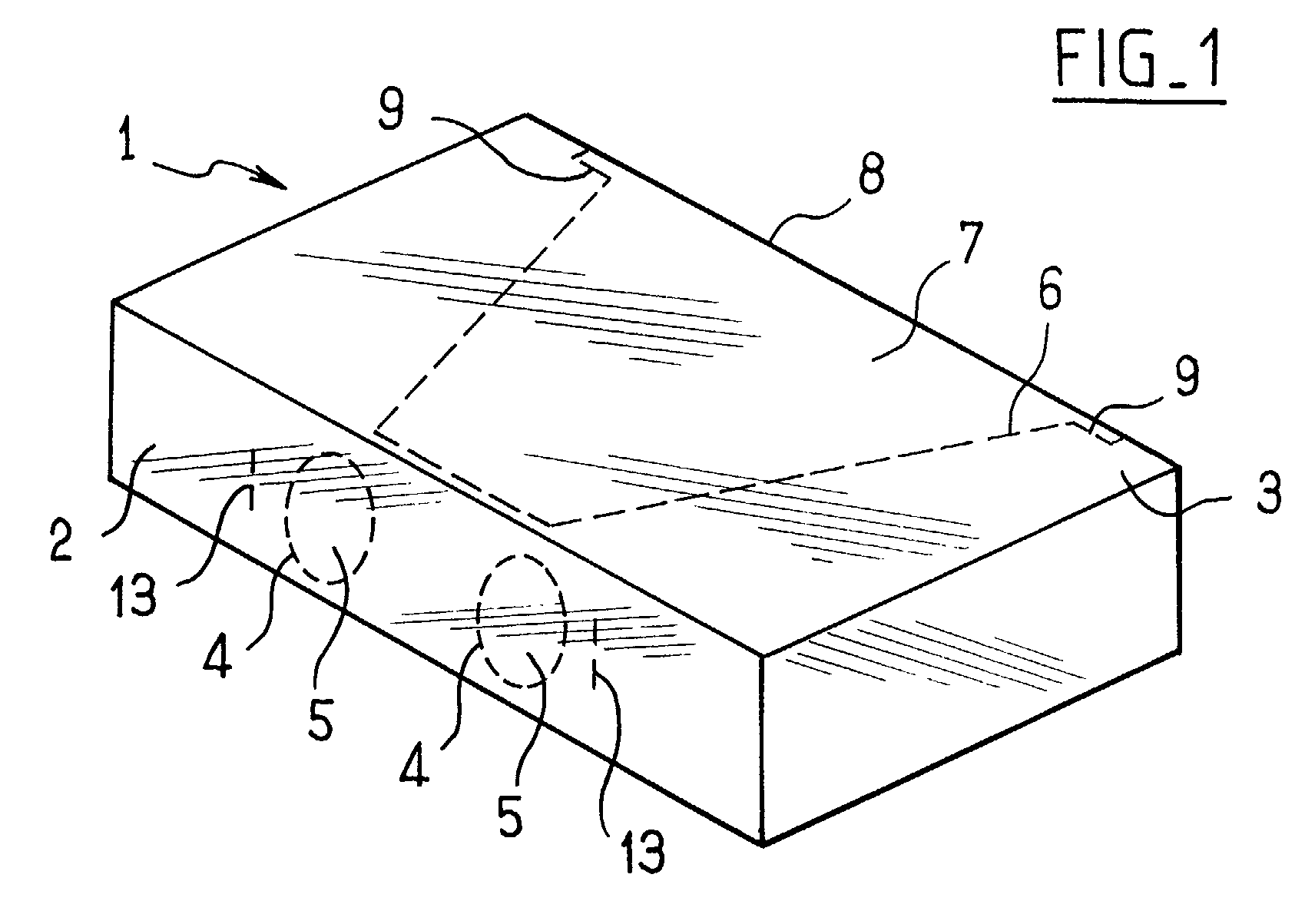
- a parallelepiped box formed in a manner known per se from a blank, has a front wall 2 and an upper wall 3 adjacent to the front wall 2.
- the front wall 2 includes pre-cuts 4 illustrated in dotted lines defining portions detachable 5 here of substantially circular shape.
- the upper wall 3 comprises a precut 6 defining a folding flap 7 whose hinge is constituted by an edge 8 of the box 1 parallel at the front wall 2.
- precuts 9 of the upper wall 3 extending parallel to the edge 8 in the vicinity thereof defines, after detachment flap 7, two slots 10 (better visible on the Figure 2) extending on either side of the flap 7.
- Box 1 is transformed into a viewer by detaching portions 5 of the front wall, and by detaching the flap 7 and the slots 10, as illustrated in Figure 2.
- the detached portions 5 define orifices from the front wall 2 distant from an eye spacing allowing binocular vision inward of the box, while the flap 7 folded on the one hand an access for the surrounding light inside the box, and secondly access to a support wall 11 for a double image 12, the support wall 11 here being constituted by the rear wall of the box 1 opposite the wall front 2 which is, by construction of the box, away from said front wall.
- 10 slots organize a slide system for reliable support of the double image 12 on the support wall 11, with a view to observation of the double image by binocular vision, with the well-known effect of stereoscopic viewers.
- a binocular magnifier 100 is attached to the wall front 2.
- the front wall 2 is provided 13 parallel pre-cuts, arranged on each side detachable portions 5.
- the magnifying glass 100 includes two circular lenses 101 interconnected by a flexible ligament 102, each lenses 101 carrying a projecting tab 103.
- Figure 8 illustrates how to set up the binocular magnifying glass 100 on the front wall of the box 1.
- the precuts 13 are detached, defining two slots 14.
- the ligament 102 of the binocular loupe 100 is then bent so as to introduce the legs 103 into the slots 14. By resuming its form of rest, the ligament prevents legs 103 come out of the slots 14, keeping it in place being provided by the inherent elasticity of the ligament 102, of so the magnifying glass is securely attached to the front wall 2.
- the slit system 14 may not be used.
- the box 1 is thus easily transformed into a stereoscopic viewer, without the need to glue or staple. It is the user can change the double image at will.
- the binocular magnifier can be inserted into the box when filled, or packed in a sachet plastic glued to the box, so that the user will only have to install it according to the method described.
- a parallelepiped box 21 has a front wall 22 and an upper wall 23 adjacent to the wall 21.
- the front wall 21 comprises pre-cuts 24 defining detachable portions 25 again circular.
- the wall upper 23 has a precut 26 defining two folding flaps 27 extending between the front wall 22 and the rear wall of the box 31 (not visible here) opposite of the front wall 22.
- the flaps 27 are separated by a central precut 28 extending perpendicularly to the front wall 22, and are delimited by a line folding 29 extending parallel to the precut 28.
- Folding lines 30 parallel to the precut 28 define on each flap 27 two panels 32 and 33 as illustrated in figure 4.
- the box 21 is transformed into a viewer by detaching the portions 25 from the front wall 22, and by detaching the flaps 27.
- the flaps 27 are folded down so that the panel 32 assume an almost vertical position and that the panel 33 take a horizontal position at the bottom of the box.
- the detached portions define orifices from the front wall 22 distant from an eye spacing to allow binocular vision inward of the box.
- a binocular magnifier 100 is attached to the front wall 22 similarly to what has already been described.
- the front wall 22 is there again provided with parallel precuts 13 on each side of the detachable portions 25.
- the folded flaps 27 allow on the one hand access for the surrounding light inside the box, and secondly access to a support wall 31 for a double image 12, the support wall 31 being as before consisting of the wall of the box 21 opposite the front wall 22.
- the panels 32 organize with the support wall 31 a slide system capable of receiving and allowing the maintenance of the double image 12 against the wall 31. This provision also has the advantage to stiffen the box thus cut.
- a slide system comprising two notches 35 extending perpendicularly to the hinges 29 to cut the flaps 27 in half parts and bite slightly beyond the hinges 29 on the upper face 23.
- This slide system plays here the role of the dual 12 image support means, in addition to its role in guiding said double image.
- the invention is suitable for a box whose distance between the front wall and the opposite rear wall from the front wall is greater than the distance focal length of the magnifying lenses.
- Box 41 illustrated here transformed into a viewer comprises a front wall 42 having two orifices to allow binocular vision inward of the box.
- the two orifices are obtained as in the previous embodiments by detaching portions of the front walls defined by precuts.
- the length L of the box 41 is here notably greater than the focal length F of the binocular loupe, so it is not possible to use of the rear wall of the box 41 as a support means for a double image.
- two flaps 47 are then provided. on the upper wall 43 of the box 41 similar to those described in relation to Figures 3 and 4, but not extending to the rear wall of the box 41, but only up to a distance substantially equal to the focal length F of the binocular loupe.
- These shutters 47 are folded down along fold lines 49 while being as before obtained from pre-cuts made on the upper wall 43.
- the flaps 47 are shown in the folded position in FIG. 6.
- the detachment of the two flaps 47 makes it appear a free edge 48 of the upper wall 43 extending parallel at the front wall 42.
- the detachable element 46 has a portion of edge 52 secant with the portion of edge 48 remaining untouched when the detachable element 46 is detached.
- the edge 48 and the edge portion 52 of the detachable element 46 define a support plane 51 facing the front wall 42 for a double 12 image sketched in mixed lines on Figure 6.
- the support plane is substantially parallel to the front wall 42 and is located at a distance F substantially equal to the focal length F of the binocular magnifier used.
- the flaps 47 allow access for the surrounding light inside the box 41 in sight to illuminate the double image 12, and organize as before a slide system for guiding the image double 12 on the support plane thus defined.
- a binocular magnifier 100 is also reported on the front wall 42 similarly to what has already been described.
- the front wall 42 is provided with parallel precuts 13 for positioning of the binocular magnifier 100.
Landscapes
- Physics & Mathematics (AREA)
- General Physics & Mathematics (AREA)
- Optics & Photonics (AREA)
- Stereoscopic And Panoramic Photography (AREA)
Abstract
L'invention concerne une boíte transformable ayant
une paroi frontale et des parois adjacentes à la paroi
frontale, certaines au moins de ces parois comportant des
prédécoupes délimitant des éléments de paroi partiellement
ou totalement détachables. Selon l'invention, la paroi
frontale (2) comporte un élément détachable (5) permettant,
après détachement, une vision binoculaire à l'intérieur de
la boíte, l'une des parois adjacentes (3) à la paroi frontale
comportant un élément détachable (7) permettant, après
détachement, un accès pour la lumière environnante à
l'intérieur de la boíte, un moyen de support étant en outre
agencé à l'intérieur de la boíte à distance de la paroi
frontale (2) pour supporter une image double en regard de
ladite la paroi frontale à distance de celle-ci.
Description
L'invention concerne une boíte transformable en visionneuse stéréoscopique. L'invention concerne notamment mais pas exclusivement des boítes en carton utilisées pour le conditionnement alimentaire.The invention relates to a box convertible into a viewer stereoscopic. The invention relates in particular to but not exclusively cardboard boxes used for food packaging.
On connaít, par exemple du document FR-A-2789769, des visionneuses stéréoscopiques formées par un flan prédécoupé définissant une structure pliable, cette structure comprenant une paroi d'appui pour une image double et une paroi de vision binoculaire en regard de la paroi d'appui, les deux parois étant reliées par des liens pliables de sorte que la visionneuse est stockable à plat. Un tel flan est d'un usage très spécifique, et ne peut en aucun cas servir à une autre application.We know, for example from document FR-A-2789769, stereoscopic viewers formed by a precut blank defining a foldable structure, this structure including a support wall for a double image and a binocular vision wall opposite the support wall, the two walls being connected by foldable links of so the viewer can be stored flat. Such a blank is for a very specific use, and can in no case be used for another application.
Considérant d'une part l'énorme quantité de boítes en carton produites, le plus souvent jetées une fois vidées de leur contenu, et d'autre part l'attrait ludique qu'offrent les dispositifs stéréoscopiques, il paraít intéressant d'un point de vue économique et publicitaire d'offrir la possibilité de transformer de façon simple une telle boíte en une visionneuse stéréoscopique, la transformation ne devant faire appel à aucun outil ni moyen de liaison de type colle ou agrafes.Considering on the one hand the huge amount of boxes made of cardboard, most often discarded once emptied of their content, and on the other hand the playful appeal that stereoscopic devices offer, it seems interesting from an economic and advertising point of view to offer the possibility of transforming in a simple way a such box in a stereoscopic viewer, the transformation not having to use any tool or means of glue or staple type binding.
A cet effet, on prévoit une boíte transformable ayant une paroi frontale et des parois adjacentes à la paroi frontale, certaines au moins de ces parois comportant des prédécoupes délimitant des éléments de paroi partiellement ou totalement détachables. Selon l'invention, la paroi frontale comporte au moins un élément détachable permettant, après détachement, une vision binoculaire à l'intérieur de la boíte, et au moins l'une des parois adjacentes à la paroi frontale comporte au moins un élément détachable permettant, après détachement, un accès pour la lumière environnante à l'intérieur de la boíte, un moyen de support étant en outre agencé à l'intérieur de la boíte à distance de la paroi frontale pour supporter une image double en regard de la paroi frontale à distance de celle-ci.For this purpose, a transformable box is provided having a front wall and walls adjacent to the wall frontal, at least some of these walls comprising pre-cuts delimiting partially wall elements or fully detachable. According to the invention, the wall front has at least one detachable element allowing, after detachment, binocular vision at the inside of the box, and at least one of the adjacent walls at the front wall has at least one detachable element allowing, after detachment, access for the surrounding light inside the box, a way to support being further arranged inside the box distance from the front wall to support a double image opposite the front wall at a distance therefrom.
Ainsi, lorsque les éléments détachables ne sont pas détachés, la boíte assure sa fonction première de contenant, et lorsque les éléments détachables sont détachés, la boíte est transformée en une visionneuse qui, en rapportant une loupe binoculaire sur la première paroi, permet la vision stéréoscopique d'une image double disposée sur ou contre le moyen de support.So when the detachable items are not detached, the box performs its primary function as a container, and when the detachable elements are detached, the box is transformed into a viewer which, by reporting a binocular magnifier on the first wall, allows vision stereoscopic of a double image arranged on or against the support means.
De préférence, l'élément détachable de la première paroi comporte deux portions distantes d'un écartement oculaire. On peut ainsi adapter de façon adéquate une loupe binoculaire présentant deux lentilles circulaires.Preferably, the detachable element of the first wall has two portions spaced apart from one eye. We can thus adequately adapt a magnifying glass binocular with two circular lenses.
De préférence encore, la paroi frontale comporte deux prédécoupes réalisées de part et d'autre de l'élément détachable de la paroi frontale, ces prédécoupes formant, après détachement, des fentes pour la mise en place d'une optique binoculaire.More preferably, the front wall has two pre-cuts made on either side of the element detachable from the front wall, these pre-cuts forming, after detachment, slots for the installation of a binocular optics.
Selon un premier mode de réalisation, une paroi adjacente à la paroi frontale comporte un élément détachable ayant une ligne de pliage s'étendant le long d'une paroi arrière de la boíte en regard de la paroi frontale, la paroi arrière constituant, après détachement, le moyen de support de l'image double.According to a first embodiment, an adjacent wall at the front wall has a detachable element having a fold line extending along a wall back of the box opposite the front wall, the wall rear constituting, after detachment, the means of dual image support.
Ainsi, l'élément détachable permet tout à la fois l'accès à la paroi arrière servant de support à l'image double et l'accès à la lumière environnante vers ladite paroi arrière. L'élément détachable peut alors être laissé dans une position parallèle à la face arrière pour aider au support de l'image double.Thus, the detachable element allows everything at the same time access to the rear wall used to support the image double and access to the surrounding light towards said wall back. The detachable element can then be left in a position parallel to the back side to help dual image support.
Avantageusement alors, la paroi adjacente à la paroi frontale comprend en outre deux prédécoupes s'étendant de part et d'autre de l'élément détachable le long de la paroi arrière au voisinage de celle-ci, ces prédécoupes constituant après détachement un système de glissière apte à recevoir l'image double. Advantageously then, the wall adjacent to the wall front also includes two pre-cuts extending on either side of the detachable element along the rear wall in the vicinity thereof, these precuts constituting after detachment a suitable slide system to receive the double image.
Ce système de glissière facilite la mise en place de l'image double et stabilise celle-ci contre la paroi arrière.This slide system facilitates installation of the double image and stabilizes it against the rear wall.
Selon un deuxième mode de réalisation de l'invention, une paroi adjacente à la paroi frontale comporte un élément détachable délimité par une prédécoupe dont une portion arrière s'étend le long d'une paroi arrière de la boíte en regard de la paroi frontale, la paroi arrière constituant, après détachement de la prédécoupe, le moyen de support de l'image double.According to a second embodiment of the invention, a wall adjacent to the front wall comprises a detachable element delimited by a precut a rear portion of which extends along a rear wall of the box opposite the front wall, the wall rear component, after detachment of the precut, the dual image support means.
De préférence alors, l'élément détachable est composé de deux volets s'étendant jusqu'à la paroi arrière et ayant chacun une ligne de pliage s'étendant perpendiculairement à la paroi arrière, les volets en position rabattue dans la boíte et la face arrière définissant après détachement un système de glissière apte à recevoir l'image double.Preferably then, the detachable element is composed two flaps extending to the rear wall and each having a fold line extending perpendicularly at the rear wall, the flaps in the folded position in the box and the back defining after detachment a slide system capable of receiving the double image.
Selon une variante de réalisation, des encoches s'étendent parallèlement à la paroi frontale à cheval sur les lignes de pliage de chacun des volets pour constituer, après détachement, le moyen de support de l'image double lorsque les volets sont rabattus.According to an alternative embodiment, notches extend parallel to the front wall straddling the fold lines of each of the flaps to constitute, after detachment, the means for supporting the double image when the flaps are folded down.
On peut alors positionner l'image double à une distance de la paroi frontale qui est inférieure à la distance entre la paroi frontale et la paroi arrière, en vue de positionner l'image double à une distance sensiblement égale à la distance focale de la loupe binoculaire rapportée sur la paroi frontale.We can then position the double image at a distance from the front wall which is less than the distance between the front wall and the rear wall, in order to position the image doubles at a substantially equal distance at the focal length of the binocular magnifier reported on the front wall.
Selon un troisième mode de réalisation, une paroi adjacente à la paroi frontale comporte un premier élément détachable délimité par une prédécoupe dont une portion arrière s'étend parallèlement à la paroi frontale pour définir un bord d'appui après détachement du premier élément détachable, la même paroi adjacente comportant en outre un second élément détachable s'étendant jusqu'au bord d'appui et ayant une ligne de pliage perpendiculaire à ce bord d'appui, le bord d'appui et le second élément en position rabattue autour de la ligne de pliage constituant, après détachement, le moyen de support de l'image double.According to a third embodiment, a wall adjacent to the front wall has a first element detachable delimited by a precut including a rear portion extends parallel to the front wall to define a support edge after detachment of the first element detachable, the same adjacent wall further comprising a second detachable element extending to the support edge and having a fold line perpendicular to this edge support, the support edge and the second element in position folded around the fold line constituting, after detachment, the means of supporting the double image.
Le moyen de support peut là encore être positionné à une distance arbitraire de la paroi frontale, inférieure à la distance délimitée entre la paroi frontale et la paroi arrière de la boíte.The support means can again be positioned at an arbitrary distance from the front wall, lower at the distance between the front wall and the wall back of the box.
Avantageusement alors, le premier élément détachable est composé de deux volets s'étendant jusqu'au moyen de support et ayant chacun une ligne de pliage s'étendant perpendiculairement au bord libre, les volets en position rabattue dans la boíte et le bord libre définissant, après détachement, un système de glissière apte à recevoir l'image double.Advantageously then, the first detachable element is made up of two parts extending up to support and each having a fold line extending perpendicularly at the free edge, the flaps in the folded position in the box and the free edge defining, after detachment, a slide system capable of receiving the double image.
D'autres caractéristiques et avantages de l'invention apparaítront plus clairement à la lumière de la description qui suit de modes de réalisation particuliers non limitatifs de l'invention. Il sera fait référence aux dessins annexés et aux figures parmi lesquelles :
- la figure 1 est une vue en perspective d'une première boíte selon l'invention ;
- la figure 2 est une vue en perspective de la première boíte selon l'invention, transformée en visionneuse stéréoscopique ;
- la figure 3 est une vue en perspective d'une deuxième boíte selon l'invention ;
- la figure 4 est une vue en perspective de la deuxième boíte selon l'invention, transformée en visionneuse stéréoscopique ;
- la figure 5 est une vue en perspective d'une variante de réalisation de la boíte précédente ;
- la figure 6 est une vue en perspective d'une troisième boíte selon l'invention, transformée en visionneuse stéréoscopique ;
- la figure 7 est une vue de face d'une loupe binoculaire adaptable aux boítes précédentes ;
- la figure 8 est une vue en coupe partielle d'une boíte selon l'invention ainsi que de la loupe en cours d'installation sur la boíte.
- Figure 1 is a perspective view of a first box according to the invention;
- Figure 2 is a perspective view of the first box according to the invention, transformed into a stereoscopic viewer;
- Figure 3 is a perspective view of a second box according to the invention;
- Figure 4 is a perspective view of the second box according to the invention, transformed into a stereoscopic viewer;
- Figure 5 is a perspective view of an alternative embodiment of the previous box;
- Figure 6 is a perspective view of a third box according to the invention, transformed into a stereoscopic viewer;
- Figure 7 is a front view of a binocular loupe adaptable to previous boxes;
- Figure 8 is a partial sectional view of a box according to the invention and of the magnifying glass being installed on the box.
Il convient avant toutes choses de noter que les termes de direction inférieure, supérieure, horizontale, verticale, avant, arrière, utilisés ici font tous référence à un sens d'utilisation de la boíte comme visionneuse tel que représenté sur les figures, sans que les termes utilisés désignent des parois préférées ou particulières de la boíte.Above all, it should be noted that terms of lower, upper, horizontal direction, vertical, front, rear, used here all refer to a sense of using the box as a viewer such as shown in the figures, without the terms used denote preferred or particular walls of the box.
En référence à la figure 1 illustrant un premier
mode de réalisation de l'invention, une boíte parallélépipédique
1, formée de manière connue en soi à partir d'un
flan, comporte une paroi frontale 2 et une paroi supérieure
3 adjacente à la paroi frontale 2.Referring to Figure 1 illustrating a first
embodiment of the invention, a
Selon l'invention, la paroi frontale 2 comporte des
prédécoupes 4 illustrées en pointillés définissant des portions
détachables 5 ici de forme sensiblement circulaire.
Toujours selon l'invention, la paroi supérieure 3 comporte
une prédécoupe 6 définissant un volet rabattable 7 dont la
charnière est constituée par une arête 8 de la boíte 1 parallèle
à la paroi frontale 2. Par ailleurs, des prédécoupes
9 de la paroi supérieure 3 s'étendant parallèlement à
l'arête 8 au voisinage de celle-ci définissent, après détachement
du volet 7, deux fentes 10 (mieux visibles sur la
figure 2) s'étendant de part et d'autre du volet 7.According to the invention, the
La boíte 1 est transformée en visionneuse en détachant
les portions 5 de la paroi frontale, et en détachant
le volet 7 et les fentes 10, ainsi que cela est illustrée à
la figure 2. Les portions 5 détachées définissent des orifices
de la paroi frontale 2 distants d'un écartement oculaire
permettant la vision binoculaire vers l'intérieur de
la boíte, tandis que le volet 7 rabattu permet d'une part
un accès pour la lumière environnante à l'intérieur de la
boíte, et d'autre part un accès à une paroi d'appui 11 pour
une image double 12, la paroi d'appui 11 étant ici constituée
par la paroi arrière de la boíte 1 en regard de la paroi
frontale 2 qui se trouve, par construction de la boíte,
à distance de ladite paroi frontale. Les fentes 10 organisent
un système de glissière permettant le maintien fiable
de l'image double 12 sur la paroi d'appui 11, en vue de
l'observation de l'image double par vision binoculaire,
avec l'effet bien connu des visionneuses stéréoscopiques.
Une loupe binoculaire 100 est rapportée sur la paroi
frontale 2. A cet effet, la paroi frontale 2 est pourvue
de prédécoupes 13 parallèles, disposées de chaque côté
des portions détachables 5. Ainsi que cela est visible à la
figure 7, la loupe 100 comprend deux lentilles circulaires
101 reliées entre elles par un ligament flexible 102, chacune
des lentilles 101 portant une patte saillante 103.A
La figure 8 illustre la façon de mettre en place la
loupe binoculaire 100 sur la paroi frontale de la boíte 1.
Les prédécoupes 13 sont détachées, définissant deux fentes
14. Le ligament 102 de la loupe binoculaire 100 est alors
fléchi de façon à introduire les pattes 103 dans les fentes
14. En reprenant sa forme de repos, le ligament empêche les
pattes 103 de sortir des fentes 14, le maintien en place
étant assuré par l'élasticité propre du ligament 102, de
sorte que la loupe est solidement attachée à la paroi frontale
2.Figure 8 illustrates how to set up the
binocular
En variante non représentée, le système de fentes
14 peut ne pas être utilisé. En veillant à réaliser les
prédécoupes 4 de sorte que la distance entre les éléments
détachables 5 soit légèrement inférieure à la distance entre
les lentilles 101, on conçoit alors que la mise en
place de la loupe binoculaire 100 exige une légère flexion
du ligament 102 afin que les lentilles 101 entrent dans les
orifices obtenus par détachement des éléments détachables
5. Cette légère flexion va induire un appui élastique des
lentilles 101 contre les bords externes desdits orifices,
cet appui contribuant au maintien de la loupe 100 sur la
visionneuse. Les pattes 103 servent alors de butée anti-extraction.In a variant not shown, the
La boíte 1 est ainsi facilement transformée en une
visionneuse stéréoscopique, sans qu'il soit nécessaire de
procéder à une opération de collage ou d'agrafage. Il est
loisible à l'utilisateur de changer d'image double à volonté.
La loupe binoculaire pourra être introduite dans la
boíte au moment de son remplissage, ou emballée dans un sachet
plastique collé à la boíte, de sorte que l'utilisateur
n'aura plus qu'à l'installer selon la méthode décrite.The
Selon une variante non représentée, on pourra imprimer
directement une image double sur la paroi arrière 11
de la boíte, l'image double pouvant éventuellement déborder
sur la face interne du volet 7. On pourra encore imprimer
une image double sur la face externe du volet 7, une série
de lignes de pliage réalisées sur le volet 7 permettant
alors de rabattre la face externe du volet 7 à l'intérieur
de la boíte contre la paroi arrière 11 de façon que cette
image double se trouve en regard de la paroi frontale 2.According to a variant not shown, it will be possible to print
directly a double image on the
Selon un deuxième mode de réalisation de
l'invention illustré à la figure 3, une boíte parallélépipédique
21 comporte une paroi frontale 22 et une paroi supérieure
23 adjacente à la paroi 21.According to a second embodiment of
the invention illustrated in Figure 3, a
Selon l'invention, la paroi frontale 21 comporte
des prédécoupes 24 définissant des portions détachables 25
là encore circulaires. Toujours selon l'invention, la paroi
supérieure 23 comporte une prédécoupe 26 définissant deux
volets rabattables 27 s'étendant entre la paroi frontale 22
et la paroi arrière de la boíte 31 (non visible ici) en regard
de la paroi frontale 22. Les volets 27 sont séparés
par une prédécoupe centrale 28 s'étendant perpendiculairement
à la paroi frontale 22, et sont délimités par une ligne
de pliage 29 s'étendant parallèlement à la prédécoupe
28. Des lignes de pliage 30 parallèles à la prédécoupe 28
définissent sur chaque volet 27 deux panneaux 32 et 33
comme illustré sur la figure 4.According to the invention, the
Ainsi que cela est visible à la figure 4, la boíte
21 est transformée en visionneuse en détachant les portions
25 de la paroi frontale 22, et en détachant les volets 27.
Les volets 27 sont rabattus de façon que le panneau 32
prenne une position quasi verticale et que le panneau 33
prenne une position horizontale en fond de boíte.As can be seen in Figure 4, the
Les portions 25 détachées définissent des orifices
de la paroi frontale 22 distants d'un écartement oculaire
pour permettre une vision binoculaire vers l'intérieur de
la boíte. Une loupe binoculaire 100 est rapportée sur la
paroi frontale 22 de manière similaire à ce qui a déjà été
décrit. A cet effet, la paroi frontale 22 est là encore
pourvue de prédécoupes parallèles 13 de chaque côté des
portions détachables 25.The detached portions define orifices
from the
Les volets 27 rabattus permettent d'une part
l'accès pour la lumière environnante à l'intérieur de la
boíte, et d'autre part l'accès à une paroi d'appui 31 pour
une image double 12, la paroi d'appui 31 étant comme précédemment
constituée de la paroi de la boíte 21 en regard de
la paroi frontale 22. Les panneaux 32 organisent avec la
paroi d'appui 31 un système de glissière apte à recevoir et
permettant le maintien de l'image double 12 contre la paroi
d'appui 31. Cette disposition présente en outre l'avantage
de rigidifier la boíte ainsi découpée.The folded flaps 27 allow on the one hand
access for the surrounding light inside the
box, and secondly access to a
Selon une variante illustrée à la figure 5 sur
laquelle les éléments communs avec ceux des figures 3 et 4
portent la même référence, on prévoit un système de glissière
comprenant deux encoches 35 s'étendant perpendiculairement
aux charnières 29 pour couper les volets 27 en deux
parties et mordre légèrement au delà des charnières 29 sur
la face supérieure 23. Ce système de glissière joue ici le
rôle du moyen de support de l'image double 12, en plus de
son rôle de guidage de ladite image double.According to a variant illustrated in FIG. 5 on
which the elements common with those of Figures 3 and 4
bear the same reference, a slide system is provided
comprising two
Selon un troisième mode de réalisation illustré à la figure 6, l'invention est adaptée à une boíte dont la distance entre la paroi frontale et la paroi arrière en regard de la paroi frontale est plus grande que la distance focale des lentilles de la loupe.According to a third embodiment illustrated in Figure 6, the invention is suitable for a box whose distance between the front wall and the opposite rear wall from the front wall is greater than the distance focal length of the magnifying lenses.
La boíte 41 illustrée ici transformée en visionneuse
comprend une paroi frontale 42 présentant deux orifices
pour permettre la vision binoculaire vers l'intérieur
de la boíte. Les deux orifices sont obtenus comme dans les
modes de réalisation précédents par détachement de portions
de la paroi frontales définis par des prédécoupes.
La longueur L de la boíte 41 est ici notablement
plus grande que la distance focale F de la loupe binoculaire,
de sorte qu'il n'est pas envisageable de se servir
de la paroi arrière de la boíte 41 comme d'un moyen de support
pour une image double.The length L of the
Selon l'invention, on prévoit alors deux volets 47
sur la paroi supérieure 43 de la boíte 41 similaires à ceux
décrits en relation avec les figures 3 et 4, mais
s'étendant non pas jusqu'à la paroi arrière de la boíte 41,
mais uniquement jusqu'à une distance sensiblement égale à
la distance focale F de la loupe binoculaire. Ces volets 47
sont rabattus le long de lignes de pliage 49 en étant
comme auparavant obtenus à partir de prédécoupes réalisées
sur la paroi supérieure 43. Les volets 47 sont représentés
en position rabattue sur la figure 6.According to the invention, two
Le détachement des deux volets 47 fait apparaítre
un bord libre 48 de la paroi supérieure 43 s'étendant parallèlement
à la paroi frontale 42. Une autre prédécoupe 44
s'étendant jusqu'à ce bord 48, et rejoignant une ligne
pliable 45 s'étendant perpendiculairement au bord 48, définit
un élément détachable 46 que l'on voit ici rabattu vers
l'intérieur de la boíte 41. The detachment of the two
L'élément détachable 46 présente une portion de
bord 52 sécante avec la partie du bord 48 restée intouchée
lors du détachement de l'élément détachable 46. Le bord 48
et la portion de bord 52 de l'élément détachable 46 définissent
un plan d'appui 51 en regard de la paroi frontale
42 pour une image double 12 esquissée en traits mixtes sur
la figure 6. Le plan d'appui est sensiblement parallèle à
la paroi frontale 42 et est situé à une distance F sensiblement
égale à la distance focale F de la loupe binoculaire
utilisée. Les volets 47 permettent un accès pour la
lumière environnante à l'intérieur de la boíte 41 en vue
d'éclairer l'image double 12, et organisent comme précédemment
un système de glissière pour le guidage de l'image
double 12 sur le plan d'appui ainsi défini.The
Une loupe binoculaire 100 est en outre rapportée
sur la paroi frontale 42 de manière similaire à ce qui a
déjà été décrit. A cet effet, la paroi frontale 42 est
pourvue de prédécoupes parallèles 13 pour la mise en place
de la loupe binoculaire 100.A
L'invention n'est pas limitée aux modes particuliers de réalisation qui viennent d'être décrits, mais bien au contraire entend couvrir toute variante qui entre dans le cadre de l'invention tel que défini par les revendications.The invention is not limited to particular modes which have just been described, but on the contrary intends to cover any variant which enters the scope of the invention as defined by the claims.
Bien que l'on ait décrit ici des modes de réalisation de l'invention pour lesquels l'image double est rapportée, on peut envisager, pour les boítes présentant une paroi d'appui en guise de moyen de support, qu'une image double soit imprimée directement sur la paroi d'appui.Although embodiments have been described here of the invention for which the double image is reported, we can consider, for boxes with a support wall as a means of support, that an image double is printed directly on the support wall.
Enfin, bien que l'on ait décrit ici des boítes dont les portions détachables de la paroi adjacente à la paroi frontale servaient à la fois d'accès au moyen de support et d'accès à la lumière environnante à l'intérieur de la boíte, on peut envisager de séparer ces deux accès, lesdits deux accès pouvant être réalisées sur des parois différentes.Finally, although we have described here boxes which the detachable portions of the wall adjacent to the wall front were used both to access the support means and access to the surrounding light inside the box, we can consider separating these two accesses, said two accesses can be made on different walls.
Claims (10)
Applications Claiming Priority (2)
| Application Number | Priority Date | Filing Date | Title |
|---|---|---|---|
| FR0103000 | 2001-03-06 | ||
| FR0103000A FR2821938B1 (en) | 2001-03-06 | 2001-03-06 | BOX CONVERTIBLE INTO STEREOSCOPIC VIEWER |
Publications (2)
| Publication Number | Publication Date |
|---|---|
| EP1255152A2 true EP1255152A2 (en) | 2002-11-06 |
| EP1255152A3 EP1255152A3 (en) | 2002-11-13 |
Family
ID=8860765
Family Applications (1)
| Application Number | Title | Priority Date | Filing Date |
|---|---|---|---|
| EP02290548A Withdrawn EP1255152A3 (en) | 2001-03-06 | 2002-03-06 | Box transformable in a stereoscopic viewing system |
Country Status (2)
| Country | Link |
|---|---|
| EP (1) | EP1255152A3 (en) |
| FR (1) | FR2821938B1 (en) |
Cited By (1)
| Publication number | Priority date | Publication date | Assignee | Title |
|---|---|---|---|---|
| DE102007036339A1 (en) * | 2007-08-02 | 2009-02-05 | Jörn Garbade | Stereoscope comprises box with central partition which divides it into two channels with apertures for mounting lenses at one end and mountings for stereoscopic images at other |
Families Citing this family (1)
| Publication number | Priority date | Publication date | Assignee | Title |
|---|---|---|---|---|
| FR2989473B1 (en) | 2012-04-13 | 2014-04-25 | Philippe Sagniez | FOLDING 3D VIEWER. |
Family Cites Families (4)
| Publication number | Priority date | Publication date | Assignee | Title |
|---|---|---|---|---|
| CH425268A (en) * | 1965-07-29 | 1966-11-30 | Nakatani Koma | Collapsible viewer for stereo head images |
| US3734596A (en) * | 1971-03-24 | 1973-05-22 | Dimensional Production Ltd | Viewer |
| US5058991A (en) * | 1989-04-10 | 1991-10-22 | Curtin James J | Mailable 3-D viewers of post card size |
| FR2729233A1 (en) * | 1995-01-10 | 1996-07-12 | Thillard Dominique | Stereoscopic image viewer |
-
2001
- 2001-03-06 FR FR0103000A patent/FR2821938B1/en not_active Expired - Fee Related
-
2002
- 2002-03-06 EP EP02290548A patent/EP1255152A3/en not_active Withdrawn
Cited By (1)
| Publication number | Priority date | Publication date | Assignee | Title |
|---|---|---|---|---|
| DE102007036339A1 (en) * | 2007-08-02 | 2009-02-05 | Jörn Garbade | Stereoscope comprises box with central partition which divides it into two channels with apertures for mounting lenses at one end and mountings for stereoscopic images at other |
Also Published As
| Publication number | Publication date |
|---|---|
| FR2821938A1 (en) | 2002-09-13 |
| EP1255152A3 (en) | 2002-11-13 |
| FR2821938B1 (en) | 2003-06-20 |
Similar Documents
| Publication | Publication Date | Title |
|---|---|---|
| EP0312669A1 (en) | Container provided with a retractable panel, blank for the container and medicine tablets with the container | |
| FR2731685A3 (en) | PACKED ELECTRIC LAMP | |
| EP1255152A2 (en) | Box transformable in a stereoscopic viewing system | |
| FR2610596A1 (en) | Package with handle | |
| EP0665167B1 (en) | Box comprising outer walls and internal supporting element | |
| FR3050441A3 (en) | PACKAGING IN CARDBOARD FOR CONTAINING BOTTLES OR CANALS, DESIGNED TO FORM A CALENDAR OF ADVENT | |
| FR2789051A1 (en) | Packaging for display and storage of food products, comprises a tray including a sealing flap mounted within a sheath | |
| FR2703663A1 (en) | Packaging case | |
| FR2931803A1 (en) | Carrying case for packaging and protection of e.g. bottles, has separating shutters cut into set of lateral panels of envelope to push back towards interior of envelope for delimiting compartments to receive products to be packaged | |
| EP0082448A1 (en) | Box | |
| FR2884809A1 (en) | Article extraction and protection device for e.g. flask, has support unit with end parts defining central part which extends along opposite walls and base wall so that free end part is arranged near upper part of body opposite to base wall | |
| FR2693984A1 (en) | Dismantlable storage tray - has bottom, rear and front walls formed from single flexible angled piece with clip on identical rigid side walls | |
| EP2274209A1 (en) | Rigid packet designed to contain small items | |
| FR2718716A1 (en) | Semi=rigid packaging for bottles | |
| FR2542709A1 (en) | Box in the shape of a truncated pyramid | |
| WO2012010756A1 (en) | Tray, the rigidity of which is improved, for transporting and displaying items such as cups of yogurt | |
| FR2859190A1 (en) | Electrical battery reception device for e.g. watch, has drawer allowing selective access to compartment to extract new battery, and tab allowing used battery insertion and separating new and used batteries | |
| FR2772723A1 (en) | Packaging container for bottle | |
| FR2714188A1 (en) | Deployable stereoscope. | |
| FR3056196B1 (en) | DEVICE FOR PACKAGING A PRODUCT. | |
| FR2875218A1 (en) | PLATE FOR BAG PRODUCTS | |
| EP0014137A1 (en) | Pocket-case for documentary, touristic, publicity or similar uses | |
| FR2794103A1 (en) | Semi rigid packaging box has interchangeable top and bottom comprising identical polygonal panel | |
| FR2752564A1 (en) | PACKAGING POUCH FOR PHOTOGRAPHIC WORKS | |
| CA1221859A (en) | Apparatus for viewing a series of stereoscopic images arranged by pairs on a medium to form a stereocard |
Legal Events
| Date | Code | Title | Description |
|---|---|---|---|
| PUAI | Public reference made under article 153(3) epc to a published international application that has entered the european phase |
Free format text: ORIGINAL CODE: 0009012 |
|
| PUAL | Search report despatched |
Free format text: ORIGINAL CODE: 0009013 |
|
| AK | Designated contracting states |
Kind code of ref document: A2 Designated state(s): AT BE CH CY DE DK ES FI FR GB GR IE IT LI LU MC NL PT SE TR |
|
| AX | Request for extension of the european patent |
Free format text: AL;LT;LV;MK;RO;SI |
|
| AK | Designated contracting states |
Kind code of ref document: A3 Designated state(s): AT BE CH CY DE DK ES FI FR GB GR IE IT LI LU MC NL PT SE TR |
|
| AX | Request for extension of the european patent |
Free format text: AL;LT;LV;MK;RO;SI |
|
| AKX | Designation fees paid | ||
| REG | Reference to a national code |
Ref country code: DE Ref legal event code: 8566 |
|
| STAA | Information on the status of an ep patent application or granted ep patent |
Free format text: STATUS: THE APPLICATION IS DEEMED TO BE WITHDRAWN |
|
| 18D | Application deemed to be withdrawn |
Effective date: 20030514 |