EP1255060B1 - Reducteur epicycloidal et mecanisme de manoeuvre d'une installation de fermeture de protection solaire comprenant un tel reducteur - Google Patents
Reducteur epicycloidal et mecanisme de manoeuvre d'une installation de fermeture de protection solaire comprenant un tel reducteur Download PDFInfo
- Publication number
- EP1255060B1 EP1255060B1 EP02356084A EP02356084A EP1255060B1 EP 1255060 B1 EP1255060 B1 EP 1255060B1 EP 02356084 A EP02356084 A EP 02356084A EP 02356084 A EP02356084 A EP 02356084A EP 1255060 B1 EP1255060 B1 EP 1255060B1
- Authority
- EP
- European Patent Office
- Prior art keywords
- shaft
- reducer
- gear
- gear wheel
- pinion
- Prior art date
- Legal status (The legal status is an assumption and is not a legal conclusion. Google has not performed a legal analysis and makes no representation as to the accuracy of the status listed.)
- Expired - Lifetime
Links
Images




Classifications
-
- F—MECHANICAL ENGINEERING; LIGHTING; HEATING; WEAPONS; BLASTING
- F16—ENGINEERING ELEMENTS AND UNITS; GENERAL MEASURES FOR PRODUCING AND MAINTAINING EFFECTIVE FUNCTIONING OF MACHINES OR INSTALLATIONS; THERMAL INSULATION IN GENERAL
- F16H—GEARING
- F16H1/00—Toothed gearings for conveying rotary motion
- F16H1/28—Toothed gearings for conveying rotary motion with gears having orbital motion
- F16H1/46—Systems consisting of a plurality of gear trains each with orbital gears, i.e. systems having three or more central gears
-
- E—FIXED CONSTRUCTIONS
- E06—DOORS, WINDOWS, SHUTTERS, OR ROLLER BLINDS IN GENERAL; LADDERS
- E06B—FIXED OR MOVABLE CLOSURES FOR OPENINGS IN BUILDINGS, VEHICLES, FENCES OR LIKE ENCLOSURES IN GENERAL, e.g. DOORS, WINDOWS, BLINDS, GATES
- E06B9/00—Screening or protective devices for wall or similar openings, with or without operating or securing mechanisms; Closures of similar construction
- E06B9/56—Operating, guiding or securing devices or arrangements for roll-type closures; Spring drums; Tape drums; Counterweighting arrangements therefor
- E06B9/80—Safety measures against dropping or unauthorised opening; Braking or immobilising devices; Devices for limiting unrolling
- E06B9/82—Safety measures against dropping or unauthorised opening; Braking or immobilising devices; Devices for limiting unrolling automatic
- E06B9/84—Safety measures against dropping or unauthorised opening; Braking or immobilising devices; Devices for limiting unrolling automatic against dropping
Definitions
- the invention relates to an epicyclic reduction gear and to an operating mechanism of a closing or sun protection system comprising such a gearbox.
- the closure system means doors, gates, shutters and equivalent equipment.
- gearbox of a drive mechanism of a winding shaft of an apron in a closure or sun protection system.
- Such a gearbox can be integrated between an electric motor and a winding shaft or between a mechanical drive member and a winding shaft.
- DE-C-37 01 106, DE-A-43 24 866 and EP-A-0 787 885 disclose systems adapted to wheel and worm gear units but which can not be transposed to an epicyclic gearbox.
- epicyclic reducers are particularly suitable for certain configurations of use, especially for tubular motors frequently used in the field of closure or sun protection systems.
- FR 2 267 492 reflects the state of the art.
- the present invention aims to provide a new epicyclic type gearbox whose operation is secure, insofar as it is able to block its output shaft in case of rupture of one of its components.
- the invention relates to an epicyclic reduction gear comprising at least one satellite which can have a rotational movement about a main axis of the gear and which comprises a gear engaged with two teeth with teeth in different numbers.
- This gearbox is characterized in that the satellite comprises a second pinion and a third pinion each respectively engaged with one of the aforementioned toothing or with one of these teeth for one and with an input pinion of the reducer, for the 'other.
- This reducer is also characterized in that the second pinion is integral in rotation and in translation with a shaft capable of being rotated by the first gear about the main axis while the third gear is mounted on this shaft, with the possibility of rotation, being loaded against a stop element integral in rotation and in translation with the shaft, the third gear being adapted to escaping the aforementioned element, by a rotational movement about this shaft, and coming into engagement with a stop blocking the rotation of the satellite around the main axis of the gearbox, the second and third pinions having, in operation normal gearbox, substantially the same angular speed of rotation.
- the aforementioned shaft of the satellite passes through the first pinion, with the possibility of rotation.
- the aforementioned shaft of the satellite is integrated in a barrel forming receiving housing of the gears.
- the invention also relates to a mechanism for operating a closure or sun protection system which comprises a drive member, mechanical or electrical, for a winding shaft of an apron and at least one gear as described above. mounted between an output shaft of this drive member and the winding shaft. Such a maneuvering mechanism is secured against the risk of falling of the deck.
- the gearbox 1 shown in the figures comprises a fixed frame 2 in the form of a bell centered on a geometric axis X-X '.
- the frame 2 makes it possible to support a shaft 3 for input of movement into the gearbox, the movement being represented by a rotation arrow R.
- the shaft 3 is integral with a pinion 4 intended to mesh with one or more satellites, of which only one is shown in the figures with the reference 5.
- the pinion 4 has fifteen teeth.
- the frame 2 supports a fixed toothing with sixty-seven teeth and forms a skirt 7 for receiving a bell 8 connected to an outlet flange 9 of the gearbox 1, the flange 9 being intended to be secured to a shaft 10d. winding an apron T of a closure system.
- the bell 8 carries a toothing 11 to fifty teeth.
- the frame 2 carries an internal peripheral rib 12 forming a stop for positioning the bell 8 in the skirt 7.
- the satellite 5 comprises a first pinion 51 with thirteen teeth in engagement with both the pinion 4 and the teeth 6 and 11.
- the satellite 5 also comprises a second gear 52 and a third gear 53 aligned with the gear 51 about a geometric axis X 5 .
- the gear 53 is integral in rotation and in translation a first end 54 has a shaft 54 whose second end 54 b is provided with a diametrical hole 54 c for receiving a pin 55.
- both ends 55 a and 55 b extend in a radial direction relative to the longitudinal axis X 54 of the shaft 54 which, in the mounted configuration of the gear, coincides with the axis X 5.
- the ends 55 a and 55 b protrude radially relative to the shaft 54.
- the pinion 53 is provided with two diametrically opposed notches 56 and whose dimensions are sufficient for passing the ends 55 a and 55 b.
- the first pinion 51 is rotatably mounted on the shaft 54 but held axially relative thereto by any appropriate means, for example by means of one or more circlips.
- An annular collar 15 protrudes with respect to the toothing 11 and is intended to be inserted between the pinions 51 and 52, which makes it possible to axially wedge the satellite 5 with respect to the elements 2 and 9.
- a spring 57 is inserted around the axis 54 between the pinions 51 and 53, this spring being compressed, so that it exerts on the pinion 53 a force E tending to push the pinion 53 towards the partition 13 since the satellite 5 is wedged axially.
- the partition 13 carries on its inner face 13 a facing the satellite 5 stops 14 distributed circularly about the axis XX 'and protruding with respect to the partition 14.
- the end 54 b of the shaft 54 fitted with the pin 55 is inserted through a central opening 53 of the third sprocket, the ends 55 a and 55 b of the pin 55 passing 56. Then, a rotational movement of about 90 ° is imparted to the shaft 54 while the pinion 53 is held in position, so that the pin 55 is oriented substantially 90 ° to the notches 56 It is then in the configuration of Figures 1 and 2.
- the pin 55 thus constitutes a stop to a movement of the pinion 53, under the force E, and keeps the hub 53 c away from the stops 14.
- the three pinions 51, 52 and 53 having the same number of teeth, thirteen in the example shown, they all have the same angular velocity, so that the angular orientation of the pinions 52 and 53 and the elements 55 and 56 the relative to the other remains and that the pin 55 maintains its function means for stopping the gear 53 against the force E and the hub 53c remains distant from the partition 13.
- the satellite 5 as a whole is then locked in rotation about the axis X-X '.
- the shaft 54 is locked in rotation around this axis, so that the first and second satellites are locked, as well as the toothing 11, the bell 8 and the flange 9.
- the shaft 10 is blocked in rotation about the axis XX 'and the apron T is not likely to descend under the effect of its own weight.
- the invention thus makes it possible to ensure a locking of the winding shaft 10 for any failure of the kinematic link between the gears 4 and 53 or between the gears 52 and 53.
- the invention makes it possible to react to a rupture of the meshing between the first gear 51 and one of the teeth 6 or 11, which is particularly suitable because it is in this area that the reducer 1 is the most stressed.
- the system also makes it possible to react to a break in another component of the installation arranged upstream of the gearbox 1. For this, it suffices that the reduction ratio defined between the pinion 51 and the teeth 6 and 11 is irreversible. , which is the case in the example shown.
- the gear unit 101 of this embodiment comprises a fixed frame 102 centered on an axis XX 'on which is also centered an input gear 104 intended to mesh with a satellite 105 which comprises a first gear 151 mounted on a shaft 151' integrated in a barrel 160, more particularly visible in FIG. 7.
- This barrel defines a housing L 1 for receiving pinion 151.
- the pinion 151 meshes with a toothing 106 integral with the frame 102 and with a toothing 111 having a different number of teeth and integral with a flange 109 constituting the output member of the reducer 101.
- the cylinder 160 also defines a housing L 2 for receiving a second pinion 152 and a housing L 3 for receiving a third pinion 153 belonging to the satellite 105.
- the cylinder 160 incorporates a shaft 154 generally parallel to the shaft 103 of the input pinion 104 which is parallel to the axis XX 'and the shaft 151'.
- the shaft 154 which is represented by its geometric axis X 154 in Figure 7, opens into the housing L 2 and L 3 .
- the geometric axis X 151 of pinion 151 is also shown in FIG.
- the cylinder 160 defines an interior volume V in which the pinion 104 is received in the mounted configuration of the gearbox 101.
- the second pinion 152 meshes with the toothing 111 while the third pinion 153 meshes with the toothing 106, these pinions having identical numbers of teeth.
- the second gear 152 is integral in translation and in rotation with the shaft 154 while the third gear 153 is loaded by a force E exerted by a spring 157 in the direction of a stop element 155 formed by a pin, of the type of the pin 55 of the first embodiment, this element being integral with the shaft 154.
- the spring 157 is interposed between the pinion 153 and a surface 161 of the barrel 160 defining the bottom of the housing L3.
- one or more stops 114 are formed on the inner face of a partition 113 of the frame 102.
- the operation is similar to that of the gearbox of the first embodiment.
- the third gear 153 shifts angularly relative to the pin 155 and escapes this one. It then comes to lock against one of the abutments 114, under the effect of the effort E.
- the gear reducer 201 of this embodiment comprises a frame 202 centered on an axis. XX '.
- This frame 202 carries, on its end wall 213, abutments 214.
- the input gear 204 of the gear engages with a satellite 205 which comprises a first pinion 251 respectively engaged with a toothing 206 integral with the frame 202 and a set of teeth 211 integral with an outlet flange 209 of the reducer.
- a barrel 260 supports a shaft 254 on which are mounted a second gear 252 and a third gear 253 in the manner described for the second embodiment.
- the third pinion is subjected to a force E exerted by a spring 257, this force tending to press against a stop pin 255.
- This embodiment differs from the previous one in that the third pinion 253 meshes not with the toothing 206 integral with the frame 202 but with the input pinion 204, the second pinion 252 meshing with the toothing 211, like the second pinion 152 of the second embodiment meshes with the toothing 111.
- the angular offset of the third gear 253 relative to the shaft 254 allows it to escape the pin 255 and come to lock against one of the stops 214.
- the blocking of the third pinion 153 or 253 blocks the barrel 160 or 260 in its rotation about the axis XX 'of the reducer, which has the effect of blocking the exit teeth 111 or 211 and the corresponding flange 109 or 209.
- the The geometry and the positioning of the barrel 160 or 260 are such that the shaft 154 or 254 is rotated about the axis XX 'when the input gear 104 or 204 rotates.
- the invention has been shown with a gearbox comprising a single satellite. Of course it is applicable with a reducer comprising two or more satellites.
- the invention has been shown with a gearbox without a planet carrier. It is of course applicable with a gearbox with a planet carrier.
- the invention has been shown with a satellite whose first, second and third gears have the same number of teeth. This is not required, however.
- the second and third gearwheels 52, 53 or the like may have different numbers of teeth, provided that the number of teeth of the teeth 6 and 11 or the like is adapted.
- the angular velocities of the second and third pinions do not have to be strictly identical insofar as a slight difference in these speeds can result in a slight angular offset of the pinion 53 with respect to the shaft 54. as long as this slight offset does not bring the pin 55 in the position of Figure 5 on a stroke corresponding to the winding or the complete unwinding of the deck, the reducer works properly.
- the second and third embodiments do not have to be strictly identical insofar as a slight difference in these speeds can result in a slight angular offset of the pinion 53 with respect to the shaft 54. as long as this slight offset does not bring the pin 55 in the position of Figure 5 on a stroke corresponding to the winding or the complete unwinding of the deck, the reducer works properly.
- the second and third embodiments do not have to be strictly identical insofar as a slight difference in these speeds can result in a slight angular offset of the pinion 53 with respect to the shaft 54. as long as this slight offset does not bring the pin
- the invention is not limited to the field of closure or sun protection mechanisms. It can be implemented in any field where a securing of an epicyclic reduction gear is sought.
Landscapes
- Engineering & Computer Science (AREA)
- General Engineering & Computer Science (AREA)
- Structural Engineering (AREA)
- Mechanical Engineering (AREA)
- Architecture (AREA)
- Civil Engineering (AREA)
- Retarders (AREA)
- General Details Of Gearings (AREA)
- Photovoltaic Devices (AREA)
- Transmission Devices (AREA)
- Operating, Guiding And Securing Of Roll- Type Closing Members (AREA)
Description
- L'invention a trait à un réducteur épicycloïdal et à un mécanisme de manoeuvre d'une installation de fermeture ou de protection solaire comprenant un tel réducteur.
- Par l'installation de fermeture, on entend les portes, portails, volets et matériels équivalents.
- Il est connu d'intégrer un réducteur d'un mécanisme de manoeuvre d'un arbre d'enroulement d'un tablier dans une installation de fermeture ou de protection solaire. Un tel réducteur peut être intégré entre un moteur électrique et un arbre d'enroulement ou entre un organe d'entraînement mécanique et un arbre d'enroulement.
- Il est connu de prévoir un système de blocage de l'axe de sortie d'un réducteur en cas de rupture d'un de ses éléments constitutifs. DE-C-37 01 106, DE-A-43 24 866 et EP-A-0 787 885 divulguent des systèmes adaptés à des réducteurs à roue et vis sans fin mais qui ne peuvent pas être transposés à un réducteur de type épicycloïdal. Or, les réducteurs épicycloïdaux sont particulièrement adaptés à certaines configurations d'utilisation, notamment pour les moteurs tubulaires utilisés fréquemment dans le domaine des installations de fermeture ou de protection solaire. FR 2 267 492 refléte l'état de la technique.
- C'est pourquoi, la présente invention vise à proposer un nouveau réducteur de type épicycloïdal dont le fonctionnement est sécurisé, dans la mesure où il est apte à bloquer son arbre de sortie en cas de rupture d'un de ses composants.
- Dans cet esprit, l'invention concerne un réducteur épicycloïdal comprenant au moins un satellite qui peut avoir un mouvement de rotation autour d'un axe principal du réducteur et qui comporte un pignon en prise avec deux dentures pourvues de dents en nombres différents. Ce réducteur est caractérisé en ce que le satellite comprend un second pignon et un troisième pignon respectivement en prise chacun avec une des dentures précitées ou avec l'une de ces dentures pour l'un et avec un pignon d'entrée du réducteur, pour l'autre. Ce réducteur est également caractérisé en ce que le second pignon est solidaire en rotation et en translation d'un arbre apte à être entraîné en rotation par le premier pignon autour de l'axe principal alors que le troisième pignon est monté sur cet arbre, avec possibilité de rotation, en étant chargé contre un élément d'arrêt solidaire en rotation et en translation avec cet arbre, le troisième pignon étant apte à échapper à l'élément précité, par un mouvement de rotation autour de cet arbre, et à venir en prise avec une butée de blocage de la rotation du satellite autour de l'axe principal du réducteur, les second et troisième pignons ayant, en fonctionnement normal du réducteur, sensiblement la même vitesse angulaire de rotation.
- Grâce à l'invention, en cas de rupture d'un élément constitutif du réducteur, notamment au niveau de l'engrènement du premier pignon avec l'une des deux dentures avec lesquelles il est en prise, il apparaît une vitesse angulaire différentielle entre les second et troisième pignons, ce qui a pour effet de faire tourner le troisième pignon par rapport à l'arbre solidaire du second pignon. Ceci permet au troisième pignon d'être dégagé par rapport à l'élément solidaire de cet arbre et de venir en prise avec une butée fixe. Ceci résulte dans une immobilisation ferme du troisième pignon, donc du satellite et du réducteur, et limite les risques de mouvements intempestifs de son organe de sortie.
- Selon un mode de réalisation avantageux de l'invention, l'arbre précité du satellite traverse le premier pignon, avec possibilité de rotation. Selon un autre mode de réalisation, l'arbre précité du satellite est intégré dans un barillet formant des logements de réception des pignons.
- Selon des aspects avantageux de l'invention, le réducteur incorpore une ou plusieurs des caractéristiques suivantes :
- Des moyens de charge élastique du troisième pignon en direction de l'élément d'arrêt et/ou de la butée sont prévus. Ils peuvent comprendre un ressort de compression intercalé autour de l'arbre précité entre les premier et troisième pignons ou entre le barillet et le troisième pignon.
- L'élément d'arrêt forme au moins une saillie selon une direction essentiellement radiale par rapport à l'arbre précité, le troisième pignon étant pourvu d'au moins une encoche de passage de cette saillie, dans certaines orientations angulaires du troisième pignon par rapport à l'arbre.
- La butée est formée sur une face interne d'une cloison d'un bâti fixe du réducteur. On peut, en particulier, prévoir que le bâti porte plusieurs butées réparties circulairement autour d'un axe central du réducteur, ce qui permet un blocage du réducteur avec un faible débattement angulaire en cas de rupture.
- Les premier, second et troisième pignons ont un même nombre de dents, les premier et second pignon engrenant ensemble sur la première des deux dentures précitées alors que les premier et troisième pignons engrènent ensemble sur la seconde de ces dentures.
- L'une au moins des dentures en prise avec le premier pignon porte un élément de maintien axial du satellite.
- Un arbre d'entrée est solidaire d'un pignon central en prise avec le premier pignon, l'organe de sortie du réducteur étant solidaire de l'une des deux dentures en prise avec le premier pignon.
- Le réducteur est irréversible, ce qui permet son blocage en cas de rupture dans la chaîne cinématique amont, par exemple entre le moteur d'entraînement d'un arbre d'enroulement de tablier et le réducteur associé.
- L'invention concerne également un mécanisme de manoeuvre d'une installation de fermeture ou de protection solaire qui comprend un organe d'entraînement, mécanique ou électrique, pour un arbre d'enroulement d'un tablier et au moins un réducteur tel que précédemment décrit monté entre un arbre de sortie de cet organe d'entraînement et l'arbre d'enroulement. Un tel mécanisme de manoeuvre est sécurisé contre les risques de chute du tablier.
- L'invention sera mieux comprise et d'autres avantages de celle-ci apparaîtront plus clairement à la lumière de la description qui va suivre d'un mode de réalisation d'une partie d'un mécanisme de manoeuvre d'une installation de fermeture conforme à son principe, donnée uniquement à titre d'exemple et faite en référence aux dessins annexés dans lesquels :
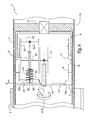
- la figure 1 est une coupe de principe d'un réducteur conforme à l'invention dans une première configuration d'utilisation ;
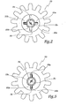
- la figure 2 est une coupe partielle selon la ligne II-II à la figure 1 ;
- la figure 3 est une vue en perspective éclatée d'un satellite du réducteur des figures 1 et 2 ;
- la figure 4 est une vue analogue à la figure 1 lorsque le réducteur est en configuration bloquée ;
- la figure 5 est une coupe selon la ligne V-V à la figure 2 ;
- la figure 6 est une vue analogue à la figure 1, pour un réducteur conforme à un second mode de réalisation de l'invention ;
- la figure 7 est une vue en perspective d'un barillet utilisé dans le mode de réalisation de la figure 6 ; et
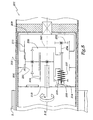
- la figure 8 est une vue analogue à la figure 6, pour un réducteur conforme à un troisième mode de réalisation de l'invention.
- Le réducteur 1 représenté sur les figures comprend un bâti fixe 2 en forme de cloche centré sur un axe géométrique X-X'. Le bâti 2 permet de supporter un arbre 3 d'entrée du mouvement dans le réducteur, le mouvement étant représenté par une flèche de rotation R. L'arbre 3 est solidaire d'un pignon 4 destiné à engrener avec un ou plusieurs satellites, dont un seul est représentés sur les figures avec la référence 5. Le pignon 4 compte quinze dents.
- Le bâti 2 supporte une denture 6 fixe à quarante sept dents et forme une jupe 7 de réception d'une cloche 8 reliée à une bride de sortie 9 du réducteur 1, la bride 9 étant destinée à être rendue solidaire d'un arbre 10 d'enroulement d'un tablier T d'une installation de fermeture.
- La cloche 8 porte une denture 11 à cinquante dents.
- Le bâti 2 porte une nervure périphérique interne 12 formant butée de positionnement de la cloche 8 dans la jupe 7.
- Le satellite 5 comprend un premier pignon 51 à treize dents en prise à la fois avec le pignon 4 et les dentures 6 et 11.
- Le satellite 5 comprend également un second pignon 52 et un troisième pignon 53 alignés avec le pignon 51 autour d'un axe géométrique X5. Le pignon 53 est solidaire en rotation et en translation d'une première extrémité 54a d'un arbre 54 dont la seconde extrémité 54b est pourvue d'un perçage diamétral 54c de réception d'une goupille 55.
- Lorsque la goupille 55 est montée dans l'orifice 54c, ses deux extrémités 55a et 55b s'étendent selon une direction radiale par rapport à l'axe longitudinal X54 de l'arbre 54 qui, en configuration montée du réducteur, est confondu avec l'axe X5. Les extrémités 55a et 55b font saillie radialement par rapport à l'arbre 54.
- En configuration de fonctionnement du réducteur 1, l'arbre 54 traverse les pignons 51 et 53, de sorte que son extrémité 54b et la goupille 55 sont disposées entre le pignon 53 et une cloison d'extrémité 13 du bâti 2 et qu'il est entraîné en rotation par le pignon 51 autour de l'axe X-X' lorsque le pignon 4 tourne.
- Pour pouvoir être traversé par l'extrémité 54b de l'arbre 54, le pignon 53 est pourvu de deux encoches 56 diamétralement opposées et dont les dimensions sont suffisantes pour laisser passer les extrémités 55a et 55b.
- Le premier pignon 51 est monté libre en rotation sur l'arbre 54 mais tenu axialement par rapport à celui-ci par tout moyen approprié, par exemple grâce à un ou des circlips.
- Une collerette annulaire 15 fait saillie par rapport à la denture 11 et est destinée à être insérée entre les pignons 51 et 52, ce qui permet de caler axialement le satellite 5 par rapport aux éléments 2 et 9.
- Un ressort 57 est intercalé autour de l'axe 54 entre les pignons 51 et 53, ce ressort étant comprimé, de telle sorte qu'il exerce sur le pignon 53 un effort E ayant tendance à pousser le pignon 53 en direction de la cloison 13 puisque le satellite 5 est calé axialement.
- On note 53c le moyeu du troisième pignon 53.
- La cloison 13 porte, sur sa face interne 13a orientée vers le satellite 5 des butées 14 réparties circulairement autour de l'axe X-X' et faisant saillie par rapport à la cloison 14.
- Lors de l'assemblage du satellite 5, l'extrémité 54b de l'arbre 54 équipée de la goupille 55 est introduite à travers une ouverture centrale 53d du troisième pignon, les extrémités 55a et 55b de la goupille 55 passant à travers les encoches 56. Ensuite, un mouvement de rotation d'environ 90° est imprimé à l'arbre 54 alors que le pignon 53 maintenu en position, de telle sorte que la goupille 55 est orientée sensiblement à 90° par rapport aux encoches 56. On est alors dans la configuration des figures 1 et 2. La goupille 55 constitue ainsi une butée d'arrêt à un mouvement du pignon 53, sous l'effort E, et permet de maintenir le moyeu 53c à distance des butées 14.
- Au cours du fonctionnement normal du réducteur, celui-ci est dans la configuration des figures 1 et 2 et, si un mouvement de rotation R est imprimé à l'arbre 3, celui-ci est transmis par les pignons 4 et 51 à la denture 11 alors que la denture 6 constitue un point fixe, ce qui permet une mise en mouvement de la cloche 8 et de la bride 9 dans un sens ou dans l'autre autour de l'axe X-X'. L'arbre 10 est ainsi entraîné en rotation R' autour de l'axe X-X' pour l'enroulement ou le déroulement du tablier T.
- Les trois pignons 51, 52 et 53 ayant le même nombre de dents, treize dans l'exemple représenté, ils ont tous la même vitesse angulaire, de sorte que l'orientation angulaire des pignons 52 et 53 et des éléments 55 et 56 l'un par rapport à l'autre demeure et que la goupille 55 conserve sa fonction de moyen d'arrêt du pignon 53 à l'encontre de l'effort E et que le moyeu 53c demeure éloigné de la cloison 13.
- Si une rupture intervient entre le pignon 51 et l'une des dentures 6 ou 11, le synchronisme du mouvement des pignons 52 et 53 est interrompu et, du fait de la différence de vitesse angulaire de ces pignons, les encoches 56 sont amenées en regard des extrémités 55a et 55b. Dans ce cas, le pignon 53 est poussé par l'effort E dû au ressort 57 en direction de la cloison 13 et, sous l'effet de la rotation en cours, le moyeu 53c vient s'immobiliser contre l'une des butées 14.
- Le satellite 5 dans son ensemble est alors bloqué en rotation autour de l'axe X-X'. En particulier, l'arbre 54 est bloqué en rotation autour de cet axe, de sorte que les premier et second satellites sont bloqués, de même que la denture 11, la cloche 8 et la bride 9. Ainsi, l'arbre 10 est bloqué en rotation autour de l'axe X-X' et le tablier T ne risque pas de descendre sous l'effet de son propre poids.
- L'invention permet donc d'assurer un blocage de l'arbre d'enroulement 10 pour toute défaillance de la liaison cinématique entre les pignons 4 et 53 ou entre les pignons 52 et 53. En particulier, l'invention permet de réagir à une rupture de l'engrènement entre le premier pignon 51 et l'une des dentures 6 ou 11, ce qui est particulièrement adapté car c'est dans cette zone que le réducteur 1 est le plus sollicité.
- Cependant, le système permet également de réagir à une rupture d'un autre composant de l'installation disposé en amont du réducteur 1. Pour cela, il suffit que le rapport de réduction défini entre le pignon 51 et les dentures 6 et 11 soit irréversible, ce qui est le cas dans l'exemple représenté.
- Dans le second mode de réalisation de l'invention représenté aux figures 6 et 7, les éléments analogues à ceux du premier mode de réalisation portent des références identiques augmentées de 100. Le réducteur 101 de ce mode de réalisation comprend un bâti fixe 102 centré sur un axe X-X' sur lequel est également centré un pignon d'entrée 104 destiné à engrener avec un satellite 105 qui comprend un premier pignon 151 monté sur un arbre 151' intégré dans un barillet 160, plus particulièrement visible à la figure 7. Ce barillet définit un logement L1 de réception du pignon 151.
- Le pignon 151 engrène avec une denture 106 solidaire du bâti 102 et avec une denture 111 ayant un nombre de dents différent et solidaire d'une bride 109 constituant l'organe de sortie du réducteur 101.
- Le barillet 160 définit également un logement L2 de réception d'un second pignon 152 et un logement L3 de réception d'un troisième pignon 153 appartenant au satellite 105.
- Le barillet 160 intègre un arbre 154 globalement parallèle à l'arbre 103 du pignon d'entrée 104 qui est parallèle à l'axe X-X' et à l'arbre 151'. L'arbre 154, qui est représenté par son axe géométrique X154 à la figure 7, débouche dans les logements L2 et L3.
- L'axe géométrique X151 du pignon 151 est également représenté à la figure 7.
- Le barillet 160 définit un volume V intérieur dans lequel est reçu le pignon 104 en configuration montée du réducteur 101.
- Le second pignon 152 engrène avec la denture 111 alors que le troisième pignon 153 engrène avec la denture 106, ces pignons ayant des nombres de dents identiques.
- Le second pignon 152 est solidaire en translation et en rotation avec l'arbre 154 alors que le troisième pignon 153 est chargé par un effort E exercé par un ressort 157 en direction d'un élément d'arrêt 155 formé par une goupille, du type de la goupille 55 du premier mode de réalisation, cet élément étant solidaire de l'arbre 154.
- Le ressort 157 est intercalé entre le pignon 153 et une surface 161 du barillet 160 délimitant le fond du logement L3.
- Comme précédemment, une ou plusieurs butées 114 sont formées sur la face interne d'une cloison 113 du bâti 102.
- En cas de rupture de l'un des composants du réducteur, le fonctionnement est analogue à celui du réducteur du premier mode de réalisation. En résumé, le troisième pignon 153 se décale angulairement par rapport à la goupille 155 et échappe à celle-ci. Il vient alors se bloquer contre l'une des butées 114, sous l'effet de l'effort E.
- Dans le troisième mode de réalisation de l'invention représenté à la figure 8, les éléments analogues à ceux du premier mode de réalisation portent des référence identiques augmentées de 200. Le réducteur 201 de ce mode de réalisation comprend un bâti 202 centré sur un axe X-X'. Ce bâti 202 porte, sur sa cloison d'extrémité 213, des butées 214.
- Le pignon d'entrée 204 du réducteur engrène avec un satellite 205 qui comprend un premier pignon 251 en prise respectivement avec une denture 206 solidaire du bâti 202 et une denture 211 solidaire d'une bride 209 de sortie du réducteur.
- Un barillet 260 permet de soutenir un arbre 254 sur lequel sont montés un second pignon 252 et un troisième pignon 253 à la façon décrite pour le second mode de réalisation.
- Le troisième pignon est soumis à un effort E exercé par un ressort 257, cet effort ayant tendance à le plaquer contre une goupille d'arrêt 255.
- Ce mode de réalisation diffère du précédent en ce que le troisième pignon 253 engrène non pas avec la denture 206 solidaire du bâti 202 mais avec le pignon d'entrée 204, le second pignon 252 engrenant avec la denture 211, comme le second pignon 152 du second mode de réalisation engrène avec la denture 111.
- Comme précédemment, en cas de rupture de l'un des composants du réducteur 201, le décalage angulaire du troisième pignon 253 par rapport à l'arbre 254 lui permet d'échapper à la goupille 255 et venir se bloquer contre l'une des butées 214.
- Dans les second et troisième modes de réalisation, le blocage du troisième pignon 153 ou 253 bloque le barillet 160 ou 260 dans sa rotation autour de l'axe X-X' du réducteur, ce qui a pour effet de bloquer la denture de sortie 111 ou 211 et la bride 109 ou 209 correspondante.
- Dans les second et troisième modes de réalisation, la géométrie et le positionnement du barillet 160 ou 260 sont tels que l'arbre 154 ou 254 est entraîné en rotation autour de l'axe X-X' lorsque le pignon d'entrée 104 ou 204 tourne.
- L'invention a été représentée avec un réducteur comprenant un unique satellite. Bien entendu elle est applicable avec un réducteur comprenant deux ou plus de deux satellites.
- L'invention a été représentée avec un réducteur sans porte-satellites. Elle est bien entendu applicable avec un réducteur muni d'un porte-satellites.
- L'invention a été représentée avec un satellite dont les premier, second et troisième pignons ont un même nombre de dents. Ceci n'est cependant pas obligatoire. En particulier, les second et troisième pignons 52, 53 ou analogues peuvent avoir des nombres de dents différents, pour autant que le nombre de dents des dentures 6 et 11 ou analogues est adapté.
- En pratique, les vitesse angulaires des second et troisième pignons n'ont pas à être rigoureusement identiques dans la mesure ou une différence peu importante de ces vitesses peut résulter dans un décalage angulaire faible du pignon 53 par rapport à l'arbre 54. Ainsi, pour autant que ce faible décalage n'amène pas la goupille 55 dans la position de la figure 5 sur une course correspondant à l'enroulement ou au déroulement complet du tablier, le réducteur fonctionne correctement. De même en est-il en ce qui concerne les second et troisième modes de réalisation.
- Bien qu'il s'agisse d'une application particulièrement avantageuse, l'invention n'est pas limitée au domaine des mécanismes de fermeture ou de protection solaire. Elle peut être mise en oeuvre dans tout domaine où une sécurisation d'un réducteur épicycloïdal est recherchée.
Claims (13)
- Réducteur épicycloidal (1) incluant au moins un satellite (5;105;205) susceptible d'un mouvement de rotation autour d'un axe principal dudit réducteurs (1) et comprenant un premier pignon (51;151;251) en prise avec deux dentures (6,11;106,111) pourvues de dents en nombres différents, caractérisé en ce que ledit satellite (5 ; 105 ; 205) comprend un second pignon (52 ; 152 ; 252) et un troisième pignon (53 ; 153 ; 253) respectivement en prise chacun avec une desdites dentures (6, 11 ; 106, 111) ou avec l'une desdites dentures (211) et avec un pignon d'entrée (204) du réducteur (1 ; 101 ; 201), ledit second pignon étant solidaire en rotation et en translation d'un arbre (54 ; 154 ; 254) apte à être entraîné en rotation par ledit premier pignon (51 ; 151 ; 251) autour dudit axe principal (X-X') alors que ledit troisième pignon est monté sur ledit arbre avec possibilité de rotation, en étant chargé (E) contre un élément d'arrêt (55 ; 155 ; 255) solidaire en rotation et en translation avec ledit arbre, ledit troisième pignon étant apte à échapper audit élément, par un mouvement de rotation autour dudit arbre, et à venir en prise contre une butée (14 ; 114 ; 214) de blocage de la rotation dudit satellite autour dudit axe (X-X'), lesdits second et troisième pignons ayant, en fonctionnement normal dudit réducteur, sensiblement la même vitesse angulaire de rotation.
- Réducteur selon la revendication 1, caractérisé en ce que ledit arbre (54) traverse ledit premier pignon (51), avec possibilité de rotation.
- Réducteur selon la revendication 1, caractérisé en ce que ledit arbre (154 ; 254) est intégré dans un barillet (160 ; 260) formant des logements de réception des premier, second et troisième pignons (151-153 ; 251-253).
- Réducteur selon l'une des revendications précédentes, caractérisé en ce qu'il comprend des moyens (57 ; 157 ; 257) de charge élastique (E) dudit troisième pignon (53 ; 153 ; 253) en direction dudit élément d'arrêt (55 ; 155 ; 255) et/ou de ladite butée (14 ; 114 ; 214).
- Réducteur selon les revendications 2 ou 3 et 4, caractérisé en ce que lesdits moyens de charge comprennent un ressort de compression (57) intercalé, autour dudit arbre (54), entre lesdits premier (51) et troisième (53) pignons ou entre ledit barillet (160 ; 260) et ledit troisième pignon (153 ; 253).
- Réducteur selon l'une des revendications précédentes, caractérisé en ce que ledit élément d'arrêt forme au moins une saillie (55a, 55b) selon une direction essentiellement radiale par rapport audit arbre (54), ledit troisième pignon (53 ; 153 ; 253) étant pourvu d'au moins une encoche (56) de passage de ladite saillie, dans certaines orientations angulaires dudit troisième pignon par rapport audit arbre.
- Réducteur selon l'une des revendications précédentes, caractérisé en ce que ladite butée (14 ; 114 ; 214) est formée sur une face interne (13a) d'une cloison (13 ; 113 ; 213) d'un bâti fixe (2 ; 102 ; 202) dudit réducteur (1 ; 101 ; 201).
- Réducteur selon la revendication 5, caractérisé en ce que ledit bâti (2 ; 102 ; 202) porte plusieurs butées (14 ; 114 ; 214) réparties circulairement autour d'un axe central (X-X') dudit réducteur.
- Réducteur selon l'une des revendications précédentes, caractérisé en ce que lesdits premier, second et troisième pignons (51-53 ; 151-153) ont un même nombre de dents, lesdits premier et second pignons engrenant ensemble sur la première (11 ; 111) desdites deux dentures alors que lesdits premier et troisième pignons engrènent ensemble sur la seconde (6 ; 106) desdites deux dentures.
- Réducteur selon l'une des revendications précédente, caractérisé en ce que l'une au moins desdites dentures (6, 11 ; 106, 111 ; 206, 211) en prise avec ledit premier pignon porte un élément (15) de maintien axial dudit satellite (5 ; 105 ; 205).
- Réducteur selon l'une des revendications précédentes, caractérisé en ce qu'il comprend un arbre d'entrée (3 ; 103) solidaire d'un pignon central (4 ; 104 ; 204) en prise avec ledit premier pignon (51 ; 151 ; 251), l'organe de sortie (9 ; 109 ; 209) dudit réducteur (1 ; 101 ; 201) étant solidaire de l'une desdites deux dentures (6, 11 ; 106, 111 ; 106, 211).
- Réducteur selon l'une des revendications précédentes, caractérisé en ce qu'il est irréversible.
- Mécanisme de manoeuvre d'une installation de fermeture ou de protection solaire comprenant un organe d'entraînement, mécanique ou électrique, d'un arbre d'enroulement (10) d'un tablier (T) et au moins un réducteur (1 ; 101 ; 201) selon l'une des revendications précédentes monté entre un arbre de sortie dudit organe d'entraînement et ledit arbre d'enroulement.
Applications Claiming Priority (2)
| Application Number | Priority Date | Filing Date | Title |
|---|---|---|---|
| FR0106026 | 2001-05-04 | ||
| FR0106026A FR2824375B1 (fr) | 2001-05-04 | 2001-05-04 | Reducteur epicycloidal et mecanisme de manoeuvre d'une installation de fermeture de protection solaire comprenant un tel reducteur |
Publications (3)
| Publication Number | Publication Date |
|---|---|
| EP1255060A2 EP1255060A2 (fr) | 2002-11-06 |
| EP1255060A3 EP1255060A3 (fr) | 2005-12-14 |
| EP1255060B1 true EP1255060B1 (fr) | 2006-11-29 |
Family
ID=8863011
Family Applications (1)
| Application Number | Title | Priority Date | Filing Date |
|---|---|---|---|
| EP02356084A Expired - Lifetime EP1255060B1 (fr) | 2001-05-04 | 2002-05-03 | Reducteur epicycloidal et mecanisme de manoeuvre d'une installation de fermeture de protection solaire comprenant un tel reducteur |
Country Status (5)
| Country | Link |
|---|---|
| EP (1) | EP1255060B1 (fr) |
| AT (1) | ATE347015T1 (fr) |
| DE (1) | DE60216355T2 (fr) |
| ES (1) | ES2251889T1 (fr) |
| FR (1) | FR2824375B1 (fr) |
Family Cites Families (8)
| Publication number | Priority date | Publication date | Assignee | Title |
|---|---|---|---|---|
| DE2417623B1 (de) * | 1974-04-10 | 1975-09-04 | Elpatag Ag, Zug (Schweiz) | Sicherung einer Welle gegen Drehen bei unterbrochener Antriebsverbindung |
| FR2468986A1 (fr) * | 1979-06-20 | 1981-05-08 | Marche Roche Ets | Perfectionnements aux systemes d'arret automatique de fin de course pour dispositifs a commande electrique |
| FR2480846A1 (fr) * | 1980-04-18 | 1981-10-23 | Carpano & Pons | Dispositif d'entrainement, pour stores a rouleau, volets roulants, ou similaires |
| DE3623612A1 (de) * | 1986-07-12 | 1988-01-28 | Hueppe Gmbh | Getriebe fuer eine gelenkarmmarkise |
| DE3701106C1 (fr) | 1987-01-16 | 1988-06-23 | W. U. H. Neukirchen Gmbh & Co Kg, 4060 Viersen, De | |
| DE4324866A1 (de) | 1993-07-23 | 1995-01-26 | Tornado Antriebstech Gmbh | Fangeinrichtung für Antriebe von Rolltoren |
| FR2744141B1 (fr) | 1996-01-30 | 1998-03-20 | Atochem Elf Sa | Procede pour le traitement oleophobe et hydrophobe du papier ou du carton |
| DE19934623A1 (de) * | 1999-07-23 | 2001-02-01 | Elero Gmbh | Antriebsvorrichtung aus einem Motor und einem Getriebe |
-
2001
- 2001-05-04 FR FR0106026A patent/FR2824375B1/fr not_active Expired - Fee Related
-
2002
- 2002-05-03 ES ES02356084T patent/ES2251889T1/es active Pending
- 2002-05-03 AT AT02356084T patent/ATE347015T1/de not_active IP Right Cessation
- 2002-05-03 EP EP02356084A patent/EP1255060B1/fr not_active Expired - Lifetime
- 2002-05-03 DE DE60216355T patent/DE60216355T2/de not_active Expired - Lifetime
Also Published As
| Publication number | Publication date |
|---|---|
| ES2251889T1 (es) | 2006-05-16 |
| FR2824375A1 (fr) | 2002-11-08 |
| DE60216355T2 (de) | 2007-09-13 |
| DE60216355D1 (de) | 2007-01-11 |
| FR2824375B1 (fr) | 2003-06-13 |
| EP1255060A3 (fr) | 2005-12-14 |
| ATE347015T1 (de) | 2006-12-15 |
| EP1255060A2 (fr) | 2002-11-06 |
Similar Documents
| Publication | Publication Date | Title |
|---|---|---|
| EP0790385A1 (fr) | Dispositif de manoeuvre pour volet roulant | |
| CH642714A5 (fr) | Dispositif d'entrainement, pour stores a rouleau ou volets roulants. | |
| FR2736125A1 (fr) | Differentiel de verrouillage incluant des elements de retenue d'arbre | |
| FR2563203A1 (fr) | Treuil | |
| FR2819467A1 (fr) | Actionnement de blocage de stationnement pour un dispositif de blocage de stationnement d'un vehicule automobile | |
| FR2615150A1 (fr) | Enrouleur de ceinture de securite avec dispositif de tension | |
| FR2869938A1 (fr) | Systeme de porte pour vehicule de transport utilisant un agencement de blocage a compression | |
| WO2022106681A1 (fr) | Dispositif d'entraînement électrique d'un essieu d'un vehicule | |
| EP1509705B1 (fr) | Actionneur a deux moteurs, un reducteur differentiel et un limiteur de couple | |
| EP2783062A2 (fr) | Actionneur électrique tubulaire d'entraînement pour un écran domotique, procédé d'assemblage d'un tel actionneur et installation comprenant un tel actionneur | |
| EP0188164B1 (fr) | Bloc de direction de véhicule automobile, comportant un coussin central fixe | |
| EP1488070B1 (fr) | Dispositif de securite et mecanisme de manoeuvre d'une installation de fermeture ou de protection solaire incorporant un tel dispositif | |
| EP0614778B1 (fr) | Différentiel de transmission pour boîte de vitesses étanche | |
| EP0229681B1 (fr) | Dispositif d'entraînement en rotation du tube d'enroulage d'un store à rouleau, volet roulant ou similaire | |
| EP0153887B1 (fr) | Dispositif et outillage de correction de balourd d'un rotor de turbomachine et procédé pour la mise en oeuvre | |
| EP0236650A1 (fr) | Dispositif d'entraînement de deux arbres alignés, avec mécanisme différentiel, notamment deux arbres de transmission reliés à deux roues arrière de véhicule | |
| EP3333637A1 (fr) | Mouvement d'horlogerie mecanique a detection de reserve de marche | |
| EP1255060A2 (fr) | Reducteur epicycloidal et mecanisme de manoeuvre d'une installation de fermeture de protection solaire comprenant un tel reducteur | |
| EP3306416A1 (fr) | Mouvement d'horlogerie mecanique a detection de reserve de marche | |
| EP0775798B1 (fr) | Dispositif d'entraínement en rotation d'un élément d'enroulement de volet roulant | |
| EP4187126B1 (fr) | Système réducteur à engrenages et bagues dentées pour un moteur d'un ensemble occultant où le système réducteur présente un bruit de fonctionnement réduit | |
| FR2640015A1 (fr) | Differentiel mecanique | |
| EP0451895B1 (fr) | Dispositif d'entraînement d'un rouleau sur une machine à tisser | |
| EP1783394B1 (fr) | Dispositif de sécurité de transmission mécanique par engrenage irréversible a l'arrêt | |
| WO1998048399A1 (fr) | Dispositif d'affichage |
Legal Events
| Date | Code | Title | Description |
|---|---|---|---|
| PUAI | Public reference made under article 153(3) epc to a published international application that has entered the european phase |
Free format text: ORIGINAL CODE: 0009012 |
|
| AK | Designated contracting states |
Kind code of ref document: A2 Designated state(s): AT BE CH CY DE DK ES FI FR GB GR IE IT LI LU MC NL PT SE TR |
|
| AX | Request for extension of the european patent |
Free format text: AL;LT;LV;MK;RO;SI |
|
| PUAL | Search report despatched |
Free format text: ORIGINAL CODE: 0009013 |
|
| AK | Designated contracting states |
Kind code of ref document: A3 Designated state(s): AT BE CH CY DE DK ES FI FR GB GR IE IT LI LU MC NL PT SE TR |
|
| AX | Request for extension of the european patent |
Extension state: AL LT LV MK RO SI |
|
| RIC1 | Information provided on ipc code assigned before grant |
Ipc: 7F 16H 1/46 B Ipc: 7E 06B 9/84 A |
|
| 17P | Request for examination filed |
Effective date: 20060223 |
|
| GRAP | Despatch of communication of intention to grant a patent |
Free format text: ORIGINAL CODE: EPIDOSNIGR1 |
|
| AKX | Designation fees paid |
Designated state(s): AT BE CH CY DE DK ES FI FR GB GR IE IT LI LU MC NL PT SE TR |
|
| GRAS | Grant fee paid |
Free format text: ORIGINAL CODE: EPIDOSNIGR3 |
|
| GRAA | (expected) grant |
Free format text: ORIGINAL CODE: 0009210 |
|
| AK | Designated contracting states |
Kind code of ref document: B1 Designated state(s): AT BE CH CY DE DK ES FI FR GB GR IE IT LI LU MC NL PT SE TR |
|
| PG25 | Lapsed in a contracting state [announced via postgrant information from national office to epo] |
Ref country code: IT Free format text: LAPSE BECAUSE OF FAILURE TO SUBMIT A TRANSLATION OF THE DESCRIPTION OR TO PAY THE FEE WITHIN THE PRESCRIBED TIME-LIMIT;WARNING: LAPSES OF ITALIAN PATENTS WITH EFFECTIVE DATE BEFORE 2007 MAY HAVE OCCURRED AT ANY TIME BEFORE 2007. THE CORRECT EFFECTIVE DATE MAY BE DIFFERENT FROM THE ONE RECORDED. Effective date: 20061129 Ref country code: FI Free format text: LAPSE BECAUSE OF FAILURE TO SUBMIT A TRANSLATION OF THE DESCRIPTION OR TO PAY THE FEE WITHIN THE PRESCRIBED TIME-LIMIT Effective date: 20061129 Ref country code: AT Free format text: LAPSE BECAUSE OF FAILURE TO SUBMIT A TRANSLATION OF THE DESCRIPTION OR TO PAY THE FEE WITHIN THE PRESCRIBED TIME-LIMIT Effective date: 20061129 Ref country code: IE Free format text: LAPSE BECAUSE OF FAILURE TO SUBMIT A TRANSLATION OF THE DESCRIPTION OR TO PAY THE FEE WITHIN THE PRESCRIBED TIME-LIMIT Effective date: 20061129 |
|
| REG | Reference to a national code |
Ref country code: GB Ref legal event code: FG4D Free format text: NOT ENGLISH |
|
| REG | Reference to a national code |
Ref country code: CH Ref legal event code: EP |
|
| GBT | Gb: translation of ep patent filed (gb section 77(6)(a)/1977) |
Effective date: 20061220 |
|
| REG | Reference to a national code |
Ref country code: IE Ref legal event code: FG4D Free format text: LANGUAGE OF EP DOCUMENT: FRENCH |
|
| REF | Corresponds to: |
Ref document number: 60216355 Country of ref document: DE Date of ref document: 20070111 Kind code of ref document: P |
|
| PG25 | Lapsed in a contracting state [announced via postgrant information from national office to epo] |
Ref country code: DK Free format text: LAPSE BECAUSE OF FAILURE TO SUBMIT A TRANSLATION OF THE DESCRIPTION OR TO PAY THE FEE WITHIN THE PRESCRIBED TIME-LIMIT Effective date: 20070228 Ref country code: SE Free format text: LAPSE BECAUSE OF FAILURE TO SUBMIT A TRANSLATION OF THE DESCRIPTION OR TO PAY THE FEE WITHIN THE PRESCRIBED TIME-LIMIT Effective date: 20070228 |
|
| PG25 | Lapsed in a contracting state [announced via postgrant information from national office to epo] |
Ref country code: ES Free format text: LAPSE BECAUSE OF FAILURE TO SUBMIT A TRANSLATION OF THE DESCRIPTION OR TO PAY THE FEE WITHIN THE PRESCRIBED TIME-LIMIT Effective date: 20070312 |
|
| PG25 | Lapsed in a contracting state [announced via postgrant information from national office to epo] |
Ref country code: PT Free format text: LAPSE BECAUSE OF FAILURE TO SUBMIT A TRANSLATION OF THE DESCRIPTION OR TO PAY THE FEE WITHIN THE PRESCRIBED TIME-LIMIT Effective date: 20070430 |
|
| REG | Reference to a national code |
Ref country code: IE Ref legal event code: FD4D |
|
| PLBE | No opposition filed within time limit |
Free format text: ORIGINAL CODE: 0009261 |
|
| STAA | Information on the status of an ep patent application or granted ep patent |
Free format text: STATUS: NO OPPOSITION FILED WITHIN TIME LIMIT |
|
| 26N | No opposition filed |
Effective date: 20070830 |
|
| REG | Reference to a national code |
Ref country code: CH Ref legal event code: PL |
|
| PG25 | Lapsed in a contracting state [announced via postgrant information from national office to epo] |
Ref country code: MC Free format text: LAPSE BECAUSE OF NON-PAYMENT OF DUE FEES Effective date: 20070531 |
|
| PG25 | Lapsed in a contracting state [announced via postgrant information from national office to epo] |
Ref country code: LI Free format text: LAPSE BECAUSE OF NON-PAYMENT OF DUE FEES Effective date: 20070531 Ref country code: CH Free format text: LAPSE BECAUSE OF NON-PAYMENT OF DUE FEES Effective date: 20070531 |
|
| PG25 | Lapsed in a contracting state [announced via postgrant information from national office to epo] |
Ref country code: GR Free format text: LAPSE BECAUSE OF FAILURE TO SUBMIT A TRANSLATION OF THE DESCRIPTION OR TO PAY THE FEE WITHIN THE PRESCRIBED TIME-LIMIT Effective date: 20070301 |
|
| PG25 | Lapsed in a contracting state [announced via postgrant information from national office to epo] |
Ref country code: LU Free format text: LAPSE BECAUSE OF NON-PAYMENT OF DUE FEES Effective date: 20070503 Ref country code: CY Free format text: LAPSE BECAUSE OF FAILURE TO SUBMIT A TRANSLATION OF THE DESCRIPTION OR TO PAY THE FEE WITHIN THE PRESCRIBED TIME-LIMIT Effective date: 20061129 |
|
| PG25 | Lapsed in a contracting state [announced via postgrant information from national office to epo] |
Ref country code: TR Free format text: LAPSE BECAUSE OF FAILURE TO SUBMIT A TRANSLATION OF THE DESCRIPTION OR TO PAY THE FEE WITHIN THE PRESCRIBED TIME-LIMIT Effective date: 20061129 |
|
| REG | Reference to a national code |
Ref country code: FR Ref legal event code: PLFP Year of fee payment: 15 |
|
| REG | Reference to a national code |
Ref country code: FR Ref legal event code: PLFP Year of fee payment: 16 |
|
| PGFP | Annual fee paid to national office [announced via postgrant information from national office to epo] |
Ref country code: GB Payment date: 20170517 Year of fee payment: 16 |
|
| PGFP | Annual fee paid to national office [announced via postgrant information from national office to epo] |
Ref country code: BE Payment date: 20170531 Year of fee payment: 16 |
|
| REG | Reference to a national code |
Ref country code: FR Ref legal event code: PLFP Year of fee payment: 17 |
|
| GBPC | Gb: european patent ceased through non-payment of renewal fee |
Effective date: 20180503 |
|
| REG | Reference to a national code |
Ref country code: BE Ref legal event code: MM Effective date: 20180531 |
|
| PG25 | Lapsed in a contracting state [announced via postgrant information from national office to epo] |
Ref country code: GB Free format text: LAPSE BECAUSE OF NON-PAYMENT OF DUE FEES Effective date: 20180503 |
|
| PG25 | Lapsed in a contracting state [announced via postgrant information from national office to epo] |
Ref country code: BE Free format text: LAPSE BECAUSE OF NON-PAYMENT OF DUE FEES Effective date: 20180531 |
|
| PGFP | Annual fee paid to national office [announced via postgrant information from national office to epo] |
Ref country code: FR Payment date: 20210414 Year of fee payment: 20 Ref country code: DE Payment date: 20210507 Year of fee payment: 20 Ref country code: NL Payment date: 20210415 Year of fee payment: 20 |
|
| REG | Reference to a national code |
Ref country code: DE Ref legal event code: R071 Ref document number: 60216355 Country of ref document: DE |
|
| REG | Reference to a national code |
Ref country code: NL Ref legal event code: MK Effective date: 20220502 |