EP1253591A2 - Leader tape and tape cartridge - Google Patents
Leader tape and tape cartridge Download PDFInfo
- Publication number
- EP1253591A2 EP1253591A2 EP02009237A EP02009237A EP1253591A2 EP 1253591 A2 EP1253591 A2 EP 1253591A2 EP 02009237 A EP02009237 A EP 02009237A EP 02009237 A EP02009237 A EP 02009237A EP 1253591 A2 EP1253591 A2 EP 1253591A2
- Authority
- EP
- European Patent Office
- Prior art keywords
- tape
- welded
- folded
- leader
- leader tape
- Prior art date
- Legal status (The legal status is an assumption and is not a legal conclusion. Google has not performed a legal analysis and makes no representation as to the accuracy of the status listed.)
- Withdrawn
Links
Images





Classifications
-
- B—PERFORMING OPERATIONS; TRANSPORTING
- B29—WORKING OF PLASTICS; WORKING OF SUBSTANCES IN A PLASTIC STATE IN GENERAL
- B29C—SHAPING OR JOINING OF PLASTICS; SHAPING OF MATERIAL IN A PLASTIC STATE, NOT OTHERWISE PROVIDED FOR; AFTER-TREATMENT OF THE SHAPED PRODUCTS, e.g. REPAIRING
- B29C66/00—General aspects of processes or apparatus for joining preformed parts
- B29C66/01—General aspects dealing with the joint area or with the area to be joined
- B29C66/05—Particular design of joint configurations
- B29C66/20—Particular design of joint configurations particular design of the joint lines, e.g. of the weld lines
- B29C66/21—Particular design of joint configurations particular design of the joint lines, e.g. of the weld lines said joint lines being formed by a single dot or dash or by several dots or dashes, i.e. spot joining or spot welding
-
- B—PERFORMING OPERATIONS; TRANSPORTING
- B29—WORKING OF PLASTICS; WORKING OF SUBSTANCES IN A PLASTIC STATE IN GENERAL
- B29C—SHAPING OR JOINING OF PLASTICS; SHAPING OF MATERIAL IN A PLASTIC STATE, NOT OTHERWISE PROVIDED FOR; AFTER-TREATMENT OF THE SHAPED PRODUCTS, e.g. REPAIRING
- B29C53/00—Shaping by bending, folding, twisting, straightening or flattening; Apparatus therefor
- B29C53/36—Bending and joining, e.g. for making hollow articles
- B29C53/38—Bending and joining, e.g. for making hollow articles by bending sheets or strips at right angles to the longitudinal axis of the article being formed and joining the edges
- B29C53/40—Bending and joining, e.g. for making hollow articles by bending sheets or strips at right angles to the longitudinal axis of the article being formed and joining the edges for articles of definite length, i.e. discrete articles
- B29C53/42—Bending and joining, e.g. for making hollow articles by bending sheets or strips at right angles to the longitudinal axis of the article being formed and joining the edges for articles of definite length, i.e. discrete articles using internal forming surfaces, e.g. mandrels
-
- B—PERFORMING OPERATIONS; TRANSPORTING
- B29—WORKING OF PLASTICS; WORKING OF SUBSTANCES IN A PLASTIC STATE IN GENERAL
- B29C—SHAPING OR JOINING OF PLASTICS; SHAPING OF MATERIAL IN A PLASTIC STATE, NOT OTHERWISE PROVIDED FOR; AFTER-TREATMENT OF THE SHAPED PRODUCTS, e.g. REPAIRING
- B29C65/00—Joining or sealing of preformed parts, e.g. welding of plastics materials; Apparatus therefor
- B29C65/02—Joining or sealing of preformed parts, e.g. welding of plastics materials; Apparatus therefor by heating, with or without pressure
-
- B—PERFORMING OPERATIONS; TRANSPORTING
- B29—WORKING OF PLASTICS; WORKING OF SUBSTANCES IN A PLASTIC STATE IN GENERAL
- B29C—SHAPING OR JOINING OF PLASTICS; SHAPING OF MATERIAL IN A PLASTIC STATE, NOT OTHERWISE PROVIDED FOR; AFTER-TREATMENT OF THE SHAPED PRODUCTS, e.g. REPAIRING
- B29C65/00—Joining or sealing of preformed parts, e.g. welding of plastics materials; Apparatus therefor
- B29C65/02—Joining or sealing of preformed parts, e.g. welding of plastics materials; Apparatus therefor by heating, with or without pressure
- B29C65/08—Joining or sealing of preformed parts, e.g. welding of plastics materials; Apparatus therefor by heating, with or without pressure using ultrasonic vibrations
-
- B—PERFORMING OPERATIONS; TRANSPORTING
- B29—WORKING OF PLASTICS; WORKING OF SUBSTANCES IN A PLASTIC STATE IN GENERAL
- B29C—SHAPING OR JOINING OF PLASTICS; SHAPING OF MATERIAL IN A PLASTIC STATE, NOT OTHERWISE PROVIDED FOR; AFTER-TREATMENT OF THE SHAPED PRODUCTS, e.g. REPAIRING
- B29C66/00—General aspects of processes or apparatus for joining preformed parts
- B29C66/01—General aspects dealing with the joint area or with the area to be joined
- B29C66/05—Particular design of joint configurations
- B29C66/10—Particular design of joint configurations particular design of the joint cross-sections
- B29C66/11—Joint cross-sections comprising a single joint-segment, i.e. one of the parts to be joined comprising a single joint-segment in the joint cross-section
- B29C66/112—Single lapped joints
- B29C66/1122—Single lap to lap joints, i.e. overlap joints
-
- B—PERFORMING OPERATIONS; TRANSPORTING
- B29—WORKING OF PLASTICS; WORKING OF SUBSTANCES IN A PLASTIC STATE IN GENERAL
- B29C—SHAPING OR JOINING OF PLASTICS; SHAPING OF MATERIAL IN A PLASTIC STATE, NOT OTHERWISE PROVIDED FOR; AFTER-TREATMENT OF THE SHAPED PRODUCTS, e.g. REPAIRING
- B29C66/00—General aspects of processes or apparatus for joining preformed parts
- B29C66/40—General aspects of joining substantially flat articles, e.g. plates, sheets or web-like materials; Making flat seams in tubular or hollow articles; Joining single elements to substantially flat surfaces
- B29C66/41—Joining substantially flat articles ; Making flat seams in tubular or hollow articles
- B29C66/43—Joining a relatively small portion of the surface of said articles
-
- B—PERFORMING OPERATIONS; TRANSPORTING
- B29—WORKING OF PLASTICS; WORKING OF SUBSTANCES IN A PLASTIC STATE IN GENERAL
- B29C—SHAPING OR JOINING OF PLASTICS; SHAPING OF MATERIAL IN A PLASTIC STATE, NOT OTHERWISE PROVIDED FOR; AFTER-TREATMENT OF THE SHAPED PRODUCTS, e.g. REPAIRING
- B29C66/00—General aspects of processes or apparatus for joining preformed parts
- B29C66/40—General aspects of joining substantially flat articles, e.g. plates, sheets or web-like materials; Making flat seams in tubular or hollow articles; Joining single elements to substantially flat surfaces
- B29C66/41—Joining substantially flat articles ; Making flat seams in tubular or hollow articles
- B29C66/43—Joining a relatively small portion of the surface of said articles
- B29C66/431—Joining the articles to themselves
-
- B—PERFORMING OPERATIONS; TRANSPORTING
- B29—WORKING OF PLASTICS; WORKING OF SUBSTANCES IN A PLASTIC STATE IN GENERAL
- B29C—SHAPING OR JOINING OF PLASTICS; SHAPING OF MATERIAL IN A PLASTIC STATE, NOT OTHERWISE PROVIDED FOR; AFTER-TREATMENT OF THE SHAPED PRODUCTS, e.g. REPAIRING
- B29C66/00—General aspects of processes or apparatus for joining preformed parts
- B29C66/50—General aspects of joining tubular articles; General aspects of joining long products, i.e. bars or profiled elements; General aspects of joining single elements to tubular articles, hollow articles or bars; General aspects of joining several hollow-preforms to form hollow or tubular articles
- B29C66/51—Joining tubular articles, profiled elements or bars; Joining single elements to tubular articles, hollow articles or bars; Joining several hollow-preforms to form hollow or tubular articles
- B29C66/54—Joining several hollow-preforms, e.g. half-shells, to form hollow articles, e.g. for making balls, containers; Joining several hollow-preforms, e.g. half-cylinders, to form tubular articles
-
- B—PERFORMING OPERATIONS; TRANSPORTING
- B29—WORKING OF PLASTICS; WORKING OF SUBSTANCES IN A PLASTIC STATE IN GENERAL
- B29C—SHAPING OR JOINING OF PLASTICS; SHAPING OF MATERIAL IN A PLASTIC STATE, NOT OTHERWISE PROVIDED FOR; AFTER-TREATMENT OF THE SHAPED PRODUCTS, e.g. REPAIRING
- B29C66/00—General aspects of processes or apparatus for joining preformed parts
- B29C66/80—General aspects of machine operations or constructions and parts thereof
-
- B—PERFORMING OPERATIONS; TRANSPORTING
- B29—WORKING OF PLASTICS; WORKING OF SUBSTANCES IN A PLASTIC STATE IN GENERAL
- B29C—SHAPING OR JOINING OF PLASTICS; SHAPING OF MATERIAL IN A PLASTIC STATE, NOT OTHERWISE PROVIDED FOR; AFTER-TREATMENT OF THE SHAPED PRODUCTS, e.g. REPAIRING
- B29C66/00—General aspects of processes or apparatus for joining preformed parts
- B29C66/80—General aspects of machine operations or constructions and parts thereof
- B29C66/81—General aspects of the pressing elements, i.e. the elements applying pressure on the parts to be joined in the area to be joined, e.g. the welding jaws or clamps
- B29C66/814—General aspects of the pressing elements, i.e. the elements applying pressure on the parts to be joined in the area to be joined, e.g. the welding jaws or clamps characterised by the design of the pressing elements, e.g. of the welding jaws or clamps
- B29C66/8141—General aspects of the pressing elements, i.e. the elements applying pressure on the parts to be joined in the area to be joined, e.g. the welding jaws or clamps characterised by the design of the pressing elements, e.g. of the welding jaws or clamps characterised by the surface geometry of the part of the pressing elements, e.g. welding jaws or clamps, coming into contact with the parts to be joined
- B29C66/81427—General aspects of the pressing elements, i.e. the elements applying pressure on the parts to be joined in the area to be joined, e.g. the welding jaws or clamps characterised by the design of the pressing elements, e.g. of the welding jaws or clamps characterised by the surface geometry of the part of the pressing elements, e.g. welding jaws or clamps, coming into contact with the parts to be joined comprising a single ridge, e.g. for making a weakening line; comprising a single tooth
-
- G—PHYSICS
- G11—INFORMATION STORAGE
- G11B—INFORMATION STORAGE BASED ON RELATIVE MOVEMENT BETWEEN RECORD CARRIER AND TRANSDUCER
- G11B23/00—Record carriers not specific to the method of recording or reproducing; Accessories, e.g. containers, specially adapted for co-operation with the recording or reproducing apparatus ; Intermediate mediums; Apparatus or processes specially adapted for their manufacture
- G11B23/02—Containers; Storing means both adapted to cooperate with the recording or reproducing means
- G11B23/04—Magazines; Cassettes for webs or filaments
- G11B23/08—Magazines; Cassettes for webs or filaments for housing webs or filaments having two distinct ends
- G11B23/107—Magazines; Cassettes for webs or filaments for housing webs or filaments having two distinct ends using one reel or core, one end of the record carrier coming out of the magazine or cassette
-
- G—PHYSICS
- G11—INFORMATION STORAGE
- G11B—INFORMATION STORAGE BASED ON RELATIVE MOVEMENT BETWEEN RECORD CARRIER AND TRANSDUCER
- G11B23/00—Record carriers not specific to the method of recording or reproducing; Accessories, e.g. containers, specially adapted for co-operation with the recording or reproducing apparatus ; Intermediate mediums; Apparatus or processes specially adapted for their manufacture
- G11B23/20—Record carriers not specific to the method of recording or reproducing; Accessories, e.g. containers, specially adapted for co-operation with the recording or reproducing apparatus ; Intermediate mediums; Apparatus or processes specially adapted for their manufacture with provision for splicing to provide permanent or temporary connections
- G11B23/26—Record carriers not specific to the method of recording or reproducing; Accessories, e.g. containers, specially adapted for co-operation with the recording or reproducing apparatus ; Intermediate mediums; Apparatus or processes specially adapted for their manufacture with provision for splicing to provide permanent or temporary connections of leaders for loading or threading, e.g. to form a temporary connection
-
- B—PERFORMING OPERATIONS; TRANSPORTING
- B29—WORKING OF PLASTICS; WORKING OF SUBSTANCES IN A PLASTIC STATE IN GENERAL
- B29C—SHAPING OR JOINING OF PLASTICS; SHAPING OF MATERIAL IN A PLASTIC STATE, NOT OTHERWISE PROVIDED FOR; AFTER-TREATMENT OF THE SHAPED PRODUCTS, e.g. REPAIRING
- B29C66/00—General aspects of processes or apparatus for joining preformed parts
- B29C66/80—General aspects of machine operations or constructions and parts thereof
- B29C66/83—General aspects of machine operations or constructions and parts thereof characterised by the movement of the joining or pressing tools
- B29C66/832—Reciprocating joining or pressing tools
- B29C66/8322—Joining or pressing tools reciprocating along one axis
-
- B—PERFORMING OPERATIONS; TRANSPORTING
- B29—WORKING OF PLASTICS; WORKING OF SUBSTANCES IN A PLASTIC STATE IN GENERAL
- B29K—INDEXING SCHEME ASSOCIATED WITH SUBCLASSES B29B, B29C OR B29D, RELATING TO MOULDING MATERIALS OR TO MATERIALS FOR MOULDS, REINFORCEMENTS, FILLERS OR PREFORMED PARTS, e.g. INSERTS
- B29K2995/00—Properties of moulding materials, reinforcements, fillers, preformed parts or moulds
- B29K2995/0003—Properties of moulding materials, reinforcements, fillers, preformed parts or moulds having particular electrical or magnetic properties, e.g. piezoelectric
- B29K2995/0008—Magnetic or paramagnetic
-
- B—PERFORMING OPERATIONS; TRANSPORTING
- B29—WORKING OF PLASTICS; WORKING OF SUBSTANCES IN A PLASTIC STATE IN GENERAL
- B29L—INDEXING SCHEME ASSOCIATED WITH SUBCLASS B29C, RELATING TO PARTICULAR ARTICLES
- B29L2007/00—Flat articles, e.g. films or sheets
- B29L2007/007—Narrow strips, e.g. ribbons, tapes, bands
-
- B—PERFORMING OPERATIONS; TRANSPORTING
- B29—WORKING OF PLASTICS; WORKING OF SUBSTANCES IN A PLASTIC STATE IN GENERAL
- B29L—INDEXING SCHEME ASSOCIATED WITH SUBCLASS B29C, RELATING TO PARTICULAR ARTICLES
- B29L2017/00—Carriers for sound or information
- B29L2017/008—Tapes
Definitions
- This invention relates to a leader tape fixedly attached to a leading end of a tape, such as a magnetic tape for data recording and a cleaning tape for head cleaning, for enabling the tape to be pulled out of a cartridge body, and a tape cartridge incorporating the leader tape.
- the tape cartridge 31 is a one reel-type recording medium cartridge, and is comprised of a cartridge body 2 having an upper half 2a, a lower half 2b, and a lid 2c, a single reel 3, and a magnetic tape 4 (see FIG. 13) for data recording wound around the reel 3 and accommodated in the cartridge body 2.
- a leader tape 35 is fixedly attached to the magnetic tape 4, for enabling the tape 4 to be pulled out of the cartridge body 3 by a record/playback device, not shown. As shown in FIGS.
- this leader tape 35 is comprised of a tape body 11 having one end thereof fixedly attached to the magnetic tape 4, a pin 12 attached to the other end of the tape body 11, and engaging hooks 13, 13 fixed to respective opposite ends of the pin 12.
- the tape body 11 has the other end folded such that it surrounds the periphery of the pin 12, and leading end portions 11b of the other end folded are welded to an opposed tape surface of a root portion 11a (see FIG. 13) of the tape body 11 between the one end fixed to the magnetic tape 4 and the folded portion.
- the leading end portions 11b are welded to the root portion 11a by respective horns X11 for ultrasonic welding. More specifically, first, the leading end portions 11b of the tape body 11 are folded such that they surround the periphery of the pin 12, and brought into contact with the root portion 11a. Then, as shown in FIG. 15, the horns X11 each having a prism shape are brought into contact with the respective surfaces of the leading end portions 11b, and ultrasonic waves are delivered from the horns X11 with the leading end portions 11b being urged against the root portion 11a.
- Each horn X11 has knurls formed on a welding surface (abutment surface via which the horn X11 abuts on the corresponding leading end portion 11b) thereof at a pitch of about 0.6 mm. Therefore, the leading end portions 11b and the root portion 11a are brought into firm contact with each other at the top of each knurl, and are progressively melted and mixed, starting with portions in such a firm contact with each. The portions melted to each other (melted portion) progressively spread until adjacent melted portions overlap each other to cause an area of each leading end portion 11b urged by the corresponding horn X11 and an area at the root portion 11a in contact with the urged area (welded area W11 in FIG. 15) to be entirely welded and mixed to each other.
- each leading end portion 11b and the root portion 11a solidify when they cool to normal temperature. This causes each leading end portion 11b and the root portion 11a to be integrated with each other in the respective above-mentioned areas (welded area W11 in FIG. 15), whereby the attachment of the pin 12 to the tape body 11 is completed.
- the horns X11 having a prism shape are used for welding. Therefore, as shown in FIG.
- each welded area W11 where each leading end portion 11b and the root portion 11a are welded to each other and a corresponding non-welded portion V11 where the leading end portion 11b and the root portion 11a become apart from each other are divided by a boundary line L11 in the form of a straight line perpendicular to the direction of the length of the tape body 11.
- the welding surface of the horn X11 has a size which extends beyond an edge E1 of the tape body 11, and hence the leading end portion 11b and the root portion 11a are welded to each other all over the area between the boundary line L11 and the edge E1
- the boundary line L11 dividing between the welded area W11 and the non-welded area V11 is in the form of a straight line perpendicular to the direction of the length of the tape body 11. Therefore, when the pin 12 is pulled via the hooks 13, 13 in a direction indicated by an arrow C1 in FIG. 15 to pull out the magnetic tape 4, stress is concentrated on a portion of the tape body 11 which is very short with respect to the direction of the length of the tape (portion of the boundary line L11). This can cause breakage of the leading end portion 11b along the boundary line L11 or in the vicinity thereof, as shown in FIG. 16.
- the leading end portion 11b and the root portion 11a are welded to each other all over the area between the boundary line L11 (not shown in this figure) and the edge E1 to cause the leading end portion 11b and the root portion 11a to be substantially completely integrated with each other in the welded area W11, through solidifying, after being melted to each other, so that the thickness of the tape body 11 (root portion 11a) undergoes a sudden change at the edge E1. Therefore, when the pin 12 is pulled in the direction of an arrow C2 in FIG. 15, stress is also concentrated on the portion of this edge E1. This may cause breakage of the root portion 11a at the edge E1 or in the vicinity thereof, as shown in FIG. 17B.
- the horns X11 each having a pin 12 side corner thereof scarcely chamfered e.g. horns X11 each having the corner whose cross-sectional shape is in the form of arc having a radius of 0.1 mm or smaller
- stress is concentrated on a portion along the boundary line L11.
- the residual stress itself of the portion along the boundary line L11 becomes large. This can also cause breakage of the leading portion 11b at the boundary line L11 or in its vicinity, as shown in FIG. 16, when the pulling-out of the magnetic tape 4 is repeatedly carried out.
- each horns X11 having the corner thereof scarcely chamfered forms a juncture of the leading end portion 11b between the welded area W11 and the non-welded area V11, in a manner corresponding to the corner of horn X11. Therefore, when the pin 12 is pulled in the direction indicated by the arrow C2 in FIG. 15 to forcibly expand a juncture angle ⁇ formed between the welded area W11 and the non-welded area V11, stress is concentrated at the very narrow boundary line L11, causing breakage at the portion along the boundary line L11.
- a leader tape including a leader tape body having one end fixed to a tape, for enabling the tape to be pulled out of a cartridge body, and a pin member attached to the leader tape body, for pulling out the tape therewith, the leader tape body having a portion thereof on a side of another end opposite to the one end, the portion being folded such that the folded portion surrounds a periphery of the pin member and that the folded portion has a leading end portion thereof welded to a tape surface of the leader tape body opposed to the folded portion, wherein welding is effected non-densely in at least one of a pin member-side boundary portion of a welded area where the folded leading end portion and the tape surface opposed thereto are welded to each other and a one end-side boundary portion of the welded area.
- the pin member-side boundary portion of the welded area where the leading end portion and the tape surface opposed thereto are welded to each other and the one end-side boundary portion of the welded area is non-densely welded. Therefore, the force applied to the leader tape body when the leader tape body is pulled can be distributed over the whole of the boundary portion(s), whereby the breakage of the leader tape body due to the pulling force can be fully prevented.
- welded portions are formed in at least one of a polka-dot pattern, a spotted pattern, and a mesh pattern.
- a leader tape including a leader tape body having one end fixed to a tape, for enabling the tape to be pulled out of a cartridge body, and a pin member attached to the leader tape body, for pulling out the tape therewith, the leader tape body having a portion thereof on a side of another end opposite to the one end, the portion being folded such that the folded portion surrounds a periphery of the pin member and that the folded portion has a leading end portion thereof welded to a tape surface of the leader tape body opposed to the folded portion, wherein welding of the folded leading end portion is effected such that at least one of a pin member-side boundary portion of a welded area where the folded leading end portion and the tape surface opposed thereto are welded to each other and a one end-side boundary portion of the welded area forms an arcuate shape in cross-section along a tape length, the arcuate shape protruding toward the tape surface opposed thereto.
- welding of the leader tape body is effected such that the pin member-side boundary portion of the folded portion forms an arcuate shape in cross-section along the direction of a tape length, the arcuate shape protruding toward the tape surface opposed thereto. Therefore, even when a juncture angle formed between the welded area of the leading end portion and a non-welded area extending from the welded area toward the pin member is forcedly expanded, stress is not concentrated at one point but distributed over the whole boundary portion welded to form the arcuate cross-sectional shape. This makes it possible to increase the strength of the tape body against the pulling force, so that breakage at the leading end portion thereof can be positively prevented.
- a horn having a corner whose cross-sectional shape is arcuate is used, so that stress applied to a pin member-side boundary portion of the welded area during the welding is distributed whereby the residual stress at the folded leading end portion can be reduced. This makes it possible to increase the strength against the pulling force, so that breakage of the leader tape body can be positively prevented.
- the arcuate shape has a radius not smaller than 0.3 mm and not larger than 1.0 mm.
- the arcuate shape has a radius not smaller than 0.3 mm and not larger than 1.0 mm. Therefore, it is possible to positively prevent breakage of the leader tape body due to the pulling force, while preventing the pin member from falling off.
- a leader tape including a leader tape body having one end fixed to a tape, for enabling the tape to be pulled out of a cartridge body, and a pin member attached to the leader tape body, for pulling out the tape therewith, the leader tape body having a portion thereof on a side of another end opposite to the one end, the portion being folded such that the folded portion surrounds a periphery of the pin member and that the folded portion has a leading end portion thereof welded to a tape surface of the leader tape body opposed to the folded portion, wherein welding of the leader tape body is effected such that at least one of a pin member-side boundary of a welded area where the folded leading end portion and the tape surface opposed thereto are welded to each other and a one end-side boundary of the welded area forms a protruded shape having a central portion thereof protruded toward the pin member or a recessed shape having a central portion thereof recessed in a direction away from the pin member.
- welding of the leader tape body is effected such that at least one of the pin member-side boundary of the welded area where the leading end portion and the tape surface opposed thereto are welded to each other and the one end-side boundary of the welded area forms a protruded shape having a central portion thereof protruded toward the pin member or a recessed shape having a central portion thereof recessed in a direction away from the pin member. Therefore, the force applied when the leader tape body is pulled can be distributed over a wider area due to the increased length of the boundary line than when the boundary or boundaries of the welded area are each in the form of a straight line perpendicular to the direction of the length of the tape.
- the welding tool can be configured to have a simple shape while preserving the effects of prevention of breakage of the leader tape body.
- a tape cartridge comprising a cartridge body, a tape, a leader tape fixedly attached to the tape, the leader tape including a leader tape body having one end fixed to the tape, for enabling the tape to be pulled out of a cartridge body, and a pin member attached to the leader tape body, for pulling out the tape therewith, the leader tape body having a portion thereof on a side of another end opposite to the one end, the portion being folded such that the folded portion surrounds a periphery of the pin member and that the folded portion has a leading end portion thereof welded to a tape surface of the leader tape body opposed to the folded portion, welding being effected non-densely in at least one of a pin member-side boundary portion of a welded area where the folded leading end portion and the tape surface opposed thereto are welded to each other and a one end-side boundary portion of the welded area, and a reel received in the cartridge body, with the tape having the leader tape fixedly attached thereto
- a tape cartridge comprising a cartridge body, a tape, a leader tape fixedly attached to the tape, the leader tape including a leader tape body having one end fixed to the tape, for enabling the tape to be pulled out of a cartridge body, and a pin member attached to the leader tape body, for pulling out the tape therewith, the leader tape body having a portion thereof on a side of another end opposite to the one end, the portion being folded such that the folded portion surrounds a periphery of the pin member and that the folded portion has a leading end portion thereof welded to a tape surface of the leader tape body opposed to the folded portion, welding of the folded leading end portion being effected such that at least one of a pin member-side boundary portion of a welded area where the folded leading end portion and the tape surface opposed thereto are welded to each other and a one end-side boundary portion of the welded area forms an arcuate shape in cross-section along a tape length, the arcuate shape
- a tape cartridge comprising a cartridge body, a tape, a leader tape fixedly attached to the tape, the leader tape including a leader tape body having one end fixed to the tape, for enabling the tape to be pulled out of a cartridge body, and a pin member attached to the leader tape body, for pulling out the tape therewith, the leader tape body having a portion thereof on a side of another end opposite to the one end, the portion being folded such that the folded portion surrounds a periphery of the pin member and that the folded portion has a leading end portion thereof welded to a tape surface of the leader tape body opposed to the folded portion, welding of the leader tape body being effected such that at least one of a pin member-side boundary of a welded area where the folded leading end portion and the tape surface opposed thereto are welded to each other and a one end-side boundary of the welded area forms a protruded shape having a central portion thereof protruded toward the pin member or
- the force applied to the leader tape body when the leader tape is pulled can be distributed over a wide range of area, such as the whole area of the boundary portion(s). Therefore, it is possible to fully prevent the breakage of the leader tape body due to the pulling force. This improves the durability of the tape cartridge.
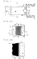
- FIG. 1 is a plan view of a leader tape 5 according to one embodiment of the invention.
- FIG. 2A is a plan view of a portion of the leader tape 5 of a welded area W1 and its vicinity;
- FIG. 2B is a schematic view useful for explaining a welded state of the leader tape 5 welded between a leading end portion 11b and a root portion 11a;
- FIG. 3 is an explanatory view useful in explaining a method of making the leader tape 5;
- FIG. 4A is a side view of a portion of the leader tape 5 along the length thereof where the leading end portion 11b is welded to the root portion 11a by a horn X1;
- FIG. 4B is an enlarged view of a boundary portion S1b appearing in FIG. 4A;
- FIG. 5A is an explanatory view which is useful in explaining a configuration of a boundary portion S1a and its vicinity of the leader tape 5 according to the embodiment;
- FIG. 5B is an explanatory view which is useful in explaining a configuration of a boundary line L11 and its vicinity of a conventional leader tape 35;
- FIG. 6 is a side view of the boundary portion S1b and its vicinity of the leader tape 5;
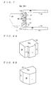
- FIG. 7 is a plan view of a leader tape 15a (15b) according to other embodiments of the invention.
- FIG. 8A is a perspective view of the appearance of a horn X2 used in making the leader tape 15a;
- FIG. 8B is a perspective view of the appearance of a horn X3 used in making the leader tape 15b;
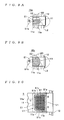
- FIG. 9A is a plan view of a welded area W2 and its vicinity of the leader tape 15a;
- FIG. 9B is a plan view of a welded area W3 and its vicinity of the leader tape 15b;
- FIG. 10 is a plan view of a welded area W1 and its vicinity of the leader tape 5 formed by another welding method
- FIG. 11 is an exploded perspective view of a tape cartridge 1 (and a conventional tape cartridge 31);
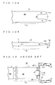
- FIG. 12A is a plan view of a tape body 11
- FIG. 12B is a side view of the tape body 11;
- FIG. 13 is a plan view of the conventional leader tape 35
- FIG. 14 is a plan view of a welded area W11 and its vicinity of the leader tape 35;
- FIG. 15 is a side view of a portion of the leader tape 35 along the length of the leader tape 35 where a leading portion 11b is welded to a root portion 11a by a horn X11;
- FIG. 16 is a side view of the leader tape 35 in a state broken at the boundary line L11;
- FIG. 17A is side view of an edge E1 side portion of the welded area W11 of the leader tape 35.
- FIG. 17B is a side view of the leader tape 35 in a state broken in the vicinity of the edge E1
- the tape cartridge 1 is a one reel-type recording medium cartridge which contains a magnetic tape 4 for use as a backup medium for recording data recorded in a main recording medium of a computer, and is comprised of a cartridge body 2, a reel 3, a magnetic tape 4 and a leader tape 5, as shown in FIG. 11.
- the magnetic tape 4 (see FIG. 1) is actually wound around the reel 3, but in FIG. 11, the illustration of the magnetic tape is omitted.
- the cartridge body 2 is comprised of an upper half 2a and a lower half 2b which are each formed to have a tray shape and can be fitted to each other, and a shutter member 2c which can cover a tape-pulling slot defined by the upper half 2a and the lower half 2b in the state fitted to each other.
- the reel 3 is comprised of an upper flange 3a integrally formed with a hub for having the magnetic tape 4 wound therearound, and a lower flange 3b welded to the hub.
- the leader tape 5 is for pulling the magnetic tape 4 out of the cartridge body 2 containing the same in a state wound around the reel 3, and as shown in FIG. 1, the leader tape 5 includes a tape body(leader tape body) 11, a pin(pin member) 12, and hooks 13, 13. At one end of the tape body 11 on a side where the pin 12 is attached, there are formed leading end portions 11b, 11b in a manner bifurcated from the one end, as shown in FIG. 12A, for being welded to the root portion 11a. Further, the tape body 11 is formed such that the thickness thereof is progressively reduced from the root portion 11a through the leading end portions 11b.
- the thickness T1 of the root portion 11a is set to about 190 ⁇ m, and that of the leading end portions 11b (in the vicinity of its edge E1) to about 100 ⁇ m. Further, as shown in FIG. 1, the leading end portions 11b of the tape body 11 are folded along the periphery of the pin 12 and welded to the root portion 11a whereby the pin 12 is attached to the tape body 11.
- a horn X1 part of which is shown in FIG. 3 is used for welding the leading end portion 11b to the root portion 11a.
- a portion of the horn X1 for being brought into contact with the leading end portion 11b has a width slightly larger than the lateral width of the leading end portion 11b, as shown in FIG. 2A, and a corner opposed to the edge E1 of the tape body 11 and a corner opposed to the pin 12 are each chamfered into an arcuate shape having a radius of about 0.5 mm, as shown in FIG. 3.
- the horn X1 has knurls (not shown) formed on a welding surface (abutment surface via which the horn X11 abuts on the corresponding leading end portion 11b) thereof at a pitch of about 0.6 mm.
- knurls are formed such that the tops thereof are progressively receded with respect to a plane on which the tops of knurls on a central area of the bottom of the horn X11 are arranged in rows.
- the leading end portion 11b of the tape body 11 is brought into contact with the root 11a such that the leading end portion 11b of the tape body 11 surrounds the periphery of the pin 12.
- the horn X1 is brought into contact with the surface of the leading end portion 11b, and ultrasonic waves are delivered from the horn X1 with the leading end portion 11b urged against the root portion 11a.
- the leading end portion 11b and the root portion 11a have their contact surfaces melted and mixed to each other, and the mixed portion solidifies when it cools to normal temperature.
- both the corners of the horn X1 are chamfered such that they form an arcuate shape in cross-section
- welding is effected in portions (boundary portions S1a and S1b, referred to hereinafter) of each leading end portion 11b opposed to the respective corners of the horn X1 such that the opposed portions each form an arcuate shape in cross-section along the length of the tape, as shown in FIG. 4B.
- the opposed portion forms the boundary portions S1a between a welded area W1 where the leading end portion 11b and the root portion 11a are completely welded to each other and a non-welded area V1 where the leading portion 11b and the root portion 11a are completely separate from each other.
- the leading end portion 11b generally progressively comes apart from the root portion 11a toward the pin 12 along an arcuate path protruding toward the tape surface of the opposed root portion 11a and having a radius R1 of about 0.6 mm to 0.8 mm, which is slightly larger than the radius 0.5 mm of the arcuate shape of the corners of the horn X1.
- portions of the boundary portion S1a of the leading end portion 11b corresponding to the respective tops of knurls formed on the horn X1 are brought into abutment with the surface of the root portion 11a in a state protruded toward the root portion 11a by these tops of the knurls. Further, the degree of abutment or contact between the portions of the boundary portion S1a of the leading end portion 11b corresponding to the respective tops of the knurls and the surface of the root portion 11a becomes smaller as the contact point becomes closer to the non-welded area V1. Therefore, in this leader tape 5, as shown in FIG.
- welding is effected in the boundary portion S1a of the leader tape 5 non-densely such that welded portions of the leading end portion 11b and the root portion 11a are formed in a polka-dot pattern by the knurls formed on the both corners of the horn X1.
- the leading end portion 11b and the root portion 11a are welded non-densely, as the location comes closer to the welded area W1, they are welded a little more densely (welded such that dots of the polka-dot pattern are separate from each other, and at the same time larger in size), and as the location comes closer to the pin 12, they are welded a little more non-densely (welded such that dots of the polka-dot patter are separate from each other, and at the same time smaller in size).
- the welding is effected by using the horn X1 having the corners chamfered to form an arcuate shape, in cross-section, which has a radius of 0.5 mm, whereby the cross-section of the boundary portion S1a of the leading end portion 11b has an arcuate shape having a slightly increased radius.
- This makes it possible to prevent stress from being concentrated at the boundary portion S1a. Therefore, the residual stress itself in the boundary portion S1a of the leading end portion 11b can be reduced. As a result, it is possible to effectively prevent the leading end portion 11b from being broken at the boundary portion S1a.
- the welding is effected such that the cross-section along the length of the tape in the boundary portion S1a toward the pin 12 has the arcuate shape protruding toward the opposed tape surface. Therefore, even when the pin 12 is pulled to thereby forcibly expand the juncture angle ⁇ (see FIG. 4A) formed between the welded area of the leading end portion and a non-welded area extending from the welded area toward the pin member 12, stress is not concentrated at one point differently from the prior art but distributed over the whole boundary portion S1a welded to form the arcuate cross-sectional shape. This makes it possible to increase the strength of the tape body against the pulling force, so that breakage at the leading end portion 11b can be positively prevented.
- the conventional leader tape 35 using a conventional horn having a flat welding surface including surfaces of corners a portion of the leading end portion 11b corresponding to a corner of the horn comes apart from the root portion 11a toward the pin 12 along an arcuate path having a radius R11 of about 0. 1 mm due to resilience of the tape body 11 itself.
- the conventional horn has the knurls formed on the flat welding surface, so that all the tops of the knurls are uniformly urged against the leading end portion 11b. This causes the welded area to be formed substantially entirely densely in a polka-dot pattern such that dots of the polka-dot pattern are connected to each other.
- the welded area W11 where the leading end portion 11b and the root portion 11a are completely welded and the non-welded portion where the leading end portion 11b and the root portion 11a are completely separate from each other are divided by the boundary line L11 which is perpendicular to the direction of the length of the tape body 11 and in the form of a straight line. Therefore, as described hereinabove, when the pin 12 is pulled, stress is concentrated at the boundary line L11 in the form of a straight line, so that the leading end portion 11b can be broken due to the pulling force.
- the breakage of the leading end portion 11b can be fully prevented by welding the leading end portion 11b and the root portion 11a to each other such that the leading end portion 11b at the boundary portion S1a comes apart from the root portion 11a along an arcuate path having a radius not smaller than 0.3 mm and not larger than 1.0 mm. Further, it is also confirmed that when the welding is effected such that the arcuate path has a radius of less than 0.3 mm, the leading end portion 11b is liable to breakage similarly to the conventional leader tape 35.
- a leader tape can be made which is capable of fully preventing the breakage due to the pulling force and the falling-off of the pin 12, by welding the leading end portion 11b and the root portion 11a to each other such that the cross-section of the boundary portion S1a (or portion from the boundary portion S1a to the non-welded area V1) forms an arcuate path having a radius not smaller than 0.3 mm and not larger than 1.0 mm.
- the corner of the horn X1 opposed to the edge E1 is chamfered into an arcuate shape in cross-section similarly to the other corner of the same toward the pin 12. Therefore, as shown in FIG. 6, the leading end portion 11b and the root portion 11a are welded such that the cross-section of a portion of the leading end portion 11b on the side of the edge E11 has a shape forming an arcuate path protruding toward the tape surface of the root portions 11a. More specifically, the welding is carried out such that the portion of the leading end portion 11b on the side of the edge E1 forms an arcuate path to the edge E1 which has a radius R2 of about 0.8 mm.
- the welding is performed non-densely similarly to the boundary portion S1a.
- the boundary portion S1b similarly to the boundary portion S1a, since the corners of the horn X1 are chamfered, during the welding process, the tape surface of the boundary portion S1b and the tops of the knurls are progressively or increasingly separated, as the location comes closer to the edge E1.
- the leading end portion 11b and the root portion 11a are welded non-densely, as the location comes closer to the welded area W1, they are welded a little more densely, (welded such that the dots of the polka-dot pattern are separate from each other, and at the same time larger in size), while as the location comes closer to the edge E1, they are welded more non-densely (welded such that the dots of the polka-dot pattern are separate from each other, and at the same time smaller in size). Therefore, in the leader tape 5, when the pin 12 is pulled, the stress applied to the root portion 11a is distributed in a somewhat wider range of area along the direction of tape length, i.e.
- the boundary portion S1b where the welding is effected non-densely. This prevents the stress from being concentrated at a particular portion, whereby differently from the conventional leader tape 35, the breakage of the root portion 11a due to the pulling force can be prevented.
- the boundary portion S1b similarly to the boundary portion S1a, since the corners of the horn X1 are chamfered, it is possible to prevent stress from being concentrated at the boundary portion S1b during the welding process. Therefore, the residual stress itself in the boundary area S1b of the edge E1 can be reduced. As a result, it is possible to effectively prevent the root portion 11a from being broken at the edge E1.
- leader tapes 15a, 15b according to other embodiments of the invention will be described with reference to drawings.
- FIG. 7 shows the leader tape 15a (or 15b) with which the magnetic tape 4 is pulled out of the cartridge body 2 similarly to the leader tape 5, and the leader tape 15a (15b) includes a tape body 11, a pin 12, and hooks 13, 13.
- the leader tape 15a (15b) is made by using a horn X2 (or X3) shown in FIG. 8A (or 8B) when the welding of the leading end portion 11b and the root portion 11a is carried out.
- the horn X2 (or X3) is protruded in plan view (welding surface has a protruded shape in plan view), and a corner of the horn X2 (or X3) opposed to the edge E1 of the tape body 11 is chamfered into an arcuate shape similarly to that of the horn X1.
- this leader tape 15a (or 15b)
- a welded area W2(or W3) where the leading end portion 11b and the root portion 11a are completely welded to each other and a non-welded area V1 where the leading end portion 11b and the root portion 11a are completely separate from each other are divided by a protruded boundary line.
- the leading end portion 11b and the root portion 11a are welded to each other such that the boundary line L2 (or L3) dividing between the welded area W2 (or W3) and the non-welded area V1 is protruded in a central portion thereof toward the pin 12. Therefore, in the leader tape 15a (or 15b), the length of the boundary line L2 (or L3) becomes longer than the boundary line L1 which is in the form of a straight line perpendicular to the direction of the length of the tape, so that the force applied to the leading end portion 11b to pull out the magnetic tape 4 is distributed to a wider range of area by the increased boundary line.
- the present invention is not limited to the above embodiments, but the construction thereof can be modified as required.
- the horn X1 having both of the corners opposed to the edge E1 and the corner toward the pin 12 are chamfered is used for welding, this is not limitative, but a horn having either of the corners chamfered into the arcuate shape may be used for welding.
- the welding may be effected non-densely in boundary portions S1c, S1c between the lateral side edges of the leading end portion 11b and the root portion 11a.
- boundary portions S1a, S1b, S1c, S1c may be provided on all the boundary areas between the non-welded area V1 and the welded area W1.
- this construction it is possible to further increase the strength of the leader tape 5 against the breakage thereof.
- leader tapes 15a, 15b the description was given of the example using the horns X2, X3 which are protruded in plan view, it is also possible to use a horn which is recessed in plan view to thereby form a boundary between the welded area W1 and the non-welded area V1 such that the boundary is recessed on a side facing toward the pin 12.
- This configuration can also increase the strength of the leader tape 5 against breakage.
- the configuration of the horn may be defined such that the boundary line of the welded area W1 has any of various non-linear shapes, including shapes of a polygonal line, a curve, and a wavy line.
- the object to which the present leader tape is attached is not limited to the magnetic tape for data recording, but it may be any of various tapes, including a cleaning tape.
- the method of welding the leading end portion 11b and the root portion 11a to each other is not limited to the method using the ultrasonic waves, but it is possible to employ a welding tool using heat generated by a heater.
Landscapes
- Engineering & Computer Science (AREA)
- Mechanical Engineering (AREA)
- Replacement Of Web Rolls (AREA)
- Packaging Of Annular Or Rod-Shaped Articles, Wearing Apparel, Cassettes, Or The Like (AREA)
- Lining Or Joining Of Plastics Or The Like (AREA)
Abstract
Description
Claims (10)
- A leader tape including a leader tape body having one end fixed to a tape, for enabling the tape to be pulled out of a cartridge body, and a pin member attached to the leader tape body, for pulling out the tape therewith, the leader tape body having a portion thereof on a side of another end opposite to the one end, the portion being folded such that the folded portion surrounds a periphery of the pin member and that the folded portion has a leading end portion thereof welded to a tape surface of the leader tape body opposed to the folded portion,
wherein welding is effected non-densely in at least one of a pin member-side boundary portion of a welded area where the folded leading end portion and the tape surface opposed thereto are welded to each other and a one end-side boundary portion of the welded area. - A leader tape according to claim 1, wherein in the at least one of the pin member-side boundary portion and the one end-side boundary portion, welded portions are formed in at least one of a polka-dot pattern, a spotted pattern, and a mesh pattern.
- A leader tape including a leader tape body having one end fixed to a tape, for enabling the tape to be pulled out of a cartridge body, and a pin member attached to the leader tape body, for pulling out the tape therewith, the leader tape body having a portion thereof on a side of another end opposite to the one end, the portion being folded such that the folded portion surrounds a periphery of the pin member and that the folded portion has a leading end portion thereof welded to a tape surface of the leader tape body opposed to the folded portion,
wherein welding of the folded leading end portion is effected such that at least one of a pin member-side boundary portion of a welded area where the folded leading end portion and the tape surface opposed thereto are welded to each other and a one end-side boundary portion of the welded area forms an arcuate shape in cross-section along a tape length, the arcuate shape protruding toward the tape surface opposed thereto. - A leader tape according to claim 3, wherein the arcuate shape has a radius not smaller than 0.3 mm and not larger than 1.0 mm.
- A leader tape including a leader tape body having one end fixed to a tape, for enabling the tape to be pulled out of a cartridge body, and a pin member attached to the leader tape body, for pulling out the tape therewith, the leader tape body having a portion thereof on a side of another end opposite to the one end, the portion being folded such that the folded portion surrounds a periphery of the pin member and that the folded portion has a leading end portion thereof welded to a tape surface of the leader tape body opposed to the folded portion,
wherein welding of the leader tape body is effected such that at least one of a pin member-side boundary of a welded area where the folded leading end portion and the tape surface opposed thereto are welded to each other and a one end-side boundary of the welded area forms a protruded shape having a central portion thereof protruded toward the pin member or a recessed shape having a central portion thereof recessed in a direction away from the pin member. - A tape cartridge comprising:a cartridge body;a tape;a leader tape fixedly attached to said tape, said leader tape including a leader tape body having one end fixed to said tape, for enabling the tape to be pulled out of a cartridge body, and a pin member attached to said leader tape body, for pulling out said tape therewith, said leader tape body having a portion thereof on a side of another end opposite to the one end, the portion being folded such that the folded portion surrounds a periphery of said pin member and that the folded portion has a leading end portion thereof welded to a tape surface of said leader tape body opposed to the folded portion, welding being effected non-densely in at least one of a pin member-side boundary portion of a welded area where the folded leading end portion and the tape surface opposed thereto are welded to each other and a one end-side boundary portion of the welded area; anda reel received in said cartridge body, with said tape having said leader tape fixedly attached thereto being wound therearound.
- A tape cartridge according to claim 6, wherein in the at least one of the pin member-side boundary portion and the one end-side boundary portion of the welded area, welded portions are formed in at least one of a polka-dot pattern, a spotted pattern, and a mesh pattern.
- A tape cartridge comprising:a cartridge body;a tape;a leader tape fixedly attached to said tape, said leader tape including a leader tape body having one end fixed to said tape, for enabling the tape to be pulled out of a cartridge body, and a pin member attached to said leader tape body, for pulling out said tape therewith, said leader tape body having a portion thereof on a side of another end opposite to the one end, the portion being folded such that the folded portion surrounds a periphery of said pin member and that the folded portion has a leading end portion thereof welded to a tape surface of said leader tape body opposed to the folded portion, welding of the folded leading end portion being effected such that at least one of a pin member-side boundary portion of a welded area where the folded leading end portion and the tape surface opposed thereto are welded to each other and a one end-side boundary portion of the welded area forms an arcuate shape in cross-section along a tape length, the arcuate shape protruding toward the tape surface opposed thereto; anda reel received in said cartridge body, with said tape having said leader tape fixedly attached thereto being wound therearound.
- A leader tape according to claim 8, wherein the arcuate shape has a radius not smaller than 0.3 mm and not larger than 1.0 mm.
- A tape cartridge comprising:a cartridge body;a tape;a leader tape fixedly attached to said tape, said leader tape including a leader tape body having one end fixed to said tape, for enabling said tape to be pulled out of a cartridge body, and a pin member attached to said leader tape body, for pulling out said tape therewith, said leader tape body having a portion thereof on a side of another end opposite to the one end, the portion being folded such that the folded portion surrounds a periphery of said pin member and that the folded portion has a leading end portion thereof welded to a tape surface of said leader tape body opposed to the folded portion, welding of said leader tape body being effected such that at least one of a pin member-side boundary of a welded area where the folded leading end portion and the tape surface opposed thereto are welded to each other and a one end-side boundary of the welded area forms a protruded shape having a central portion thereof protruded toward said pin member or a recessed shape having a central portion thereof recessed in a direction away from said pin member; anda reel received in said cartridge body, with said tape having said leader tape fixedly attached thereto being wound therearound.
Applications Claiming Priority (2)
| Application Number | Priority Date | Filing Date | Title |
|---|---|---|---|
| JP2001128518A JP2002324377A (en) | 2001-04-26 | 2001-04-26 | Leader tape |
| JP2001128518 | 2001-04-26 |
Publications (2)
| Publication Number | Publication Date |
|---|---|
| EP1253591A2 true EP1253591A2 (en) | 2002-10-30 |
| EP1253591A3 EP1253591A3 (en) | 2006-04-12 |
Family
ID=18977194
Family Applications (1)
| Application Number | Title | Priority Date | Filing Date |
|---|---|---|---|
| EP02009237A Withdrawn EP1253591A3 (en) | 2001-04-26 | 2002-04-25 | Leader tape and tape cartridge |
Country Status (3)
| Country | Link |
|---|---|
| US (1) | US6655623B2 (en) |
| EP (1) | EP1253591A3 (en) |
| JP (1) | JP2002324377A (en) |
Cited By (1)
| Publication number | Priority date | Publication date | Assignee | Title |
|---|---|---|---|---|
| GB2408141A (en) * | 2003-11-13 | 2005-05-18 | Hitachi Maxell | Single-reel type tape cartridge |
Families Citing this family (5)
| Publication number | Priority date | Publication date | Assignee | Title |
|---|---|---|---|---|
| JP2004253014A (en) * | 2003-02-18 | 2004-09-09 | Tdk Corp | Disk cartridge |
| US7274528B2 (en) * | 2005-03-17 | 2007-09-25 | Certance Llc | System and method for protecting head elements of a tape drive |
| US20060214042A1 (en) * | 2005-03-28 | 2006-09-28 | Tdk Corporation | Tape reel, cartridge case, information recording medium, and molding mold |
| JP2007335009A (en) * | 2006-06-15 | 2007-12-27 | Fujifilm Corp | Tape cartridge |
| US20120287535A1 (en) * | 2011-05-09 | 2012-11-15 | Saliba Innovations, Llc | Wavy Lapping Tape for Repair of Negative Pressure Tape Head |
Family Cites Families (9)
| Publication number | Priority date | Publication date | Assignee | Title |
|---|---|---|---|---|
| AT307074B (en) * | 1970-06-05 | 1973-05-10 | Philips Nv | Method for connecting one end of a single-coated magnetic tape having a plastic carrier with one end of a pretensioning tape made of plastic and device for carrying out the method |
| AU675937B2 (en) * | 1992-04-10 | 1997-02-27 | W.L. Gore & Associates, Inc. | A method of ultrasonically welding articles of porous polytetrafluoroethylene |
| US5971310A (en) * | 1998-09-08 | 1999-10-26 | Quantum Corporation | Positive engagement buckle for a tape drive and cartridge |
| EP1083565B1 (en) * | 1999-09-08 | 2007-12-12 | Quantum Corporation | Tape cartridge |
| DE10027190A1 (en) * | 1999-10-06 | 2001-04-12 | Hewlett Packard Co | Tape for data storage is provided with a specified length of a flexible guide element which for strengthening purposes is superimposed at least on one of the two tape ends |
| JP4393727B2 (en) * | 2000-06-01 | 2010-01-06 | 日立マクセル株式会社 | Single reel type magnetic tape cartridge |
| JP4386310B2 (en) | 2000-06-13 | 2009-12-16 | 日立マクセル株式会社 | Single reel type magnetic tape cartridge |
| US6375108B1 (en) * | 2000-07-13 | 2002-04-23 | Quantum Corporation | Multi-layered drive leader for a tape drive |
| EP1303340A2 (en) * | 2000-07-27 | 2003-04-23 | Lydall, Inc. | Unitary multi-component filter media |
-
2001
- 2001-04-26 JP JP2001128518A patent/JP2002324377A/en active Pending
-
2002
- 2002-04-24 US US10/128,304 patent/US6655623B2/en not_active Expired - Fee Related
- 2002-04-25 EP EP02009237A patent/EP1253591A3/en not_active Withdrawn
Cited By (3)
| Publication number | Priority date | Publication date | Assignee | Title |
|---|---|---|---|---|
| GB2408141A (en) * | 2003-11-13 | 2005-05-18 | Hitachi Maxell | Single-reel type tape cartridge |
| GB2408141B (en) * | 2003-11-13 | 2007-05-30 | Hitachi Maxell | Single-reel type tape cartridge |
| US7967931B2 (en) | 2003-11-13 | 2011-06-28 | Hitachi Maxell, Ltd. | Single-reel type tape cartridge |
Also Published As
| Publication number | Publication date |
|---|---|
| JP2002324377A (en) | 2002-11-08 |
| US20020162911A1 (en) | 2002-11-07 |
| EP1253591A3 (en) | 2006-04-12 |
| US6655623B2 (en) | 2003-12-02 |
Similar Documents
| Publication | Publication Date | Title |
|---|---|---|
| US6655623B2 (en) | Leader tape and tape cartridge | |
| US7967931B2 (en) | Single-reel type tape cartridge | |
| JP3239401B2 (en) | Tape cassette | |
| US6028741A (en) | Magnetic head device which is capable of controlling a shift of a head main body | |
| JPH0743814Y2 (en) | Magnetic tape cartridge | |
| EP0379117B1 (en) | Magnetic disk cartridge | |
| JPH08138343A (en) | Tape cassette | |
| JP3723356B2 (en) | Single reel type magnetic tape cartridge | |
| JPS60197985A (en) | Disk cartridge | |
| JPH08203242A (en) | Tape cassette | |
| JP3552428B2 (en) | Tape reel | |
| US20120067999A1 (en) | Tape reel and information recording medium | |
| JP2581401Y2 (en) | cassette | |
| JP3103098U (en) | Magnetic head | |
| JP2592598Y2 (en) | Tape cassette | |
| JPH01105372A (en) | Magnetic disk housing case | |
| JP3783717B2 (en) | Sliding magnetic head for magneto-optical recording | |
| JPH0636508A (en) | Tape cassette | |
| JPH11353848A (en) | Magnetic tape cartridge | |
| JPS60170010A (en) | magnetic head | |
| JP4057999B2 (en) | Flex cable assembly (FCA), head gimbal assembly (HGA), and disk drive | |
| JPH10211984A (en) | Storage case for tape cassette | |
| JPS61190459A (en) | Electronic part run | |
| JP2006228296A (en) | Tape reel and tape cartridge provided with the same | |
| JPH0664692B2 (en) | Magnetic head manufacturing method |
Legal Events
| Date | Code | Title | Description |
|---|---|---|---|
| PUAI | Public reference made under article 153(3) epc to a published international application that has entered the european phase |
Free format text: ORIGINAL CODE: 0009012 |
|
| 17P | Request for examination filed |
Effective date: 20020524 |
|
| AK | Designated contracting states |
Kind code of ref document: A2 Designated state(s): AT BE CH CY DE DK ES FI FR GB GR IE IT LI LU MC NL PT SE TR |
|
| AX | Request for extension of the european patent |
Free format text: AL;LT;LV;MK;RO;SI |
|
| PUAL | Search report despatched |
Free format text: ORIGINAL CODE: 0009013 |
|
| AK | Designated contracting states |
Kind code of ref document: A3 Designated state(s): AT BE CH CY DE DK ES FI FR GB GR IE IT LI LU MC NL PT SE TR |
|
| AX | Request for extension of the european patent |
Extension state: AL LT LV MK RO SI |
|
| RAP1 | Party data changed (applicant data changed or rights of an application transferred) |
Owner name: QUANTUM CORPORATION |
|
| 17Q | First examination report despatched |
Effective date: 20061115 |
|
| AKX | Designation fees paid |
Designated state(s): DE GB |
|
| STAA | Information on the status of an ep patent application or granted ep patent |
Free format text: STATUS: THE APPLICATION IS DEEMED TO BE WITHDRAWN |
|
| 18D | Application deemed to be withdrawn |
Effective date: 20100122 |