JP2004253014A - Disk cartridge - Google Patents
Disk cartridge Download PDFInfo
- Publication number
- JP2004253014A JP2004253014A JP2003039135A JP2003039135A JP2004253014A JP 2004253014 A JP2004253014 A JP 2004253014A JP 2003039135 A JP2003039135 A JP 2003039135A JP 2003039135 A JP2003039135 A JP 2003039135A JP 2004253014 A JP2004253014 A JP 2004253014A
- Authority
- JP
- Japan
- Prior art keywords
- disk
- opening
- shutter member
- cartridge
- tray
- Prior art date
- Legal status (The legal status is an assumption and is not a legal conclusion. Google has not performed a legal analysis and makes no representation as to the accuracy of the status listed.)
- Pending
Links
- 230000003287 optical effect Effects 0.000 abstract description 69
- 238000004519 manufacturing process Methods 0.000 abstract description 10
- 230000001105 regulatory effect Effects 0.000 description 6
- 238000005192 partition Methods 0.000 description 5
- 210000000078 claw Anatomy 0.000 description 3
- 230000002093 peripheral effect Effects 0.000 description 3
- 230000000694 effects Effects 0.000 description 1
- 238000000034 method Methods 0.000 description 1
- 230000002265 prevention Effects 0.000 description 1
Images


Classifications
-
- G—PHYSICS
- G11—INFORMATION STORAGE
- G11B—INFORMATION STORAGE BASED ON RELATIVE MOVEMENT BETWEEN RECORD CARRIER AND TRANSDUCER
- G11B23/00—Record carriers not specific to the method of recording or reproducing; Accessories, e.g. containers, specially adapted for co-operation with the recording or reproducing apparatus ; Intermediate mediums; Apparatus or processes specially adapted for their manufacture
- G11B23/02—Containers; Storing means both adapted to cooperate with the recording or reproducing means
- G11B23/03—Containers for flat record carriers
- G11B23/0301—Details
- G11B23/0308—Shutters
-
- G—PHYSICS
- G11—INFORMATION STORAGE
- G11B—INFORMATION STORAGE BASED ON RELATIVE MOVEMENT BETWEEN RECORD CARRIER AND TRANSDUCER
- G11B23/00—Record carriers not specific to the method of recording or reproducing; Accessories, e.g. containers, specially adapted for co-operation with the recording or reproducing apparatus ; Intermediate mediums; Apparatus or processes specially adapted for their manufacture
- G11B23/02—Containers; Storing means both adapted to cooperate with the recording or reproducing means
- G11B23/03—Containers for flat record carriers
- G11B23/0301—Details
- G11B23/0313—Container cases
-
- G—PHYSICS
- G11—INFORMATION STORAGE
- G11B—INFORMATION STORAGE BASED ON RELATIVE MOVEMENT BETWEEN RECORD CARRIER AND TRANSDUCER
- G11B23/00—Record carriers not specific to the method of recording or reproducing; Accessories, e.g. containers, specially adapted for co-operation with the recording or reproducing apparatus ; Intermediate mediums; Apparatus or processes specially adapted for their manufacture
- G11B23/02—Containers; Storing means both adapted to cooperate with the recording or reproducing means
- G11B23/03—Containers for flat record carriers
- G11B23/0301—Details
- G11B23/0317—Containers with interchangeable record carriers
Abstract
Description
【0001】
【発明の属する技術分野】
本発明は、下シェルおよび上シェルを備えて構成されたカートリッジ本体内にディスク状記録媒体が収容されるディスクカートリッジに関するものである。
【0002】
【従来の技術】
この種のディスクカートリッジとして、上シェル(13)、中シェル(14)および下シェル(15)からなるカートリッジ筐体(12)内に光ディスク(11)が収容されたディスクカートリッジ(10)が特開2002−50147号公報に開示されている。この場合、中シェルは、全体として円板状に形成されると共に、その周面(リング部14b)には、記録再生装置のシャッタ開閉手段が噛合可能なギア等からなる被操作部(43)が形成されている。また、中シェルは、上シェルおよび下シェルによって形成される箱体内に回動可能に収容されている。また、中シェルおよび下シェルには、収容状態の光ディスクに対する記録データの記録および再生(ディスクアクセス)を可能とする開口部(42,25)が形成されて、この開口部が一対のシャッタ部材(18a,18b)によって開閉される。この場合、シャッタ部材は、全体として薄板状に形成されると共に、中シェルの支持孔(49)に挿通させられる軸部(52)と、下シェルの操作凸部(27a,27b)が挿通させられる開閉溝(53)とが形成されて構成されている。また、シャッタ部材は、下シェルに対して中シェルが回動させられることで中シェルによってスライドさせられて、下シェルおよび中シェルの開口部(25,42)を開閉する。
【0003】
このディスクカートリッジでは、常態において、下シェルの開口部が一対のシャッタ部材と中シェルとによって閉塞されている。また、このディスクカートリッジが記録再生装置に装填された際には、記録再生装置のシャッタ開閉手段によって中シェルが回動させられる。この際には、下シェルの開口部と中シェルの開口部とがディスクカートリッジの厚み方向で重ね合わされると共に、シャッタ部材が中シェルの回動に伴って互いに離間する方向にスライドさせられる。この結果、下シェルの開口部が開口されて、ディスクカートリッジ内の光ディスクに対するディスクアクセスが可能な状態となる。一方、ディスクカートリッジを記録再生装置から取り出す際には、記録再生装置のシャッタ開閉手段によって中シェルが装填時とは逆向きに回動させられる。この際に、下シェルおよび中シェルの両開口部の重なり合いが解除されると共に、シャッタ部材が中シェルの回動に伴って互いに接近する方向にスライドさせられて開口部が閉塞される。以上により、光ディスクに対するディスクアクセスの要否に応じて開口部が開口または閉塞される。
【0004】
【特許文献1】
特開2002−50147号公報(第3−11頁)
【0005】
【発明が解決しようとする課題】
ところが、従来のディスクカートリッジには、以下の問題点がある。すなわち、このディスクカートリッジでは、記録再生装置のシャッタ開閉手段によって中シェルが回動させられることより、中シェルが下シェルに対して一対のシャッタ部材をスライドさせて開口部を開口または閉塞させている。この場合、中シェルが回動させられた際には、両シャッタ部材の軸部が中シェルの支持孔内で回動させられると共に、下シェルの操作凸部が両シャッタ部材の開閉溝内を相対的にスライドさせられる。したがって、両シャッタ部材の開閉に際しては、中シェルにおける支持孔の口縁部とシャッタ部材における軸部の周面との間の摺動抵抗、およびシャッタ部材における開閉溝の口縁部と下シェルにおける操作凸部の周面との間の摺動抵抗などに起因して、中シェルの回動(すなわち、シャッタ部材の開閉)に大きな力を必要とする。このため、従来のディスクカートリッジには、シャッタ部材のスムーズな開閉動作が困難であるという問題点が存在する。また、カートリッジ筐体内に2枚のシャッタ部材を配設しているため、従来のディスクカートリッジには、ディスクカートリッジの組み立てが煩雑な結果、製造コストが高騰しているという問題点もある。
【0006】
本発明は、かかる問題点に鑑みてなされたものであり、製造コストの低減を図りつつ、シャッタ部材をスムーズに開閉させ得るディスクカートリッジを提供することを主目的とする。
【0007】
【課題を解決するための手段】
上記目的を達成すべく本発明に係るディスクカートリッジは、収容状態のディスク状記録媒体に対するディスクアクセスを可能とする第1開口部が形成された下シェル、および上シェルを備えて構成されたカートリッジ本体と、前記ディスク状記録媒体を載置可能に形成されて前記カートリッジ本体内に回動可能に配設されたディスクトレイと、前記下シェルおよび前記ディスクトレイの間に配設された単一のシャッタ部材とを備え、前記ディスクトレイは、前記第1開口部と当該ディスクカートリッジの厚み方向において重ね合わされることによって前記ディスク状記録媒体に対するディスクアクセスを可能とする第2開口部が形成されて、前記ディスクアクセスを規制する規制状態では当該第1開口部の一部を閉塞し、前記ディスクアクセスの状態では前記カートリッジ本体内で回動させられて前記シャッタ部材をスライドさせると共に前記第1開口部の前記一部を開口可能に構成され、前記シャッタ部材は、前記規制状態では前記第1開口部における他の一部を閉塞することによって前記ディスクトレイと相俟って当該第1開口部を閉塞し、前記ディスクアクセスの状態では前記ディスクトレイによってスライドさせられることによって前記他の一部を開口可能に構成されている。
【0008】
この場合、前記シャッタ部材は、回動可能にその一端部が前記下シェルに軸支されると共に案内溝およびピン部材のいずれか一方が形成されて構成され、前記ディスクトレイは、前記案内溝および前記ピン部材のいずれか他方が形成されると共に、前記ディスクアクセスの際に回動させられて前記案内溝によって前記ピン部材が案内されることで前記一端部を中心とする円弧状の軌跡で回動させて前記シャッタ部材をスライド可能に構成されているのが好ましい。
【0009】
また、前記シャッタ部材は、前記第1開口部を閉塞する閉塞位置において前記ディスク状記録媒体を保持するために当該ディスク状記録媒体の外縁部に当接すると共に前記第1開口部を開口する開口位置において前記ディスク状記録媒体に対する前記当接を解除するディスク保持部を備えて構成されているのが好ましい。
【0010】
さらに、前記上シェルは、前記カートリッジ本体に対する前記ディスク状記録媒体の取り外しおよび収納を可能にする略円形状のディスク入出口が形成されて構成され、前記シャッタ部材は、前記第1開口部を閉塞する閉塞位置において前記ディスク状記録媒体の中心孔に対向する部位に当該中心孔よりも大径の孔が形成されているのが好ましい。
【0011】
【発明の実施の形態】
以下、添付図面を参照して、本発明に係るディスクカートリッジの好適な実施の形態について説明する。
【0012】
最初に、ディスクカートリッジ1の構成について、図面を参照して説明する。
【0013】
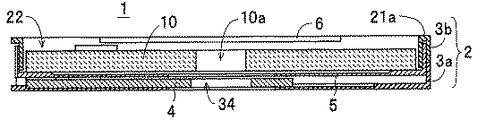
図1,2に示すディスクカートリッジ1は、光ディスク10を取り出し可能に収容したカートリッジ式の記録媒体であって、カートリッジ本体2、単一のシャッタ部材4、ディスクトレイ5および上動規制板6を備えると共に、図11にそれぞれ示す保持片7、回動規制部材8および誤消去防止部材9を備えて構成されている。なお、図2および後に参照する図4,6,8,10では、本発明についての理解を容易とするために、厚み方向のサイズを誇張して大きく図示している。光ディスク10は、一例として、片面追記型のディスク状記録媒体であって、図1,2に示すように、その中心部には、記録再生装置(本発明におけるディスクドライブの一例)にチャッキングさせるための直径15mm程度の中心孔10aが形成されている。一方、図2に示すように、カートリッジ本体2は、互いに嵌合可能に形成された下シェル3aおよび上シェル3bを備えている。
【0014】
下シェル3aは、図3,4に示すように、開口部12(本発明における第1開口部)が形成された底板11aと、底板11aの外縁部に立設されてディスクカートリッジ1の側面部分を構成する側壁11bとで浅皿状に形成されている。この場合、開口部12は、記録データの記録再生時にカートリッジ本体2内に収容されている光ディスク10に対するディスクアクセス(記録再生装置によるチャッキングや、ピックアップによるレーザービームの照射等)を可能とする孔であって、光ディスク10の中心部から外縁部までを露出可能な大きさに形成されている。また、底板11aには、シャッタ部材4の移動範囲に相当する部位を薄肉に形成して凹部13が形成され、この凹部13には、シャッタ部材4を回動可能に軸支するための凸部14が立設されている。また、底板11aには、シャッタ部材4と相俟って光ディスク10を保持する保持片7を取り付けるための凹部15が形成されている。
【0015】
上シェル3bは、図5,6に示すように、略円形状の開口部22(本発明におけるディスク入出口)が形成された天板21aと、天板21aの外縁部に立設されて下シェル3aの側壁11bと相俟ってディスクカートリッジ1の側面部分を構成する側壁21bと、開口部22の口縁部に立設された隔壁23とを備えて構成されている。この場合、開口部22は、カートリッジ本体2内に収容された光ディスク10のカートリッジ本体2外への取り出し、およびカートリッジ本体2内への収容を可能とする孔であって、その一部において天板21aを内側に突出形成することで、カートリッジ本体2に収容されている光ディスク10の上動を規制するための上動規制部24が形成されている。また、天板21aには、上動規制部24と相俟って光ディスク10の上動を規制する上動規制板6を取り付けるための鍔部25a,25aを有する取付部25が形成されている。さらに、隔壁23には、保持片7、およびシャッタ部材4の保持部35(図7,8参照)を隔壁23の内側に進入可能とするための切り欠き23a,23bが形成されている。
【0016】
シャッタ部材4は、図7,8に示すように、その一端部に下シェル3aの凸部14が挿通可能な孔32が形成された平板状のシャッタ本体31と、光ディスク10の外縁部に当接して保持片7と相俟って光ディスク10を保持するディスク保持部(以下、「保持部」ともいう)35とを備えて構成され、図2に示すように、下シェル3aとディスクトレイ5との間に挟み込まれるようにしてカートリッジ本体2内に配設されている。この場合、シャッタ本体31には、ディスクトレイ5の下面に立設された凸部46(図9参照)が挿通可能なスリット33(本発明における案内溝)が形成されている。また、シャッタ本体31には、後述する閉塞位置にシャッタ部材4が位置させられた状態において光ディスク10の中心孔10aと対向する部位に、中心孔10aよりも大径の(一例として直径17mm)孔34が形成されている。
【0017】
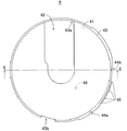
ディスクトレイ5は、図9,10に示すように、下シェル3aの開口部12とほぼ同形状の開口部42(本発明における第2開口部)が形成された円板状の底板41と、底板41の外縁部に立設された側壁43とで光ディスク10を載置可能な浅皿状に形成されている。このディスクトレイ5は、図2に示すように、光ディスク10と共にカートリッジ本体2内に回動可能に収容されている。この場合、図9に示すように、底板41の下面には、シャッタ部材4のスリット33に挿通させられる凸部46(本発明におけるピン部材)が立設されている。また、側壁43には、記録再生装置におけるシャッタ開閉手段(図示せず)が噛合可能な噛合用凹部44a,44bおよび噛合用凸部45,45・・が形成されている。さらに、図9,10に示すように、側壁43には、上シェル3bの隔壁23に形成された切り欠き23a,23bに対してディスクカートリッジ1の平面方向において重なり合うようにして、切り欠き23a,23b内に進入させられた保持片7、およびシャッタ部材4の保持部35をディスクトレイ5上の光ディスク10における外縁部に当接可能とするための切り欠き43a,43bが形成されている。
【0018】
上動規制板6は、図2に示すように、上シェル3bに取り付けた状態においてその表面が天板21aの表面と面一となるように平板状に形成されている。また、図11,12に示すように、上動規制板6は、その両側部に上シェル3bに取り付けるためのフランジ51,51が形成されると共に、上シェル3bに対してスライドさせられた際に下シェル3aの側壁11bにおける内面に当接して上動規制板6のスライドを停止させるストッパ52,52が立設されている。この上動規制板6は、図1に示すように、その一辺(一端面)が上シェル3bにおける開口部22の内側に突出するように位置させられることにより、上動規制部24と相俟ってカートリッジ本体2に収容されている状態の光ディスク10の上動を規制する。保持片7は、図11に示すように、下シェル3aに取り付けるための柱状部62が立設された主板61に、光ディスク10の外縁部に当接する保持板63が立設されている。この保持片7は、その柱状部62が下シェル3aの凹部15に回動可能に取り付けられて主板61および保持板63がスプリングS1によって図14に示す矢印L2の向きに付勢されている。この場合、保持片7は、光ディスク10に対するディスクアクセスを規制する常態(規制状態)においてはディスクトレイ5の切り欠き43a内(図10参照)に進入させられて保持板63が光ディスク10の外縁部に当接させられることにより、光ディスク10をカートリッジ本体2内に保持する。また、後述するように、ディスクトレイ5の回動時には、主板61にディスクトレイ5の側壁43が当接することによって図13に示す矢印L1の向きに回動させられて、保持板63による光ディスク10の保持を解除する。
【0019】
回動規制部材8は、図11に示すように、下シェル3aに対して回動可能に取り付けるための柱状部65と、ディスクトレイ5の噛合用凹部44bに係合することによってディスクトレイ5の回動を規制するための爪部66と、ディスクカートリッジ1が記録再生装置に装填された際にシャッタ開閉手段が当接させられる当接部67とを備えて構成されている。この回動規制部材8は、図13に示すように、スプリングS2によって爪部66がディスクトレイ5の噛合用凹部44bに係合する向きに付勢されてディスクトレイ5の回動を規制する。また、ディスクカートリッジ1が記録再生装置に装填された際には、シャッタ開閉手段が当接部67に当接することによって柱状部65を中心として爪部66が側壁43から離間する向きに回動させられてディスクトレイ5に対する回動の規制を解除する。誤消去防止部材9は、図13に示すように、カートリッジ本体2に取り付けられて、ディスクカートリッジ1に対する記録データの記録(または、記録データの消去)を可能とする解除位置と、記録データの記録(または、記録データの消去)を規制する規制位置との間でスライドさせられる。
【0020】
次に、ディスクカートリッジ1の使用方法について、図面を参照して説明する。
【0021】
このディスクカートリッジ1では、図13に示すように、記録再生装置から取り外されている状態において、下シェル3aの開口部12が、ディスクトレイ5の底板41とシャッタ部材4のシャッタ本体31とによって閉塞されている。具体的には、ディスクトレイ5は、その開口部42と下シェル3aの開口部12とがディスクカートリッジ1の厚み方向において重なり合う位置(以下、この位置を「開口位置」ともいう)から図13において反時計方向(左向き)に45°程度回動させられた状態に位置させられている。これにより、開口部12の開放端側(光ディスク10の外縁部側に対するディスクアクセスを可能とする部位)がディスクトレイ5の底板41によって閉塞されている(以下、開口部12の開放端側を閉塞する位置を「閉塞位置」ともいう)。なお、同図および図14,15では、本発明の理解を容易とするために光ディスク10および上シェル3bの図示を省略する。また、シャッタ部材4は、その孔34が光ディスク10の中心孔10aと重なり合う位置に位置させられている。したがって、開口部12におけるカートリッジ本体2の中心部側の端部がシャッタ本体31によって閉塞されている(以下、開口部12における中心部側の端部を閉塞する位置を「閉塞位置」ともいう)。このように、このディスクカートリッジ1では、常態において、開口部12がディスクトレイ5の底板41とシャッタ部材4のシャッタ本体31とによって閉塞されている。
【0022】
また、このディスクカートリッジ1では、常態において、保持片7と、シャッタ部材4の保持部35とがディスクトレイ5の切り欠き43a,43b内にそれぞれ進入して、保持片7および保持部35が、光ディスク10を挟持するようにして保持している。したがって、カートリッジ本体2内での光ディスク10のがたつきが回避されている。また、カートリッジ本体2内に収容された光ディスク10は、図1に示すように、上シェル3bの上動規制部24と上動規制板6とによって上方への離脱が規制されている。
【0023】
一方、ディスクカートリッジ1を記録再生装置に装填した際には、ディスクカートリッジ1が記録再生装置によって装置内部に引き込まれる。この際には、記録再生装置のシャッタ開閉手段によってディスクトレイ5が回動させられ、これにより、シャッタ部材4がスライドさせられて開口部12が開口される。具体的には、ディスクカートリッジ1を図13に示す矢印I1の向きで記録再生装置に装填した際には、記録再生装置のシャッタ開閉手段がディスクカートリッジ1に対して矢印I2の向きで相対的に移動させられる。この際に、シャッタ開閉手段が回動規制部材8の当接部67に当接することにより、当接部67が柱状部65を中心として矢印J1の向きで移動(回動)させられる。これに伴い、爪部66が矢印J2の向きで移動(回動)させられる結果、ディスクトレイ5の噛合用凹部44bと爪部66との係合が解除されてディスクトレイ5の回動が許容される。次に、ディスクカートリッジ1が矢印I1の向きでさらに引き込まれた場合、シャッタ開閉手段がディスクトレイ5の噛合用凸部45,45・・に噛合する。次いで、ディスクカートリッジ1がさらに引き込まれた際には、ディスクトレイ5が矢印H1の向きで回動させられる。
【0024】
この際には、ディスクトレイ5が開口位置に向けて回動させられて、図14に示すように、下シェル3aの開口部12とディスクトレイ5の開口部42とがディスクカートリッジ1の厚み方向において重ね合わされる。この結果、底板41によって閉塞されていた開口部12の開放端側が開口される。また、ディスクトレイ5の回動に伴って保持片7の主板61に側壁43が当接する結果、保持片7が柱状部62を中心として図13に示す矢印L1の向きに回動させられて、図14に示すように、保持片7による光ディスク10の保持が解除される。さらに、ディスクトレイ5が回動させられた際には、ディスクトレイ5の凸部46がシャッタ部材4のスリット33内を図13に示す矢印K1の向きにスライドさせられた後に矢印K2の向きにスライドさせられる。これに伴い、シャッタ部材4は、下シェル3aに対して凸部14を中心とする円弧状の軌跡で矢印F1の向きにスライドさせられる。この結果、図14に示すように、シャッタ部材4が下シェル3aの開口部12上から待避させられて(以下、この位置を「開口位置」ともいう)、シャッタ本体31によって閉塞されていた開口部12の中心部側端部が開口される。また、シャッタ部材4のスライドに伴って保持部35が光ディスク10の外縁部から離間させられる結果(当接の解除)、保持部35による光ディスク10の保持が解除される。これにより、開口部12の開口および光ディスク10の保持の解除が完了し、カートリッジ本体2の外部からの光ディスク10に対するディスクアクセスが可能な状態となる。この後、記録再生装置によって中心孔10aの口縁部がチャッキングされた光ディスク10に対して、開口部12,42を介してのレーザービームの照射(記録データの記録または再生)が実行される。
【0025】
一方、記録データの記録再生を完了したディスクカートリッジ1を記録再生装置から取り出す際には、記録再生装置のシャッタ開閉手段によってディスクトレイ5が回動させられ、これにより、シャッタ部材4がスライドさせられて開口部12が閉塞される。具体的には、ディスクカートリッジ1が記録再生装置によって図14に示す矢印O1の向きで排出される際に、記録再生装置のシャッタ開閉手段がディスクカートリッジ1に対して矢印O2の向きで相対的に移動させられる。この際には、ディスクトレイ5が閉塞位置に向けて矢印H2の向きで回動させられて、図13に示すように、下シェル3aにおける開口部12の開放端側がディスクトレイ5の底板41によって閉塞される。また、ディスクトレイ5の回動に伴って保持片7が側壁43の切り欠き43a内に進入して、保持板63が光ディスク10の外縁部に当接する結果、保持片7によって光ディスク10が保持される。
【0026】
さらに、ディスクトレイ5の回動に伴って、ディスクトレイ5の凸部46がシャッタ部材4のスリット33内を図14に示す矢印K1の向きにスライドさせられた後に矢印K2の向きにスライドさせられる。これに伴い、シャッタ部材4は、下シェル3aに対して凸部14を中心とする円弧状の軌跡で閉塞位置に向けて矢印F2の向きでスライドさせられる。この結果、図13に示すように、開口部12の中心部側端部がシャッタ部材4のシャッタ本体31によって開口される。また、シャッタ部材4のスライドに伴って保持部35がディスクトレイ5の切り欠き43b内に進入させられて光ディスク10の外縁部に当接させられる。この結果、保持部35によって光ディスク10が保持される。また、ディスクトレイ5が閉塞位置まで回動させられた際には、図13に示すように、回動規制部材8の爪部66がディスクトレイ5の噛合用凹部44bに係合する結果、ディスクトレイ5の回動が規制される。これにより、開口部12の閉塞および光ディスク10の保持が完了する。
【0027】
一方、このディスクカートリッジ1では、カートリッジ本体2内に収容されている光ディスク10をカートリッジ本体2外に取り出して、例えば、汎用のディスクドライブによって記録データを再生(または記録)したり、ブランクディスク(未記録の光ディスク10)をカートリッジ本体2内に収容して、その状態でブランクディスクに対する記録データの記録再生を実行することも可能となっている。具体的には、図15に示すように、まず、矢印G1の向きで上動規制板6をカートリッジ本体2に対してスライドさせる。これにより、上動規制板6による光ディスク10に対する上動規制が解除される。次に、光ディスク10の中心孔10aに例えば人差し指を差し込んで光ディスク10をカートリッジ本体2から持ち上げる。この際に、図2に示すように、シャッタ部材4の孔34を光ディスク10の中心孔10aよりも大径に形成しているため、人差し指が中心孔10aに奥深くまで差し込まれる。次に、上動規制板6によって上動を規制されていた側の端部を持ち上げるようにして、光ディスク10をカートリッジ本体2から取り出す。この後、取り出した光ディスク10をディスクドライブにセットして記録データの再生等を実行する。
【0028】
また、ブランクディスクをカートリッジ本体2内に収容する際には、ブランクディスクの中心孔10aに人差し指を差し込んだ状態で、その一端部をディスクトレイ5の底板41と上シェル3bの上動規制部24との間に差し込むようにしてカートリッジ本体2内に収容する。次に、上動規制板6を図15に示す矢印G2の向きでスライドさせる。この際には、上動規制板6の先端部がブランクディスクの上方に突出する結果、上シェル3bの上動規制部24と上動規制板6とによってブランクディスクの上動が規制される。この後、前述したようにして、このディスクカートリッジ1を記録再生装置に装填することにより、ブランクディスクに対する記録データの記録または再生が実行される。
【0029】
このように、このディスクカートリッジ1によれば、ディスクトレイ5によって開口部12の一部(開放端側)を閉塞すると共に、単一のシャッタ部材4によって開口部12の他の一部(中心部側)を閉塞する構成を採用したことにより、開口部12の開口または閉塞動作時に稼働する部品点数が減少する結果、小さな力でシャッタ部材4をスムーズに開閉動作させることができる。また、従来のディスクカートリッジとは異なり、単一のシャッタ部材4で開口部12を開閉する機構を採用したことにより、ディスクカートリッジ1を容易に組み立てることができる結果、製造コストを十分に低減することができる。
【0030】
また、このディスクカートリッジ1によれば、回動可能にシャッタ部材4の一端部を下シェル3aに対して軸支させると共にスリット33に凸部46を挿入させた状態において、ディスクトレイ5が回動させられた際にシャッタ部材4をその一端部を中心とする円弧状の軌跡で移動させることにより、下シェル3a、シャッタ部材4およびディスクトレイ5間の接触部位が減少する結果、開口部12の開口または閉塞動作時における摺動抵抗を十分に軽減することができる。これにより、小さな力でシャッタ部材4をスムーズに開閉動作させることができる。加えて、比較的簡易に構成できるため、ディスクカートリッジ1を容易に組み立てることができる結果、製造コストを十分に低減することができる。
【0031】
さらに、このディスクカートリッジ1によれば、閉塞位置において光ディスク10の外縁部に当接すると共に、開口位置において光ディスク10に対する当接を解除する保持部35をシャッタ部材4に形成したことにより、カートリッジ本体2内における光ディスク10のがたつきを回避することができる結果、光ディスク10の傷付きを防止することができる。また、光ディスク10を保持する専用部品を配設した構成では、その専用部品の組み付けに起因して製造コストの高騰を招くおそれがあるのに対して、このディスクカートリッジ1によれば、シャッタ部材4に形成した保持部35によって光ディスク10を保持可能な構成を採用したことにより、ディスクカートリッジ1の製造コスト高騰を回避することができる。さらに、シャッタ部材4を閉塞位置にスライドさせるだけで光ディスク10が保持され、シャッタ部材4を開口位置にスライドさせるだけで光ディスク10の保持が解除されるため、シャッタ部材4とは別個に専用部品を配設してディスクトレイ5の回動に伴って専用部品をスライドさせる構成と比較して、ディスクトレイ5の回動に要する力を十分に小さくすることができる。
【0032】
また、このディスクカートリッジ1によれば、閉塞位置において光ディスク10の中心孔10aに対向する部位に中心孔10aよりも大径の孔34を形成したシャッタ部材4を備えたことにより、光ディスク10の脱着に際して中心孔10aに人差し指などを奥深くまで差し入れて確実に摘み上げることができる。このため、脱着時に光ディスク10を誤って落下させてしまう事故などを回避することができる。
【0033】
なお、本発明は、上記した実施の形態に限定されない。例えば、本発明の実施の形態では、追記型の光ディスク10をカートリッジ本体2内に収容したディスクカートリッジ1を例に挙げて説明したが、本発明におけるディスク状記録媒体はこれに限定されず、再生専用タイプの光ディスクや、書き換え可能型の光ディスクなどの各種の光ディスクを収容してディスクカートリッジを構成することができる。また、本発明におけるディスク状記録媒体には、光ディスクのみならず、光磁気ディスクや磁気ディスクが含まれる。さらに、本発明の実施の形態では、上シェル3bに開口部22を形成することによってカートリッジ本体2から光ディスク10を取り出し可能に構成した例について説明したが、本発明におけるディスクカートリッジの構成はこれに限定されず、上シェル3bの天板21aを平板状に形成して光ディスク10を取り出し不能に構成することもできる。この構成を採用した場合、シャッタ部材4の孔34や上動規制板6が不要となる。
【0034】
また、本発明の実施の形態では、下シェル3aの凸部14をシャッタ部材4の孔32に挿通させることによってシャッタ部材4を下シェル3aに対して回動可能に軸支させる構成を例に挙げて説明したが、本発明はこれに限定されず、下シェル3aに形成した凹部にシャッタ部材4に形成した円柱状の凸部を挿入することによって下シェル3aにシャッタ部材4を回動可能に軸支させる構成を採用することができる。さらに、下シェル3aおよびシャッタ部材4とは別体に形成したピン部材によって下シェル3aに対してシャッタ部材4を回動可能に軸支させる構成を採用することができる。また、本発明の実施の形態では、シャッタ部材4にスリット33(案内溝)を設けると共にディスクトレイ5に凸部46(ピン部材)を形成した構成を例に挙げて説明したが、本発明はこれに限定されず、シャッタ部材4にピン部材を形成すると共にディスクトレイ5に案内溝を形成してディスクトレイ5の回動時にシャッタ部材4をスライドさせる構成を採用することもできる。
【0035】
【発明の効果】
以上のように、本発明に係るディスクカートリッジによれば、ディスクトレイによって第1開口部の一部を閉塞すると共に、単一のシャッタ部材によって第1開口部の他の一部を閉塞する構成を採用したことにより、第1開口部の開口または閉塞動作時に稼働する部品点数が減少する結果、小さな力でシャッタ部材をスムーズに開閉動作させることができる。また、従来のディスクカートリッジとは異なり、単一のシャッタ部材で第1開口部を開閉する機構を採用したことにより、ディスクカートリッジを容易に組み立てることができる結果、製造コストを十分に低減することができる。
【0036】
また、本発明に係るディスクカートリッジによれば、回動可能にシャッタ部材の一端部を下シェルに対して軸支させると共に案内溝にピン部材を挿入させた状態において、ディスクトレイが回動させられた際にシャッタ部材をその一端部を中心とする円弧状の軌跡で移動させることにより、下シェル、シャッタ部材およびディスクトレイ間の接触部位が減少する結果、第1開口部の開口または閉塞動作時における摺動抵抗を十分に軽減することができる。これにより、小さな力でシャッタ部材をスムーズに開閉動作させることができる。加えて、比較的簡易に構成できるため、ディスクカートリッジを容易に組み立てることができる結果、製造コストを十分に低減することができる。
【0037】
さらに、本発明に係るディスクカートリッジによれば、閉塞位置においてディスク状記録媒体の外縁部に当接すると共に、開口位置においてディスク状記録媒体に対する当接を解除するディスク保持部をシャッタ部材に形成したことにより、カートリッジ本体内におけるディスク状記録媒体のがたつきを回避することができる結果、ディスク状記録媒体の傷付きを防止することができる。また、ディスク状記録媒体を保持する専用部品を配設した構成では、その専用部品の組み付けに起因して製造コストの高騰を招くおそれがあるのに対して、このディスクカートリッジによれば、シャッタ部材に形成したディスク保持部によってディスク状記録媒体を保持可能な構成を採用したことにより、ディスクカートリッジの製造コスト高騰を回避することができる。さらに、シャッタ部材を閉塞位置にスライドさせるだけでディスク状記録媒体が保持され、シャッタ部材を開口位置にスライドさせるだけでディスク状記録媒体の保持が解除されるため、シャッタ部材とは別個に専用部品を配設してディスクトレイの回動に伴って専用部品をスライドさせる構成と比較して、ディスクトレイの回動に要する力を十分に小さくすることができる。
【0038】
また、本発明に係るディスクカートリッジによれば、閉塞位置においてディスク状記録媒体の中心孔に対向する部位に中心孔よりも大径の孔を形成したシャッタ部材を備えたことにより、ディスク状記録媒体の脱着に際して中心孔に人差し指などを奥深くまで差し入れて確実に摘み上げることができる。このため、脱着時にディスク状記録媒体を誤って落下させてしまう事故などを回避することができる。
【図面の簡単な説明】
【図1】本発明の実施の形態に係るディスクカートリッジ1の平面図である。
【図2】図1におけるA−A線断面図である。
【図3】カートリッジ本体2における下シェル3aの平面図である。
【図4】図3におけるB−B線断面図である。
【図5】カートリッジ本体2における上シェル3bの平面図である。
【図6】図5におけるC−C線断面図である。
【図7】シャッタ部材4の平面図である。
【図8】図7におけるD−D線断面図である。
【図9】ディスクトレイ5の平面図である。
【図10】図9におけるE−E線断面図である。
【図11】上動規制板6、保持片7、回動規制部材8、誤消去防止部材9およびスプリングS1,S2の平面図である。
【図12】上動規制板6の側面図である。
【図13】下シェル3aの開口部12がディスクトレイ5およびシャッタ部材4によって閉塞された状態の平面図である。
【図14】下シェル3aの開口部12が開口された状態の平面図である。
【図15】カートリッジ本体2に対して上動規制板6をスライドさせた状態の平面図である。
【符号の説明】
1 ディスクカートリッジ
2 カートリッジ本体
3a 下シェル
3b 上シェル
4 シャッタ部材
5 ディスクトレイ
6 上動規制板
7 保持片
8 回動規制部材
10 光ディスク
10a 中心孔
11a 底板
12,42 開口部
14 凸部
21a 天板
22 開口部
23 隔壁
31 シャッタ本体
32 孔
33 スリット
34 孔
35 保持部
41 底板
43 側壁
43a,43b 切り欠き
44a,44b 噛合用凹部
45 噛合用凸部
46 凸部[0001]
TECHNICAL FIELD OF THE INVENTION
The present invention relates to a disk cartridge in which a disk-shaped recording medium is accommodated in a cartridge body including a lower shell and an upper shell.
[0002]
[Prior art]
As this type of disk cartridge, there is disclosed a disk cartridge (10) in which an optical disk (11) is housed in a cartridge housing (12) including an upper shell (13), a middle shell (14), and a lower shell (15). It is disclosed in JP-A-2002-50147. In this case, the middle shell is formed in a disk shape as a whole, and its peripheral surface (ring portion 14b) has an operated portion (43) formed of a gear or the like that can be engaged with the shutter opening / closing means of the recording / reproducing device. Is formed. The middle shell is rotatably housed in a box formed by the upper shell and the lower shell. Openings (42, 25) are formed in the middle shell and the lower shell to enable recording and reproduction (disc access) of recording data with respect to the housed optical disk, and the openings are formed by a pair of shutter members ( 18a, 18b). In this case, the shutter member is formed as a thin plate as a whole, and the shaft portion (52) inserted into the support hole (49) of the middle shell and the operation convex portion (27a, 27b) of the lower shell are inserted. Open / close groove (53) is formed. The shutter member is slid by the middle shell by rotating the middle shell with respect to the lower shell, and opens and closes the openings (25, 42) of the lower shell and the middle shell.
[0003]
In this disk cartridge, the opening of the lower shell is normally closed by the pair of shutter members and the middle shell. When the disc cartridge is loaded in the recording / reproducing apparatus, the middle shell is rotated by the shutter opening / closing means of the recording / reproducing apparatus. At this time, the opening of the lower shell and the opening of the middle shell are overlapped in the thickness direction of the disk cartridge, and the shutter member is slid in a direction away from each other with the rotation of the middle shell. As a result, the opening of the lower shell is opened, and the disk in the disk cartridge can be accessed. On the other hand, when the disk cartridge is taken out of the recording / reproducing apparatus, the middle shell is rotated in the opposite direction to that at the time of loading by the shutter opening / closing means of the recording / reproducing apparatus. At this time, the overlap between the openings of the lower shell and the middle shell is released, and the shutter member is slid in the direction approaching each other with the rotation of the middle shell to close the openings. As described above, the opening is opened or closed according to the necessity of disk access to the optical disk.
[0004]
[Patent Document 1]
JP-A-2002-50147 (pages 3-11)
[0005]
[Problems to be solved by the invention]
However, the conventional disk cartridge has the following problems. That is, in this disk cartridge, the middle shell is rotated by the shutter opening / closing means of the recording / reproducing apparatus, so that the middle shell slides the pair of shutter members with respect to the lower shell to open or close the opening. . In this case, when the middle shell is rotated, the shaft portions of both shutter members are rotated in the support holes of the middle shell, and the operation protrusions of the lower shell are moved in the open / close grooves of both shutter members. Relatively slid. Therefore, when opening and closing both shutter members, the sliding resistance between the edge of the support hole in the middle shell and the peripheral surface of the shaft portion in the shutter member, and the operation protrusion in the edge of the opening and closing groove in the shutter member and the lower shell. A large force is required for rotation of the middle shell (that is, opening and closing of the shutter member) due to sliding resistance between the peripheral surface of the portion and the like. For this reason, the conventional disk cartridge has a problem that it is difficult to smoothly open and close the shutter member. In addition, since two shutter members are provided in the cartridge housing, the conventional disk cartridge also has a problem in that the assembly cost of the disk cartridge is increased as a result of complicated assembly of the disk cartridge.
[0006]
The present invention has been made in view of such a problem, and has as its main object to provide a disk cartridge that can smoothly open and close a shutter member while reducing manufacturing costs.
[0007]
[Means for Solving the Problems]
In order to achieve the above object, a disk cartridge according to the present invention comprises a cartridge body including a lower shell having a first opening formed therein to allow access to a disk-shaped recording medium in a housed state, and an upper shell. A disk tray formed so as to mount the disk-shaped recording medium thereon and rotatably disposed in the cartridge body, and a single shutter disposed between the lower shell and the disk tray A member, wherein the disc tray is formed with a second opening that enables the disc-shaped recording medium to access the disc by being overlapped with the first opening in a thickness direction of the disc cartridge. In the restricting state for restricting disk access, a part of the first opening is closed and the disk access is restricted. In the cartridge state, the shutter member is rotated in the cartridge main body to slide the shutter member, and the part of the first opening can be opened. The first opening is closed in conjunction with the disk tray by closing another part of the opening, and the other part is opened by being slid by the disk tray in the disk access state. It is configured to be possible.
[0008]
In this case, the shutter member is configured such that one end of the shutter member is rotatably supported by the lower shell and one of a guide groove and a pin member is formed, and the disc tray includes the guide groove and the pin member. Either of the pin members is formed, and the pin member is rotated at the time of the disk access to be guided by the guide groove, so that the pin member rotates along an arc-shaped locus about the one end. It is preferable that the shutter member is configured to be slidable by moving the shutter member.
[0009]
In addition, the shutter member contacts an outer edge of the disk-shaped recording medium to hold the disk-shaped recording medium at a closed position that closes the first opening, and an opening position that opens the first opening. Preferably, the apparatus further comprises a disk holding portion for releasing the contact with the disk-shaped recording medium.
[0010]
Further, the upper shell is formed with a substantially circular disk inlet / outlet which enables removal and storage of the disk-shaped recording medium with respect to the cartridge body, and the shutter member closes the first opening. It is preferable that a hole having a diameter larger than that of the center hole is formed in a portion facing the center hole of the disk-shaped recording medium at the closed position.
[0011]
BEST MODE FOR CARRYING OUT THE INVENTION
Hereinafter, preferred embodiments of a disk cartridge according to the present invention will be described with reference to the accompanying drawings.
[0012]
First, the configuration of the
[0013]
A
[0014]
As shown in FIGS. 3 and 4, the
[0015]
As shown in FIGS. 5 and 6, the
[0016]
As shown in FIGS. 7 and 8, the
[0017]
As shown in FIGS. 9 and 10, the
[0018]
As shown in FIG. 2, the upper
[0019]
As shown in FIG. 11, the rotation restricting member 8 engages with the
[0020]
Next, a method of using the
[0021]
In the
[0022]
In the
[0023]
On the other hand, when the
[0024]
At this time, the
[0025]
On the other hand, when the
[0026]
Further, with the rotation of the
[0027]
On the other hand, in this
[0028]
When the blank disk is accommodated in the
[0029]
Thus, according to the
[0030]
Further, according to the
[0031]
Further, according to the
[0032]
Further, according to the
[0033]
Note that the present invention is not limited to the above embodiment. For example, in the embodiment of the present invention, the
[0034]
Further, in the embodiment of the present invention, an example is described in which the
[0035]
【The invention's effect】
As described above, according to the disk cartridge of the present invention, a configuration in which a part of the first opening is closed by the disk tray and another part of the first opening is closed by the single shutter member is provided. As a result, the number of components that operate during the opening or closing operation of the first opening is reduced, so that the shutter member can be smoothly opened and closed with a small force. Also, unlike the conventional disk cartridge, the mechanism that opens and closes the first opening with a single shutter member allows the disk cartridge to be easily assembled, thereby reducing the manufacturing cost sufficiently. it can.
[0036]
Further, according to the disk cartridge of the present invention, the disk tray is rotated in a state where one end of the shutter member is rotatably supported by the lower shell and the pin member is inserted into the guide groove. When the shutter member is moved along an arc-shaped trajectory centered on one end of the shutter member, the contact area between the lower shell, the shutter member, and the disc tray is reduced. Can be sufficiently reduced. Thus, the shutter member can be smoothly opened and closed with a small force. In addition, since the disk cartridge can be relatively easily configured, the disk cartridge can be easily assembled, and thus the manufacturing cost can be sufficiently reduced.
[0037]
Furthermore, according to the disk cartridge of the present invention, the shutter member has a disk holding portion that abuts the outer edge of the disk-shaped recording medium at the closed position and releases the abutment on the disk-shaped recording medium at the open position. As a result, it is possible to avoid rattling of the disk-shaped recording medium in the cartridge body, and it is possible to prevent the disk-shaped recording medium from being damaged. Further, in a configuration in which a dedicated component for holding a disk-shaped recording medium is provided, there is a possibility that the manufacturing cost may increase due to the assembly of the dedicated component. By adopting a configuration in which the disk-shaped recording medium can be held by the disk holding portion formed in the above, it is possible to avoid an increase in the manufacturing cost of the disk cartridge. Furthermore, since the disk-shaped recording medium is held simply by sliding the shutter member to the closing position, and the holding of the disk-shaped recording medium is released simply by sliding the shutter member to the opening position, a dedicated component is provided separately from the shutter member. And the force required for rotating the disc tray can be made sufficiently small as compared with a configuration in which the dedicated component slides as the disc tray rotates.
[0038]
Further, according to the disk cartridge of the present invention, the disk-shaped recording medium is provided by providing a shutter member having a hole larger in diameter than the central hole at a position facing the center hole of the disk-shaped recording medium at the closed position. When attaching or detaching a finger, an index finger or the like can be inserted deeply into the center hole and can be reliably picked up. For this reason, it is possible to avoid an accident or the like in which the disk-shaped recording medium is accidentally dropped when being detached.
[Brief description of the drawings]
FIG. 1 is a plan view of a
FIG. 2 is a sectional view taken along line AA in FIG.
FIG. 3 is a plan view of a
FIG. 4 is a sectional view taken along line BB in FIG. 3;
FIG. 5 is a plan view of an
FIG. 6 is a sectional view taken along line CC in FIG.
FIG. 7 is a plan view of the
8 is a sectional view taken along line DD in FIG. 7;
FIG. 9 is a plan view of the
FIG. 10 is a sectional view taken along line EE in FIG. 9;
FIG. 11 is a plan view of the upward
FIG. 12 is a side view of the upper
FIG. 13 is a plan view showing a state in which the
FIG. 14 is a plan view showing a state where an
FIG. 15 is a plan view showing a state in which the upper
[Explanation of symbols]
1 disk cartridge
2 Cartridge body
3a Lower shell
3b Upper shell
4 Shutter member
5 Disc tray
6 Upward movement control plate
7 Holding pieces
8 Rotation regulating member
10 Optical disk
10a center hole
11a Bottom plate
12,42 opening
14 convex
21a Top plate
22 opening
23 Partition
31 Shutter body
32 holes
33 slit
34 holes
35 Holder
41 Bottom plate
43 Side wall
43a, 43b Notch
44a, 44b Meshing recess
45 Convex projection
46 convex
Claims (4)
前記ディスクトレイは、前記第1開口部と当該ディスクカートリッジの厚み方向において重ね合わされることによって前記ディスク状記録媒体に対するディスクアクセスを可能とする第2開口部が形成されて、前記ディスクアクセスを規制する規制状態では当該第1開口部の一部を閉塞し、前記ディスクアクセスの状態では前記カートリッジ本体内で回動させられて前記シャッタ部材をスライドさせると共に前記第1開口部の前記一部を開口可能に構成され、
前記シャッタ部材は、前記規制状態では前記第1開口部における他の一部を閉塞することによって前記ディスクトレイと相俟って当該第1開口部を閉塞し、前記ディスクアクセスの状態では前記ディスクトレイによってスライドさせられることによって前記他の一部を開口可能に構成されているディスクカートリッジ。A cartridge body including a lower shell and an upper shell having a first opening formed therein to allow access to a disk-shaped recording medium in a housed state; and a cartridge body formed to be capable of mounting the disk-shaped recording medium. A disk tray rotatably disposed in the cartridge body, and a single shutter member disposed between the lower shell and the disk tray,
The disc tray is formed with a second opening which enables the disc-shaped recording medium to access the disc by being overlapped with the first opening in the thickness direction of the disc cartridge, thereby restricting the disc access. In the restricted state, a part of the first opening is closed, and in the disk access state, the shutter is slid while being rotated in the cartridge body, and the part of the first opening can be opened. Is composed of
The shutter member closes the first opening in conjunction with the disk tray by closing the other part of the first opening in the restricted state, and closes the disk tray in the disk access state. A disc cartridge configured to be able to open the other part by being slid.
前記ディスクトレイは、前記案内溝および前記ピン部材のいずれか他方が形成されると共に、前記ディスクアクセスの際に回動させられて前記案内溝によって前記ピン部材が案内されることで前記一端部を中心とする円弧状の軌跡で回動させて前記シャッタ部材をスライド可能に構成されている請求項1記載のディスクカートリッジ。The shutter member is configured such that one end of the shutter member is rotatably supported by the lower shell and one of a guide groove and a pin member is formed,
The disk tray is formed with one of the guide groove and the pin member, and is rotated at the time of the disk access so that the pin member is guided by the guide groove, thereby forming the one end portion. 2. The disk cartridge according to claim 1, wherein the shutter member is configured to be slidable by rotating along a circular arc locus centered on the shutter member.
前記シャッタ部材は、前記第1開口部を閉塞する閉塞位置において前記ディスク状記録媒体の中心孔に対向する部位に当該中心孔よりも大径の孔が形成されている請求項1から3のいずれかに記載のディスクカートリッジ。The upper shell is formed by forming a substantially circular disk entrance and exit that enables removal and storage of the disk-shaped recording medium with respect to the cartridge body,
4. The shutter member according to claim 1, wherein a hole having a larger diameter than the center hole is formed at a position facing the center hole of the disk-shaped recording medium at a closing position for closing the first opening. C. A disk cartridge according to C.
Priority Applications (2)
| Application Number | Priority Date | Filing Date | Title |
|---|---|---|---|
| JP2003039135A JP2004253014A (en) | 2003-02-18 | 2003-02-18 | Disk cartridge |
| US10/778,074 US7114166B2 (en) | 2003-02-18 | 2004-02-17 | Disc cartridge |
Applications Claiming Priority (1)
| Application Number | Priority Date | Filing Date | Title |
|---|---|---|---|
| JP2003039135A JP2004253014A (en) | 2003-02-18 | 2003-02-18 | Disk cartridge |
Publications (1)
| Publication Number | Publication Date |
|---|---|
| JP2004253014A true JP2004253014A (en) | 2004-09-09 |
Family
ID=32844462
Family Applications (1)
| Application Number | Title | Priority Date | Filing Date |
|---|---|---|---|
| JP2003039135A Pending JP2004253014A (en) | 2003-02-18 | 2003-02-18 | Disk cartridge |
Country Status (2)
| Country | Link |
|---|---|
| US (1) | US7114166B2 (en) |
| JP (1) | JP2004253014A (en) |
Families Citing this family (14)
| Publication number | Priority date | Publication date | Assignee | Title |
|---|---|---|---|---|
| JP2005085362A (en) * | 2003-09-09 | 2005-03-31 | Tdk Corp | Disk cartridge |
| KR101006604B1 (en) * | 2003-09-15 | 2011-01-07 | 엘지전자 주식회사 | Optical disk cartridge |
| TW200515378A (en) * | 2003-09-15 | 2005-05-01 | Lg Electronics Inc | Optical disc cartridge and apparatus for recording or reproducing data therein/therefrom |
| DE602004030457D1 (en) * | 2003-09-16 | 2011-01-20 | Lg Electronics Inc | DISC TRAY |
| JP2007517345A (en) * | 2003-10-14 | 2007-06-28 | アプリリス インコーポレーテッド | System and method for accessing media in a data storage system |
| JP2005267826A (en) * | 2004-02-18 | 2005-09-29 | Sony Corp | Recording medium driving device, electronic device equipped with same, and recording medium cartridge |
| JP2005276324A (en) * | 2004-03-25 | 2005-10-06 | Tdk Corp | Disk cartridge |
| JP4202965B2 (en) * | 2004-05-07 | 2008-12-24 | Tdk株式会社 | Disc cartridge |
| JP2006244623A (en) * | 2005-03-04 | 2006-09-14 | Fuji Photo Film Co Ltd | Recording disk cartridge |
| JP2006323952A (en) * | 2005-05-20 | 2006-11-30 | Tdk Corp | Chucking plates |
| JP2006344267A (en) * | 2005-06-08 | 2006-12-21 | Tdk Corp | Cartridge case and information recording medium |
| JP2007035137A (en) * | 2005-07-26 | 2007-02-08 | Tdk Corp | Cartridge case, and disk cartridge |
| JP2007048364A (en) * | 2005-08-09 | 2007-02-22 | Tdk Corp | Chucking plate, cartridge case, information recording medium, metal mold, and chucking plate manufacturing method |
| US7334751B2 (en) * | 2006-02-27 | 2008-02-26 | Tdk Corporation | Tape reel, cartridge case, and information recording medium |
Family Cites Families (11)
| Publication number | Priority date | Publication date | Assignee | Title |
|---|---|---|---|---|
| US47063A (en) * | 1865-03-28 | Feame | ||
| US6473392B2 (en) * | 1998-07-13 | 2002-10-29 | Sony Corporation | Disc cartridge |
| US6356527B1 (en) * | 1998-07-13 | 2002-03-12 | Sony Corporation | Shutter assembly for a disc cartridge |
| JP2001283556A (en) * | 2000-03-31 | 2001-10-12 | Sony Corp | Disk cartridge |
| JP2002042441A (en) * | 2000-05-19 | 2002-02-08 | Tdk Corp | Tape cartridge |
| JP3991559B2 (en) | 2000-07-28 | 2007-10-17 | ソニー株式会社 | Disc cartridge |
| JP2002324377A (en) * | 2001-04-26 | 2002-11-08 | Tdk Corp | Leader tape |
| US6651917B2 (en) * | 2001-05-10 | 2003-11-25 | Tdk Corporation | Tape cartridge |
| EP1400974B1 (en) * | 2001-06-29 | 2008-05-07 | Sony Corporation | Disk cartridge; forming member for disk cartridge; and method of manufacturing inner shell |
| JP2003085910A (en) * | 2001-09-11 | 2003-03-20 | Sony Corp | Disk cartridge, disk recording medium device and disk recording and reproducing device |
| JP3809786B2 (en) * | 2001-10-01 | 2006-08-16 | ソニー株式会社 | cartridge |
-
2003
- 2003-02-18 JP JP2003039135A patent/JP2004253014A/en active Pending
-
2004
- 2004-02-17 US US10/778,074 patent/US7114166B2/en active Active
Also Published As
| Publication number | Publication date |
|---|---|
| US20040163099A1 (en) | 2004-08-19 |
| US7114166B2 (en) | 2006-09-26 |
Similar Documents
| Publication | Publication Date | Title |
|---|---|---|
| JP2004253014A (en) | Disk cartridge | |
| US7007291B2 (en) | Disc cartridge | |
| JP2000090627A (en) | Disk cartridge | |
| JP3997607B2 (en) | Disc cartridge | |
| JP2000030397A (en) | Disk cartridge | |
| US7487522B2 (en) | Apparatus for opening and closing a head opening, and disk cartridge using the same | |
| US20080046902A1 (en) | Disc Device | |
| JPS6387677A (en) | Disk cartridge | |
| US7103901B2 (en) | Disc cartridge | |
| JP2004272950A (en) | Disk cartridge | |
| JP2005322292A (en) | Disk cartridge | |
| JP2004288269A (en) | Disk cartridge | |
| JP2000163914A (en) | Disk cartridge device | |
| JP2007102967A (en) | Cartridge case and disk cartridge | |
| JPWO2005045839A1 (en) | Disc cartridge | |
| JP2000011580A (en) | Disk cartridge | |
| JP4142602B2 (en) | Disc cartridge | |
| JP2007026561A (en) | Disk cartridge | |
| JP3591093B2 (en) | Loading device for recording media | |
| JP2005276377A (en) | Disk cartridge | |
| JPH09265757A (en) | Disk cartridge | |
| JPH06111448A (en) | Magneto-optical disk recording and reproducing device | |
| JP2005276280A (en) | Disk cartridge | |
| JP2005267689A (en) | Disk cartridge | |
| JP2006323972A (en) | Disk cartridge |
Legal Events
| Date | Code | Title | Description |
|---|---|---|---|
| A621 | Written request for application examination |
Free format text: JAPANESE INTERMEDIATE CODE: A621 Effective date: 20060214 |
|
| A977 | Report on retrieval |
Free format text: JAPANESE INTERMEDIATE CODE: A971007 Effective date: 20070531 |
|
| A131 | Notification of reasons for refusal |
Free format text: JAPANESE INTERMEDIATE CODE: A131 Effective date: 20070612 |
|
| A602 | Written permission of extension of time |
Free format text: JAPANESE INTERMEDIATE CODE: A602 Effective date: 20070828 |
|
| A521 | Request for written amendment filed |
Free format text: JAPANESE INTERMEDIATE CODE: A523 Effective date: 20070919 |
|
| A02 | Decision of refusal |
Free format text: JAPANESE INTERMEDIATE CODE: A02 Effective date: 20080325 |