EP1253272A1 - Beschlaganordnung mit Beschlagteilsicherung - Google Patents
Beschlaganordnung mit Beschlagteilsicherung Download PDFInfo
- Publication number
- EP1253272A1 EP1253272A1 EP01110550A EP01110550A EP1253272A1 EP 1253272 A1 EP1253272 A1 EP 1253272A1 EP 01110550 A EP01110550 A EP 01110550A EP 01110550 A EP01110550 A EP 01110550A EP 1253272 A1 EP1253272 A1 EP 1253272A1
- Authority
- EP
- European Patent Office
- Prior art keywords
- fitting part
- fitting
- profile
- securing
- groove
- Prior art date
- Legal status (The legal status is an assumption and is not a legal conclusion. Google has not performed a legal analysis and makes no representation as to the accuracy of the status listed.)
- Granted
Links
- 238000006073 displacement reaction Methods 0.000 claims description 4
- 210000002105 tongue Anatomy 0.000 description 18
- 101100390736 Danio rerio fign gene Proteins 0.000 description 10
- 101100390738 Mus musculus Fign gene Proteins 0.000 description 10
- 238000013461 design Methods 0.000 description 5
- 238000009434 installation Methods 0.000 description 4
- 238000004519 manufacturing process Methods 0.000 description 4
- 238000012546 transfer Methods 0.000 description 4
- 238000000034 method Methods 0.000 description 3
- 230000008878 coupling Effects 0.000 description 2
- 238000010168 coupling process Methods 0.000 description 2
- 238000005859 coupling reaction Methods 0.000 description 2
- 229910000831 Steel Inorganic materials 0.000 description 1
- 229910052782 aluminium Inorganic materials 0.000 description 1
- XAGFODPZIPBFFR-UHFFFAOYSA-N aluminium Chemical compound [Al] XAGFODPZIPBFFR-UHFFFAOYSA-N 0.000 description 1
- 238000013459 approach Methods 0.000 description 1
- 230000015572 biosynthetic process Effects 0.000 description 1
- 230000001419 dependent effect Effects 0.000 description 1
- 238000011161 development Methods 0.000 description 1
- 230000002996 emotional effect Effects 0.000 description 1
- 238000005516 engineering process Methods 0.000 description 1
- 238000002347 injection Methods 0.000 description 1
- 239000007924 injection Substances 0.000 description 1
- 229910052751 metal Inorganic materials 0.000 description 1
- 239000002184 metal Substances 0.000 description 1
- 230000035515 penetration Effects 0.000 description 1
- 239000010959 steel Substances 0.000 description 1
Images


Classifications
-
- E—FIXED CONSTRUCTIONS
- E05—LOCKS; KEYS; WINDOW OR DOOR FITTINGS; SAFES
- E05D—HINGES OR SUSPENSION DEVICES FOR DOORS, WINDOWS OR WINGS
- E05D5/00—Construction of single parts, e.g. the parts for attachment
- E05D5/02—Parts for attachment, e.g. flaps
- E05D5/0215—Parts for attachment, e.g. flaps for attachment to profile members or the like
- E05D5/0223—Parts for attachment, e.g. flaps for attachment to profile members or the like with parts, e.g. screws, extending through the profile wall or engaging profile grooves
- E05D5/0238—Parts for attachment, e.g. flaps for attachment to profile members or the like with parts, e.g. screws, extending through the profile wall or engaging profile grooves with parts engaging profile grooves
Definitions
- the invention relates to a fitting arrangement on a frame profile a window, a door or the like, the Frame profile at least one protruding from it and with at least has an undercut provided profile projection and wherein at least one fitting part in the installed position with at least a retaining projection in the undercut of the profile projection engages and that in the engaged position Fitting part by means of at least one fitting part securing device the side opposite the undercut at least one Profile advantage against leaving the engagement position on one abutment on the frame profile side transverse to the direction of the protrusion the profile projection is supported.
- a locking screw is used to secure the hardware used.
- This serves a fitting part, which in Installation position in an undercut on a side wall of a Engages frame profile groove and engages over the side wall mentioned, block against leaving the undercut.
- the known locking screw on the Undercut opposite side of the profile groove side wall screwed into the fitting part until its leading end comes out the fitting protrudes and with the profile groove side wall overlapped perpendicular to the bottom of the profile groove.
- the locking screw becomes the profile groove side wall of the part of the Fitting part and from the locking screw on opposite one another Flanked sides.
- On a side exit the engagement position on the profile groove side wall is that Hardware part hindered.
- the present invention has set itself the goal.
- this object is achieved by a fitting arrangement according to claim 1.
- the safety slide described there can be done with simple kinematics, namely by a simple translational movement, from one release to one Transfer securing position. In the secured position the safety slide automatically due to its lockability fixed.
- the assembly is carried out under these circumstances the fitting arrangement according to the invention is extremely simple. This applies to manual assembly as well as to assembly using automatic assembly machines, for their use itself the fitting arrangement according to the invention as a result of the above Features particularly suitable.
- safety slide on the fitting part preassembled.
- Safety slide and fitting part are therefore can be handled as a structural unit during assembly. This also makes it easier the fitting part installation.
- Claims 4 and 5 relate to types of invention that are based on the demanding multiple function of the parts mentioned of the safety slide is structurally particularly simple are.
- the spring-elastic securing element described in claim 6 allows the compensation of manufacturing and / or assembly tolerances in the direction of the support by means of the safety slide held in the engaged position on the profile projection Fitting part.
- a spring tongue as a spring-elastic securing element provided (claim 7).
- inventive features according to claim 8 advantageously allow in addition to the existing engagement of the fitting part on the profile projection another, with the mentioned Interlocking interlocking connection between the fitting part and to produce a profile projection.
- the profile projection bearing the fitting part around a groove side wall a fitting part groove provided on the frame profile.
- the safety slide can according to the invention both for stationary as well as movable fixation of the fitting part serve on the groove side wall. The latter alternative is called in claim 9.
- the invention serves Safety slide as a means of preliminary assembly the relevant fitting part on the associated frame profile.
- the fitting part advantageously both by the safety slide as well as via the control rod against leaving the engaged position secured to the frame profile.
- a fitting arrangement according to the invention with a secured in the The engagement position of the fixed fitting is a requirement 13 can be seen.
- the fitting part is from a corner bracket a corner deflection and the profile projection from a groove side wall a fitting groove in a corner area of the frame profile educated. After the corner bracket on both legs occupies an engagement position on the frame profile, he is in all three directions of the room in a form-fitting manner on the frame profile held. An effective backup of this all-round Positive locking serves the sophisticated design of the safety slide.
- fitting arrangement according to the invention 15 takes over the safety slide in addition to the above described functions also the task of that Fitting part in its engagement position on the profile projection or to transfer to the groove side wall.
- a particularly simple one Process of fitting part fitting or a special suitability the fitting arrangement for automated installation is the Episode. So the fitting can be easily translational movement of the safety slide both in its Transfer engagement position to the profile projection as well secure in this engaged position.
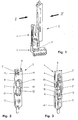
- a fitting arrangement 1 comprises a fitting part in the form of a tilting bar 2, which is known per se Way to mount on the lower corner corner area a window sash is determined. With the appropriate switch position the fitting arrangement 1 is supported by the rocker bolt, 2 on the bottom of a bearing pan 3 of a frame side Tilt lock bearing 4 and then forms together with the bearing pan 3 a tilt joint for the from the closed to the tilt opening position or vice versa to be transferred window sash.
- the rocker bar 2 has an undercut on its underside Longitudinal recess 5. As a result of the undercut of the Longitudinal recess 5 are formed on this along holding projections 6. Further, strip-like holding projections 7 run on the outside of the tilting bar 2. Breakthroughs 8, 9, 10, 11, 12 enforce the rocker bar 2, the openings 11, 12 in the longitudinal recess 5 open. At the top of the tilting bar 2, the openings 8, 9, 10, 11, 12 lie within a depression 13. This is adjacent to a screw hole 14 provided with a pre-assembled fastening screw 15.
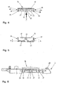
- a safety slide 16 as shown in FIGS. 4 and 5 show is molded as a plastic part and has a cover plate 17, locking elements formed thereon in the form of outer locking arms 18, 19 and an inner pair of locking arms 20 and also to the Cover plate 17 molded guide and locking elements in Form of spring tongues 21, 22.
- outer locking arms 18, 19 are between upper projections 23, 24 and lower projections 25, 26 locking receptacles 27, 28 spared.
- the locking arms of the inner locking arm pair 20 are on their mutually remote sides with locking projections 29, 30 Mistake.
- the spring tongues 21, 22 run from their approach the cover plate 17 of the locking slide 16 swung to the Edge of the cover plate 17 out. Their width over everything is shown in Fig. 5 labeled "b" and corresponds to the width of the openings 11, 12 on the rocker arm 2.
- the toggle bolt 2 with the pre-assembled on it is installed Fastening screw 15 and the pre-assembled on it Safety slide 16 delivered.
- 6 is the safety slide 16 locked with the rocker arm 2.
- Manufactured this locking connection on the outer locking arms 18, 19 of the safety slide 16, in the locking receptacles 27, 28 Engage locking projections 31, 32, which in turn on the rocker bar 2 and there on the edges of the depression 13 located mouths of the openings 8, 10 are provided.
- the Locking arms of the locking arm pair 20 are attached to the rocker arm 2 preassembled safety slide 16 inside the opening 9 of the tilting bar 2 and are supported there elastically biased from the breakthrough wall. This is in her the bottom the area facing the tilting bolt 2 with recesses 33, 34 Mistake.
- the spring tongues 21, 22 of the preassembled safety slide 16 run inside the openings 11, 12 of the tilting bar 2, without protruding into its undercut longitudinal recess 5.
- the assembly according to FIG. 6 is to be mounted on one in FIG. 7 Cut-out frame profile made of aluminum 35 of a window sash.
- the frame profile 35 has one in the circumferential direction of the fold in question Window sash circumferential fitting part groove 36, that of groove side walls 37, 38 and one of a groove opening 39 opposite groove base 40 is limited.
- the groove side walls 37, 38 form profile projections 41, 42 on the fold side of the frame profile 35 protrude from a profile surface 43.
- the profile projections 41, 42 are in with themselves Longitudinal direction of the frame profile 35 extending undercuts 44, 45 provided.
- the fitting part groove 36 has a receptacle 46 on the base of the groove for an actuating rod that can be driven in the longitudinal direction of the slot 47 on. This is profiled and has a T-shaped cross section. In the installed position it rests in with a T-cross bar 48 Wall projections 49, 50 of the groove side walls running in the longitudinal direction of the groove 37, 38.
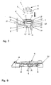
- the maximum width of the adjusting rod 47 is slightly smaller than the width of the groove opening 39. This fact allows at the fitting part assembly first the adjusting rod 47 by straight Movement perpendicular to the groove base 40 in the fitting groove 36 to insert on the frame profile 35. Then will 6, consisting of the rocker bar 2 and the pre-assembled mounting screw 15 and the also pre-assembled safety slide 16, as in FIG. 7 Shown in dashed lines, aligned with the frame profile 35. The longitudinal recess 5 of the tilting latch 2 lies with it its opening the profile projection 41 perpendicular to the bottom of the groove 40 versus. Then the assembly is made of toggle bolts 2, fastening screw 15 and safety slide 16 in the direction of the arrow drawn in Fig.
- the profile advantage 41 dips into the longitudinal recess 5 of the tilt bolt 2 a; the right of the longitudinal recess 5 Leg of the tilting bar 2, the width of which is also slight is smaller than the width of the groove opening 39, reaches the inside the fitting groove 36.
- the movement perpendicular to the groove base 40 ends as soon as the bottom of the rocker arm 2 on the profile surface 43 of the frame profile 35 or on the top the adjusting rod 47 lying in the fitting part groove 36 runs.
- the locking arms of the inner locking arm pair 20 snap of the safety slide 16 with their locking projections 29, 30 the recesses 33, 34 of the wall of the tilting bolt side Breakthrough 9 a.
- the spring tongues 21, 22 enter the space between the profile projection 41 on the frame profile 35 and the immersed in the fitting groove 36 leg of the Tilt lock 2. In this position, the spring tongues 21, 22 on the toggle 2 against leaving its engaged position the frame profile 35.
- the profile projection 41 forms a Abutment on the frame profile side for the toggle latch 2
- the spring tongues 21, 22 leave their spring elasticity under pressure a slight play in the transverse direction of the fitting part groove 36 the tilting bar 2 in the direction mentioned. Otherwise lie the spring tongues are undeformed and therefore without elastic pretension in the space between the profile projection 41 and the profile groove side leg of the tilting bar 2.
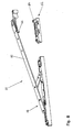
- a fitting arrangement 51 comprises a fitting part in Form of a scissor inclusion 52, which with an opening scissors 53 cooperates.
- the fitting arrangement is 51 for connecting a rotating and tilting wing a window with the associated frame.
- the opening scissors are used to open the window sash 53 in the closed state on the wing spar in question established.
- an inclusion pin 54 of the scissor inclusion 52 into a position on the wing spar in question procedure when taking it on the frame side one on one Scissor arm 55 provided abutment 56 is arranged.
- the scissor inclusion 52 and with it the inclusion pin 54 is coupled to an actuating rod and can be moved with it.
- FIG. 9 shows the scissors containment 52 with the pre-assembled fastening screw 15 as well as the preassembled and locked in its first locking position Safety slide 16, i.e. at in release position spring tongues 21, 22.
- Fig. 10 is a fitting arrangement in the form of a corner drive 61.
- This includes a fitting part in the form of a Corner bracket 62, to be attached to a corner of a window sash is.
- Coupling pieces are slidably guided on the corner bracket 62 63, 64, which are connected to one another via conventional flexible steel strips are connected and in turn on fastening screws 65, 66 can be connected to associated adjusting rod sections, those relating to the design of the actuating rod 47 according to FIG. 7 correspond.
- the corner bracket 62 consists of two perpendicular to each other Corner angle legs 67, 68. Runs on the inside an undercut longitudinal recess 69, the opening is limited on the one hand by a holding projection 70. Another Holding projection 71 runs on the opposite outside the corner angle leg 67, 68. At the holding projection 70 opposite side, the longitudinal recess 69 of a Recess side wall 72 limited. In the longitudinal recess 69 open openings 73, 74 of the corner angle legs 67, 68. The Opening 74 is concealed in FIG. 10. In the crown area the corner bracket 62 is provided with a recess 75, which has a square outer contour. The recess side wall 72 is shown in FIG.
- the corner bracket 62 or the corner deflection 61 with the attached preassembled safety slide 79 delivered to the installation site.
- FIG. 14 shows Frame profile 90 on the fold side a running in the circumferential direction of the fold Fitting part groove 91 with groove side walls 92, 93 of a groove opening 94 and a groove base 95. From a profile surface 96 are the groove side walls 92, 93 with profile projections 97, 98 in front. The profile projection 97 is on the inside of the fitting groove 91 facing side with an undercut 99 and provided with an undercut 100 on its outside.
- the profile projection 98 has on its inside an undercut 101.
- the form-fit connections also ensure the form-fit connections between the spring tongues 82, 83 and the profile projection 97 for fixing the corner deflection 61 perpendicular to the groove base 95. Due to their spring elasticity, the spring tongues leave 82, 83 an elastic play of the corner deflection 61 in the transverse direction the fitting part groove 91 too.
- This movement game can For example, be useful if the corner angle 62 guided coupling pieces 63, 64 via the fastening screws 65, 66 with the associated control rod sections connect and thereby manufacturing and / or assembly tolerances are to be balanced.
- An actuating rod section that is in the installed position 14 lies outside of the representation level of FIG indicated in dashed lines in this figure.
- the safety slide 79 is also flush in the final assembly position on the assigned fitting part, in the case of the safety slide 79 arranged at the corner bracket 62. stabilized the position of the locking slide 79 is thereby due to the positive connection between the corner bracket 78 and the into this plunging corner projection 89 on the safety slide 79 as well as by the precise fitting of the top plate 86 of the safety slide 79 in the recess 75 at the apex corner angle 62.
Landscapes
- Engineering & Computer Science (AREA)
- Mechanical Engineering (AREA)
- Wing Frames And Configurations (AREA)
- Details Of Indoor Wiring (AREA)
- Cable Accessories (AREA)
- Snaps, Bayonet Connections, Set Pins, And Snap Rings (AREA)
Abstract
Description
- Fig. 1
- eine Beschlaganordnung umfassend ein Beschlagteil in Form eines an einem Fensterflügel zu montierenden Kippriegels sowie ein zugehöriges blendrahmenseitiges Kippriegellager,
- Fig. 2
- den Kippriegel nach Fig. 1 in der perspektivischen Ansicht in Richtung des Pfeils II in Fig. 1,
- Fig. 3
- den Kippriegel nach den Fign. 1 und 2 in der perspektivischen Ansicht in Richtung des Pfeils III in Fig. 1,
- Fig. 4
- eine Seitenansicht eines Sicherungsschiebers zur Verwendung an dem Kippriegel nach den Fign. 1 bis 3,
- Fig. 5
- den Sicherungsschieber nach Fig. 4 in der Ansicht in Richtung des Pfeils V in Fig. 4,
- Fig. 6
- den Sicherungsschieber nach den Fign. 4 und 5 vormontiert an dem Kippriegel nach den Fign. 1 bis 3,
- Fig. 7
- den Kippriegel nach den Fign. 1 bis 3 mit dem Sicherungsschieber nach den Fign. 4 und 5 in Einbaulage an einem Rahmenprofil des betreffenden Fensterflügels,
- Fig. 8
- eine Beschlaganordnung umfassend eine Ausstellschere für einen Dreh-Kipp-Flügel eines Fensters sowie ein Beschlagteil in Form eines flügelseitigen Schereneinschlusses,
- Fig. 9
- den Schereneinschluss nach Fig. 8 mit dem daran vormontierten Sicherungsschieber nach den Fign. 4 und 5,
- Fig. 10
- eine als Eckumlenkung für einen Fensterflügel ausgebildete Beschlaganordnung umfassend ein Beschlagteil in Form eines Eckwinkels,
- Fig. 11
- den Eckwinkel nach Fig. 10 in der Ansicht in Richtung des Pfeils XI in Fig. 10 mit einem zugehörigen Sicherungsschieber,
- Fig. 12
- den Sicherungsschieber nach Fig. 11 in der Ansicht in Richtung des Pfeils XII in Fig. 11,
- Fig. 13
- den Sicherungsschieber nach den Fign. 11 und 12 in der Ansicht in Richtung des Pfeils XIII in Fig. 12 und
- Fig. 14
- den Eckwinkel nach den Fign. 10 und 11 mit dem Sicherungsschieber nach den Fign. 11 bis 13 in Einbaulage an einem Rahmenprofil des betreffenden Fensterflügels mit der Darstellungsebene XIV in Fig. 10.
Claims (15)
- Beschlaganordnung an einem Rahmenprofil (35, 90) eines Fensters, einer Tür oder dergleichen, wobei das Rahmenprofil (35, 90) wenigstens einen an ihm überstehenden und mit zumindest einem Hinterschnitt (44, 45; 100, 101) versehenen Profilvorsprung (41, 42; 97, 98) aufweist und wobei wenigstens ein Beschlagteil (2, 52, 62) in Einbaulage mit zumindest einem Haltevorsprung (6, 7; 70, 71) in den Hinterschnitt (44, 45; 100, 101) des Profilvorsprungs (41, 42; 97, 98) eingreift und das in der Eingriffsstellung befindliche Beschlagteil (2, 52, 62) mittels wenigstens einer Beschlagteilsicherung an der dem Hinterschnitt (44, 100) gegenüberliegenden Seite zumindest eines Profilvorsprungs (41, 97) gegen Verlassen der Eingriffsstellung an einem rahmenprofilseitigen Widerlager (41, 97) quer zu der Richtung des Überstandes des Profilvorsprungs (41, 97) abgestützt ist, dadurch gekennzeichnet, dass die Beschlagteilsicherung als Sicherungsschieber (16, 79) ausgebildet ist, der wenigstens ein Führungselement (21, 22; 82, 83, 87, 88), wenigstens ein Sicherungselement (21, 22; 82, 83) und wenigstens ein Rastelement (20; 82, 83) aufweist, der mittels des Führungselementes (21, 22; 82, 83, 87, 88) an dem Beschlagteil (2, 52, 62) in Richtung des Überstandes des zugeordneten Profilvorsprungs (41, 97) verschiebbar geführt und der in der genannten Richtung aus einer Freigabestellung in eine Sicherungsstellung verschiebbar ist, wobei der in der Freigabestellung befindliche Sicherungsschieber (16, 79) mit dem Sicherungselement (21, 22; 82, 83) das Beschlagteil (2, 52, 62) zum Verlassen der Eingriffsstellung freigibt und wobei der in der Sicherungsstellung befindliche Sicherungsschieber (16, 79) das Beschlagteil (2, 52, 62) mittels des Sicherungselementes (21, 22; 82, 83) an dem rahmenprofilseitigen Widerlager (41, 97) gegen Verlassen der Eingriffsstellung abstützt und mittels des Rastelements (20; 82, 83) gegen Verschieben in die Freigabestellung verrastet ist.
- Beschlaganordnung nach Anspruch 1, dadurch gekennzeichnet, dass der in der Sicherungsstellung befindliche Sicherungsschieber (16) mittels des Rastelements (20) an dem Beschlagteil (2, 52) gegen Verschieben in die Freigabestellung verrastet ist.
- Beschlaganordnung nach Anspruch 1 oder 2, dadurch gekennzeichnet, dass der Sicherungsschieber (16, 79) in einer Freigabestellung mittels wenigstens eines Rastelementes (18, 19; 87) an dem Beschlagteil (2, 52, 62) lösbar verrastet ist.
- Beschlaganordnung nach einem der vorhergehenden Ansprüche, dadurch gekennzeichnet, dass wenigstens ein Führungselement (82, 83) gleichzeitig als Rastelement und/oder als Sicherungselement ausgebildet ist.
- Beschlaganordnung nach einem der vorhergehenden Ansprüche, dadurch gekennzeichnet, dass wenigstens ein Sicherungselement (82, 83) gleichzeitig als Rastelement ausgebildet ist.
- Beschlaganordnung nach einem der vorhergehenden Ansprüche, dadurch gekennzeichnet, dass wenigstens ein Sicherungselement (21, 22; 82, 83) in Richtung der Abstützung an dem rahmenprofilseitigen Widerlager (41, 97) federelastisch ausgebildet ist.
- Beschlaganordnung nach einem der vorhergehenden Ansprüche, dadurch gekennzeichnet, dass wenigstens ein federelastisches Sicherungselement (21, 22; 82, 83) als Federzunge ausgebildet ist.
- Beschlaganordnung nach einem der vorhergehenden Ansprüche, dadurch gekennzeichnet, dass das Sicherungselement (82, 83) und der zugeordnete Profilvorsprung (97) an ihren einander zugewandten Seiten einerseits wenigstens einen Hinterschnitt (99) und andererseits wenigstens einen Rastvorsprung (84, 85) aufweisen und dass das in der Sicherungsstellung befindliche Sicherungselement (82, 83) und der zugeordnete Profilvorsprung (97) an dem Hinterschnitt (99) und dem Rastvorsprung (84, 85) miteinander verrastet sind.
- Beschlaganordnung nach einem der vorhergehenden Ansprüche, wobei der Profilvorsprung (41, 42) von einer Nutseitenwand (37, 38) einer Beschlagteilnut (36) des Rahmenprofils (35) gebildet ist, dadurch gekennzeichnet, dass der in der Sicherungsstellung befindliche Sicherungsschieber (16) das Beschlagteil (2, 52) in Nutlängsrichtung beweglich an dem rahmenprofilseitigen Widerlager (41), vorzugsweise an der Nutseitenwand (37), gegen Verlassen der Eingriffsstellung abstützt.
- Beschlaganordnung nach Anspruch 9, dadurch gekennzeichnet, dass eine in Nutlängsrichtung angetrieben bewegbare Stellstange (47) in der Beschlagteilnut (36) unterhalb des Beschlagteils (2, 52) angeordnet und mit dem Beschlagteil (2, 52) verbindbar ist und dass der in der Sicherungsstellung befindliche Sicherungsschieber (16) das mit der Stellstange (47) verbundene Beschlagteil (2, 52) in Nutlängsrichtung beweglich an dem rahmenprofilseitigen Widerlager (41), vorzugsweise an der Nutseitenwand (37), gegen Verlassen der Eingriffsstellung abstützt.
- Beschlaganordnung nach einem der vorhergehenden Ansprüche, dadurch gekennzeichnet, dass die Öffnungsweite der Beschlagteilnut (36) wenigstens ebenso groß ist wie die Breite der Stellstange (47).
- Beschlaganordnung nach einem der vorhergehenden Ansprüche, dadurch gekennzeichnet, dass das mit der Stellstange (47) verbundene Beschlagteil (2, 52) über die Stellstange (47) gegen Verlassen der Eingriffsstellung an dem Rahmenprofil (35) abgestützt ist.
- Beschlaganordnung nach einem der vorhergehenden Ansprüche in Form einer Eckumlenkung (61), wobei das Beschlagteil (62) von einem Eckwinkel der Eckumlenkung (61) und der Profilvorsprung (97, 98) von einer Nutseitenwand (92, 93) einer Beschlagteilnut (91) in einem Eckbereich des Rahmenprofils (90) gebildet ist, dadurch gekennzeichnet, dass der Sicherungsschieber (79) unter Ausbildung zweier Schieberschenkel (80, 81) abgewinkelt ist, wobei jeder der Schieberschenkel (80, 81) einen der Eckwinkelschenkel (67, 68) zumindest teilweise überdeckt und wenigstens ein Sicherungselement (82, 83) aufweist, mittels dessen der betreffende Eckwinkelschenkel (67, 68) bei in der Sicherungsstellung befindlichem Sicherungsschieber (79) an dem rahmenprofilseitigen Widerlager (97), vorzugsweise an der Nutseitenwand (92), gegen Verlassen der Eingriffsstellung abgestützt ist.
- Beschlaganordnung nach einem der vorhergehenden Ansprüche, dadurch gekennzeichnet, dass der in der Sicherungsstellung befindliche Sicherungsschieber (16, 79) an der Sichtseite des Beschlagteils (2, 52, 62) mit diesem im Wesentlichen flächenbündig angeordnet ist.
- Beschlaganordnung nach einem der vorhergehenden Ansprüche, dadurch gekennzeichnet, dass das freie Ende des Sicherungselementes und/oder das freie Ende des diesem zugeordneten Profilvorsprungs mit einer keilartigen Schrägfläche versehen ist, und dass die beiderseitigen freien Enden bei der Verschiebung des Sicherungsschiebers aus der Freigabe- in die Sicherungsstellung aneinander entlang gleiten unter Verschieben des Beschlagteils aus einer Position, in welcher sein Haltevorsprung außerhalb des zugeordneten Hintergriffs an dem Profilvorsprung angeordnet ist, in die Eingriffsstellung an dem Profilvorsprung.
Priority Applications (3)
| Application Number | Priority Date | Filing Date | Title |
|---|---|---|---|
| DE50113120T DE50113120D1 (de) | 2001-04-28 | 2001-04-28 | Beschlaganordnung mit Beschlagteilsicherung |
| EP01110550A EP1253272B1 (de) | 2001-04-28 | 2001-04-28 | Beschlaganordnung mit Beschlagteilsicherung |
| AT01110550T ATE375428T1 (de) | 2001-04-28 | 2001-04-28 | Beschlaganordnung mit beschlagteilsicherung |
Applications Claiming Priority (1)
| Application Number | Priority Date | Filing Date | Title |
|---|---|---|---|
| EP01110550A EP1253272B1 (de) | 2001-04-28 | 2001-04-28 | Beschlaganordnung mit Beschlagteilsicherung |
Publications (2)
| Publication Number | Publication Date |
|---|---|
| EP1253272A1 true EP1253272A1 (de) | 2002-10-30 |
| EP1253272B1 EP1253272B1 (de) | 2007-10-10 |
Family
ID=8177278
Family Applications (1)
| Application Number | Title | Priority Date | Filing Date |
|---|---|---|---|
| EP01110550A Expired - Lifetime EP1253272B1 (de) | 2001-04-28 | 2001-04-28 | Beschlaganordnung mit Beschlagteilsicherung |
Country Status (3)
| Country | Link |
|---|---|
| EP (1) | EP1253272B1 (de) |
| AT (1) | ATE375428T1 (de) |
| DE (1) | DE50113120D1 (de) |
Cited By (3)
| Publication number | Priority date | Publication date | Assignee | Title |
|---|---|---|---|---|
| CN110130729A (zh) * | 2019-06-19 | 2019-08-16 | 深圳好博窗控技术有限公司 | 一种安装结构 |
| CN110130726A (zh) * | 2019-06-19 | 2019-08-16 | 深圳好博窗控技术有限公司 | 一种安装结构 |
| CN114808116A (zh) * | 2022-05-20 | 2022-07-29 | 中国电子科技集团公司第十一研究所 | 一种应用于水平液相外延技术的石墨舟 |
Families Citing this family (1)
| Publication number | Priority date | Publication date | Assignee | Title |
|---|---|---|---|---|
| CN220769191U (zh) * | 2023-07-19 | 2024-04-12 | 广东精诺五金实业有限公司 | 一种用于家具的铰链组件 |
Citations (2)
| Publication number | Priority date | Publication date | Assignee | Title |
|---|---|---|---|---|
| DE2248217A1 (de) | 1972-10-02 | 1974-04-11 | Kalinna Erwin Fa | Beschlagsbefestigung |
| EP0353485A2 (de) * | 1988-07-13 | 1990-02-07 | Elleci S.R.L. | Scharnier zur schnellen Befestigung an Profilelementen von Flügelrahmen oder ähnlichem |
-
2001
- 2001-04-28 EP EP01110550A patent/EP1253272B1/de not_active Expired - Lifetime
- 2001-04-28 AT AT01110550T patent/ATE375428T1/de active
- 2001-04-28 DE DE50113120T patent/DE50113120D1/de not_active Expired - Lifetime
Patent Citations (2)
| Publication number | Priority date | Publication date | Assignee | Title |
|---|---|---|---|---|
| DE2248217A1 (de) | 1972-10-02 | 1974-04-11 | Kalinna Erwin Fa | Beschlagsbefestigung |
| EP0353485A2 (de) * | 1988-07-13 | 1990-02-07 | Elleci S.R.L. | Scharnier zur schnellen Befestigung an Profilelementen von Flügelrahmen oder ähnlichem |
Cited By (4)
| Publication number | Priority date | Publication date | Assignee | Title |
|---|---|---|---|---|
| CN110130729A (zh) * | 2019-06-19 | 2019-08-16 | 深圳好博窗控技术有限公司 | 一种安装结构 |
| CN110130726A (zh) * | 2019-06-19 | 2019-08-16 | 深圳好博窗控技术有限公司 | 一种安装结构 |
| CN114808116A (zh) * | 2022-05-20 | 2022-07-29 | 中国电子科技集团公司第十一研究所 | 一种应用于水平液相外延技术的石墨舟 |
| CN114808116B (zh) * | 2022-05-20 | 2023-08-15 | 中国电子科技集团公司第十一研究所 | 一种应用于水平液相外延技术的石墨舟 |
Also Published As
| Publication number | Publication date |
|---|---|
| ATE375428T1 (de) | 2007-10-15 |
| EP1253272B1 (de) | 2007-10-10 |
| DE50113120D1 (de) | 2007-11-22 |
Similar Documents
| Publication | Publication Date | Title |
|---|---|---|
| DE69803296T2 (de) | Halterung für eine abschirmvorrichtung | |
| CH624729A5 (de) | ||
| DE3738300A1 (de) | Fenster, tuer od. dgl. bei dem bzw. der zumindest der fluegelrahmen aus metall- oder kunststoffprofilen zusammengesetzt ist | |
| DE4123213A1 (de) | Schublade mit metallischen zargen | |
| EP2055888B1 (de) | Tür mit Dichtung und Türdichtung hierfür | |
| DE202022002815U1 (de) | Verbesserte Inspektionsklappe | |
| DD292294A5 (de) | Fuehrungsanordnung | |
| EP0718456A1 (de) | Fenster, Tür, od. ähnlicher Öffnungsverschluss | |
| EP2088337A2 (de) | Profil und Profilsystem | |
| EP0843064B1 (de) | Beschlag für ein Fenster | |
| EP1067265B1 (de) | Beschlagsystem für Drehkippfenster oder Drehkipptüren | |
| EP1253272B1 (de) | Beschlaganordnung mit Beschlagteilsicherung | |
| DE69005538T2 (de) | Einstellbares Verglasungssystem. | |
| EP0459987B1 (de) | Gerätegehäuse mit zwei gehäuseschalen | |
| EP1253270B1 (de) | Rahmenprofil für Fenster, Tür oder dergleichen | |
| DE602004004982T2 (de) | Eckumlenkung für Türen und Fenster | |
| DE69205091T2 (de) | Aushebevorbeugungsvorrichtung für Schiebeflügel, insbesondere einer Tür, eines Fensters oder ähnlichem. | |
| DE102007030750B4 (de) | Verbindung | |
| EP1067264B1 (de) | Treibstangenbeschlag-System und Stulpeneinsatzkörper hierfür | |
| EP4146888A1 (de) | Scharnierbaugruppe mit gemeinsamer betätigung | |
| DE19734647B4 (de) | Beschlagteil an einem Flügel oder einem festen Rahmen eines Fensters, einer Tür od. dgl. | |
| DE29824769U1 (de) | Schieberstange | |
| DE102020112148B3 (de) | Scharnierverschluss | |
| DE19857384C2 (de) | Befestigungsmittel zum Verbinden eines Flügelrahmens mit einem Blendrahmen zu einem nicht öffenbaren Fenster | |
| DE3426439A1 (de) | Scharnier fuer schrankgestelle der nachrichtentechnik |
Legal Events
| Date | Code | Title | Description |
|---|---|---|---|
| PUAI | Public reference made under article 153(3) epc to a published international application that has entered the european phase |
Free format text: ORIGINAL CODE: 0009012 |
|
| 17P | Request for examination filed |
Effective date: 20010807 |
|
| AK | Designated contracting states |
Kind code of ref document: A1 Designated state(s): AT BE CH CY DE DK ES FI FR GB GR IE IT LI LU MC NL PT SE TR |
|
| AX | Request for extension of the european patent |
Free format text: AL;LT;LV;MK;RO;SI |
|
| AKX | Designation fees paid |
Designated state(s): AT BE CH DE FR IT LI |
|
| GRAP | Despatch of communication of intention to grant a patent |
Free format text: ORIGINAL CODE: EPIDOSNIGR1 |
|
| GRAS | Grant fee paid |
Free format text: ORIGINAL CODE: EPIDOSNIGR3 |
|
| GRAA | (expected) grant |
Free format text: ORIGINAL CODE: 0009210 |
|
| AK | Designated contracting states |
Kind code of ref document: B1 Designated state(s): AT BE CH DE FR IT LI |
|
| REG | Reference to a national code |
Ref country code: CH Ref legal event code: EP |
|
| REF | Corresponds to: |
Ref document number: 50113120 Country of ref document: DE Date of ref document: 20071122 Kind code of ref document: P |
|
| ET | Fr: translation filed | ||
| PLBE | No opposition filed within time limit |
Free format text: ORIGINAL CODE: 0009261 |
|
| STAA | Information on the status of an ep patent application or granted ep patent |
Free format text: STATUS: NO OPPOSITION FILED WITHIN TIME LIMIT |
|
| 26N | No opposition filed |
Effective date: 20080711 |
|
| REG | Reference to a national code |
Ref country code: FR Ref legal event code: PLFP Year of fee payment: 15 |
|
| PGFP | Annual fee paid to national office [announced via postgrant information from national office to epo] |
Ref country code: CH Payment date: 20150422 Year of fee payment: 15 |
|
| PGFP | Annual fee paid to national office [announced via postgrant information from national office to epo] |
Ref country code: IT Payment date: 20150430 Year of fee payment: 15 Ref country code: FR Payment date: 20150429 Year of fee payment: 15 Ref country code: BE Payment date: 20150429 Year of fee payment: 15 Ref country code: AT Payment date: 20150424 Year of fee payment: 15 |
|
| PG25 | Lapsed in a contracting state [announced via postgrant information from national office to epo] |
Ref country code: BE Free format text: LAPSE BECAUSE OF NON-PAYMENT OF DUE FEES Effective date: 20160430 |
|
| REG | Reference to a national code |
Ref country code: CH Ref legal event code: PL |
|
| REG | Reference to a national code |
Ref country code: AT Ref legal event code: MM01 Ref document number: 375428 Country of ref document: AT Kind code of ref document: T Effective date: 20160428 |
|
| REG | Reference to a national code |
Ref country code: FR Ref legal event code: ST Effective date: 20161230 |
|
| PG25 | Lapsed in a contracting state [announced via postgrant information from national office to epo] |
Ref country code: LI Free format text: LAPSE BECAUSE OF NON-PAYMENT OF DUE FEES Effective date: 20160430 Ref country code: CH Free format text: LAPSE BECAUSE OF NON-PAYMENT OF DUE FEES Effective date: 20160430 Ref country code: FR Free format text: LAPSE BECAUSE OF NON-PAYMENT OF DUE FEES Effective date: 20160502 |
|
| PG25 | Lapsed in a contracting state [announced via postgrant information from national office to epo] |
Ref country code: AT Free format text: LAPSE BECAUSE OF NON-PAYMENT OF DUE FEES Effective date: 20160428 Ref country code: IT Free format text: LAPSE BECAUSE OF NON-PAYMENT OF DUE FEES Effective date: 20160428 |
|
| PGFP | Annual fee paid to national office [announced via postgrant information from national office to epo] |
Ref country code: DE Payment date: 20190427 Year of fee payment: 19 |
|
| REG | Reference to a national code |
Ref country code: DE Ref legal event code: R119 Ref document number: 50113120 Country of ref document: DE |
|
| PG25 | Lapsed in a contracting state [announced via postgrant information from national office to epo] |
Ref country code: DE Free format text: LAPSE BECAUSE OF NON-PAYMENT OF DUE FEES Effective date: 20201103 |