EP1252960A1 - Oxycoupage de brames froides ou chaudes sans cordons - Google Patents
Oxycoupage de brames froides ou chaudes sans cordons Download PDFInfo
- Publication number
- EP1252960A1 EP1252960A1 EP01201540A EP01201540A EP1252960A1 EP 1252960 A1 EP1252960 A1 EP 1252960A1 EP 01201540 A EP01201540 A EP 01201540A EP 01201540 A EP01201540 A EP 01201540A EP 1252960 A1 EP1252960 A1 EP 1252960A1
- Authority
- EP
- European Patent Office
- Prior art keywords
- slab
- cutting
- flame cutting
- flame
- cut
- Prior art date
- Legal status (The legal status is an assumption and is not a legal conclusion. Google has not performed a legal analysis and makes no representation as to the accuracy of the status listed.)
- Granted
Links
Images



Classifications
-
- B—PERFORMING OPERATIONS; TRANSPORTING
- B23—MACHINE TOOLS; METAL-WORKING NOT OTHERWISE PROVIDED FOR
- B23K—SOLDERING OR UNSOLDERING; WELDING; CLADDING OR PLATING BY SOLDERING OR WELDING; CUTTING BY APPLYING HEAT LOCALLY, e.g. FLAME CUTTING; WORKING BY LASER BEAM
- B23K7/00—Cutting, scarfing, or desurfacing by applying flames
- B23K7/002—Machines, apparatus or equipment for cutting plane workpieces, e.g. plates
-
- B—PERFORMING OPERATIONS; TRANSPORTING
- B23—MACHINE TOOLS; METAL-WORKING NOT OTHERWISE PROVIDED FOR
- B23K—SOLDERING OR UNSOLDERING; WELDING; CLADDING OR PLATING BY SOLDERING OR WELDING; CUTTING BY APPLYING HEAT LOCALLY, e.g. FLAME CUTTING; WORKING BY LASER BEAM
- B23K2101/00—Articles made by soldering, welding or cutting
- B23K2101/18—Sheet panels
Definitions
- the invention relates to a flame cutting process. a parallelepiped slab using one or more flame cutting torches and a device for setting it up artwork.
- the object of the invention is to provide a method flame cutting of slabs and a device for its implementation work that does not have such drawbacks.
- this object is achieved by a process of flame cutting a slab using at least one flame cutting torch in a work station, comprising the step of making a relative movement between the slab and at least one flame cutting torch, the slab being in a cutting position, in which the slab is arranged so that the main plane of the slab forms an angle of -10 ° to -20 ° by contribution to the vertical plane.
- each workstation In each workstation the slab in a cutting position, in which the slab is arranged so that the main plane of the slab forms an angle of -10 ° to -20 ° by contribution to the plane vertical, each of the workstations being used for loading, flame cutting and unloading a slab to be cut, the oxycutting being done alternately on one of the two workstations.
- one of the workstations can be used to load the slab and the other station can be used to unload the cut slab, and an additional workstation can be provided in line between the two so-called workstations to run flame cutting of the slab in its position from -10 ° to -20 ° from vertical, the slab to be cut loaded on the loading work being moved from the work station to loading to that additional workstation and then on the unloading workstation to unload the cut slab, the slab being subjected to the operation oxygen cutting during its passage in the work station additional.
- the slab can be split or cut for oxygen cutting by the relative movement carried out between the slab and the flame cutting torch.
- Slabs can be loaded continuously to be transported in front of the flame cutting torch and then be split or cut according to the direction of the relative movement between each slab and the torch flame cutting.
- the device for setting implementing the method comprises at least one blowtorch flame cutting to flame cutting a slab by making a relative movement between the slab and the torch of flame cutting, and a means for holding a slab to be cut from so that the main plane of the slab forms an angle of -10 ° to -20 ° relative to a vertical plane.
- Said means of holding a slab can include rollers placed in pairs at right angles receive and hold the slab to be cut on edge from the angle from -10 ° to -20 ° and to form an oblique support plane.
- At least one pair of mobile rules to in unison along and in rider on said support plane oblique of the means for holding a slab may be provided for each receive one of said at least one blowtorch oxygen cutting and its associated deburring device and place said a flame cutting torch and its means deburring associated with a desired cutting location along the longitudinal extension of a slab held by the means to hold a slab to cut it at said place of desired cut.
- a second way to hold a slab so the main plane of the slab forms the same angle from -10 ° to -20 ° relative to the vertical plane said second means for holding a slab also comprising rollers placed in pairs in square to receive and hold the slab to be cut on edge from the angle of -10 ° to -20 ° and to form a second plane oblique support, said at least one pair of rules movable in unison along and in jumper on said oblique support plane of the means for holding a slab and each receive one of said at least one blowtorch oxycutting and its associated deburring device, for place said a flame cutting torch and its device deburring associated with the desired cutting location along the longitudinal extension of a slab held by said means for holding a slab for cutting it in said place desired, can be moved to place it in jumper on said second oblique support plane for flame cutting of a slab loaded on said second means to hold a slab at the desired cutting location.
- a workstation can be placed online between said means for holding a slab and said second means for holding a slab, said work station comprising a series of rollers placed in pairs in angle to receive a slab on edge at an angle of -10 ° to -20 ° from the vertical plane on a third oblique support plane formed by said series of rollers placed in pairs at right angles, said pair of rules being movable in unison and in a jumper on said third support plane oblique, and said rolls of said pairs of rollers receiving the slab on edge being motorized for moving the slab from said means to hold a slab on said workstation for the flame cutting of the slab and to move the cut slab from said workstation to said second means for holding a slab to discharge the slab cut.
- Said means for holding a slab may be tilted with their oblique support plane in a horizontal position to load a slab or unload a slab cut, respectively.
- an oxygen cutting device for slabs using at least one flame cutting torch can also include a feeding area, an area flame cutting provided with said at least one torch flame cutting facing a deburring device associated, the slab being in said flame cutting area with its main plane in horizontal position between said at least one flame cutting torch and its device associated deburring, and an unloading area for slabs, means being provided for circulating the slab from the feed area to the flame cutting area and then to the unloading area, and the torch oxygen cutting that can be moved on a line perpendicular to the longitudinal extension of the slab from a longitudinal edge thereof to the edge opposite longitudinal for cutting slabs subject to the flame cutting operation and can be stopped at any point on said perpendicular line of so as to allow the slitting of slabs subjected to the flame cutting procedure and submitted during the operation of oxygen cutting to a movement towards the extension longitudinal of the slab.
- the feeding area and / or the unloading may include an adjustable lifting table so that its support plane is at the level of the flame cutting area.
- the flame cutting area can consist of a sufficient number of axle support rollers perpendicular to the direction of movement of the slabs of the feeding area towards the unloading area forming a support plane, said at least one flame cutting torch and its associated deburring device being arranged in the space between two neighboring support rollers and share and on the other side of the support plane formed by the rollers support.
- the means provided for circulating the slabs can include slab pushers in the feeding area and motorized support rollers.
- the device may include rolls of additional motorized support on either side of the flame cutting area to form a train of rollers of transfer and feeding area and unloading can be arranged laterally of said train transfer, and slab pushers to discharge the slabs cut or split can be provided in the unloading area.
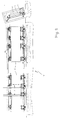
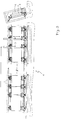
- Figures 1 to 3 show a mode of production of a device 1 for flame cutting 2 with two work stations, using at least one blowtorch flame cutting 3 according to the invention, in front view and view side, in different states of use, i.e. slab-free rest, in service for flame cutting a slab on the left post, the right post is already loaded another slab 2 to be cut, and in service for the flame cutting of slab 2 on the right post, a slab 2, having just been cut on the left post, being ready to be removed.
- states of use i.e. slab-free rest
- Each workstation includes a frame support 4 tiltable between a horizontal position (not shown) and a tilted position at an angle to it vertically from -20 ° to -10 °, preferably -15 °, as well as shown in Figures 1 to 3.
- each workstations are each mobile along the extension longitudinal of the associated support frame 4 using suitable means known to those skilled in the art. This allows place each pair of rollers 5, 6 at the place suitable where they do not interfere with the operation of the torch flame cutting 3 to cut the slab 2 resting on the lower rollers 6 on edge and on rollers 5 forming the oblique support plane.
- the flame cutting torch 3 and its device associated deburring are located opposite each other and on either side of the rollers 5; in service the slab 2 to cut is between them.
- the flame cutting torch 2 and its device associated deburring are movable along their rule 7, 8 in the direction of the double arrow 10. In service on a slab to be cut 2, the torch cuts the slab 2, transversely to its longitudinal extension; slab 2 is debited.
- the slab cutting operation takes place as follows: One of the support frames 4 is folded down in the horizontal position. A slab 2 to be cut is loaded at using appropriate handling means, i.e. of lifting or pushing on the rollers 5 until touching the rollers 6.
- the support frame 4 is tilted in the position cutting angle from -20 ° to -10 ° to the vertical, preferably 15 °.
- the flame cutting torch 2 is moved along the longitudinal extension of frame 4 at the location of slab 2 where it is to be cut. If the flame cutting torch 2 and its deburring device associated must then be at the place of space free between two pairs of rollers 5, 6.
- the device described only allows it is difficult to split a slab 2 by flame cutting. AT this can be done between the two workstations which have just been described and in line with these a third workstation with support frame 4 adjustable in a working position between -20 ° and -10 ° relative to the vertical, but not necessarily tiltable horizontal position, but for the rest identical to both other positions described above.
- Such a device is shown schematically in Figure 4.
- the rules 7, 8 with the flame cutting torch 3 and the system associated deburring are in principle movable on the frame support 4 of the third workstation, while being able be moved to the other two positions for work individuals possible.
- the lower rollers 6 or part thereof fewer of these rollers can be motorized to move slab 2, after being loaded on the station operating for loading, to the third station work for the flame cutting of the slab, and move the slab 2 then to the next station operating to unload slab 2 cut.
- the support frames 4 of extreme positions can be folded into position horizontal for loading a slab 2 on the rollers 5 or the unloading of a slab 2 cut from rollers 5.
- the number of pairs of rules 7, 8 will depend on the number of slab pieces to be made from a slab 2 to split. Before slitting a slab, it is also possible to first charge the slab 2.
- the mode of embodiment shown in the figure therefore allows either debit, either resell, or also debit and resell continuous slabs.
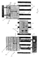
- FIG. 5 An additional embodiment of a slab flame cutting device is shown in Figures 5 and 6.
- the flame cutting device comprises a slab loading area 12, work area 13 where the flame cutting of the slabs 2 is carried out using a flame cutting torch 15 which is facing a deburring 16, and a slab unloading area 14 2 cut.
- slab 2 passes in horizontal position between the flame cutting torch 15 and the deburring device 16 on support rollers 17.
- a table can be provided lift 18 or 19 adjustable so that the plane of the table 18 or 19 or the upper plane of a slab 2 or a pile of slabs lies in the plane formed by the rollers 17.
- a hydraulic or mechanical pusher means 20 is provided to push slab 2 from table 18 or slab 2 top of a stack of slabs on the lift table 18 in and through work area 13.
- some of the rollers 17 can be motorized to transport the slab in and out of area 13 working in area 14 unloading or other pusher means or handling, not shown, removes slab or pile of slabs.
- the lifting table 19 is adjustable in height from so that its plane or the upper surface of a slab 2 on table 19 is in the same plane as the plane formed by the support rollers 17 to receive the slab 2 cut, i.e. debited or resold.
- Figure 6 is a schematic representation of a variant of the slab flame-cutting device according to Figure 6.
- the train of support rollers 17 is extended on both sides of work area 13 in loading areas 12 and 14 and lifting tables 18, 19 are placed next to the support rollers 17 in said loading 12 and unloading zones 14.
- the level of said tables or the upper surface of the slabs deposited on them are in the same plane as the support plane formed by the support rollers 17.
- the split slab 2 is pushed by a means pusher 10 of table 18 of loading area 12, in direction of the arrow 23 on the rollers 17, which transport to and through work area 12 where the slab 2 is, for example, split into three pieces of slab of equal or different widths using torches flame cutting 15.
- the transport of slab 2 continues in direction of arrow 22 on rollers 17 in the area unloading 14 or the pieces of the split slab are pushed by the means pushing 21 towards the arrow 24 on the table 19 of the unloading area 14.
Landscapes
- Engineering & Computer Science (AREA)
- Mechanical Engineering (AREA)
- Arc Welding In General (AREA)
- Metal Rolling (AREA)
- Shearing Machines (AREA)
- Heat Treatment Of Steel (AREA)
- Internal Circuitry In Semiconductor Integrated Circuit Devices (AREA)
- Heat Treatments In General, Especially Conveying And Cooling (AREA)
- Processing Of Stones Or Stones Resemblance Materials (AREA)
- Treatment Of Fiber Materials (AREA)
- Turning (AREA)
Abstract
Description
Claims (18)
- Procédé d'oxycoupage d'une brame (2) à l'aide d'au moins un chalumeau d'oxycoupage (3) dans un poste de travail, comprenant l'étape de réaliser un mouvement relatif entre la brame (2) et le au moins un chalumeau d'oxycoupage, la brame (2) se trouvant dans une position de coupe, caractérisé en ce que dans la position de coupe la brame (2) est disposée de sorte que le plan principal de la brame forme un angle de -10° à -20° par apport au plan vertical.
- Procédé d'oxycoupage selon la revendication 1, caractérisé en ce que pour le travail continu deux postes de travail sont prévus en ligne, que dans chaque poste de travail la position de coupe la brame (2) est disposée de sorte que le plan principal de la brame forme un angle de -10° à -20° par apport au plan vertical, et que chacun des postes est utilisé pour le chargement, l'oxycoupage et le déchargement d'une brame (2) à couper, et que l'oxycoupage se fait alternativement sur l'un des deux postes de travail.
- Procédé d'oxycoupage selon la revendication 2, caractérisé en ce que l'un des postes de travail sert au chargement de la brame (2) à couper et que l'autre des postes de travail sert au déchargement de la brame (2) coupée, qu'un poste de travail supplémentaire est prévu en ligne entre les deux dits postes de travail pour exécuter l'oxycoupage de la brame (2) dans une position de coupe de -10° à -20° de la verticale, que la brame (2) à couper chargée sur le poste de travail de chargement est déplacée du poste de travail de chargement audit poste de travail supplémentaire et puis sur le poste de travail de déchargement pour y décharger la brame coupée, la brame (2) étant soumise à l'opération d'oxycoupage lors de son passage dans le poste de travail supplémentaire.
- Procédé d'oxycoupage selon une quelconque des revendications 1 à 3, caractérisé en ce que la brame (2) est refendue pendant l'oxycoupage.
- Procédé d'oxycoupage selon une quelconque des revendications 1 ou 2, caractérisé en ce que la brame (2) est débitée lors du mouvement relatif entre la brame (2) et le chalumeau d'oxycoupage (3).
- Procédé d'oxycoupage selon la revendication 3, caractérisé en ce que la brame (2) est arrêtée dans le poste de travail supplémentaire pour utiliser le mouvement relatif entre la brame (2) et le chalumeau d'oxycoupage (3) pour débiter la brame.
- Procédé d'oxycoupage selon la revendication 1, caractérisé en ce que les brames (2) sont chargées en continu pour être transportées devant le chalumeau d'oxycoupage (3) et sont alors refendues ou débitées suivant la direction du mouvement relatif entre chaque brame (2) et le chalumeau d'oxycoupage (3).
- Dispositif pour la mise en oeuvre du procédé selon une quelconque des revendications 1 à 7, comprenant au moins un chalumeau d'oxycoupage (3) pour oxycouper une brame en réalisant un mouvement relatif entre la brame et le chalumeau d'oxycoupage (3), caractérisé par un moyen (4) pour tenir une brame (2) à couper de sorte que le plan principal de la brame forme un angle de -10° à -20° par rapport à un plan vertical.
- Dispositif selon la revendication 8,
caractérisé en ce que ledit moyen (4) pour tenir une brame (2) comprend des rouleaux (5,6) placés par paires en équerre pour recevoir et tenir la brame à couper sur chant sous l'angle de -10° à -20° et pour former un plan d'appui oblique. - Dispositif selon la revendication 9,
caractérisé par au moins une paire de règles (7,8) mobiles à l'unisson le long du et en cavalier sur ledit plan d'appui oblique du moyen (4) pour tenir une brame (2) et recevant chacune un desdits au moins un chalumeau d'oxycoupage (3) et son dispositif d'ébavurage associé pour placer ledit un chalumeau d'oxycoupage (3) et son moyen d'ébavurage associé à un endroit de coupage désiré le long de l'extension longitudinale d'une brame (2) tenue par ledit moyen (4) pour tenir une brame (2) pour l'oxycouper audit endroit de coupage désiré. - Dispositif selon la revendication 9, caractérisé en ce que, pour le fonctionnement continu de l'oxycoupage de brames (2), sont prévues en ligne: un deuxième moyen (4) pour tenir une brame (2) de sorte que le plan principal de la brame (2) forme un même angle de -10° à -20° par rapport au plan vertical, ledit deuxième moyen (4) pour tenir une brame (2) comprenant également des rouleaux (5,6) placés par paires en équerre pour recevoir et tenir la brame (2) à couper sur chant sous l'angle de -10° à -20° et pour former un second plan d'appui oblique, ladite au moins une paire de règles (7,8) mobiles à l'unisson le long du et en cavalier sur ledit plan d'appui oblique du moyen (4) pour tenir une brame (2) et recevont chacun un desdits au moins un chalumeau d'oxycoupage (3) et son dispositif d'ébavurage associé, pour placer ledit un chalumeau d'oxycoupage (2) et son moyen d'ébavurage associé à l'endroit de coupage désiré le long de l'extension longitudinale d'une brame (2) tenue par ledit moyen (4) pour tenir une brame (2) pour l'oxycouper audit endroit de coupage désiré, pouvant être déplacée le long desdits plans d'appui obliques pour la placer en cavalier sur ledit second plan d'appui oblique pour l'oxycoupage d'une brame chargée sur ledit deuxième moyen (4) pour tenir une brame (2) audit endroit de coupage désiré.
- Dispositif selon la revendication 11,
caractérisé par un poste de travail placé en ligne entre ledit moyen (4) pour tenir une brame et ledit deuxième moyen (4) pour tenir une brame, ledit poste de travail comprenant une suite de rouleaux (5,6) placés par paires en équerre pour recevoir une brame (2) sur chant sous un angle de -10° à -20° par rapport au plan vertical sur un troisième plan d'appui oblique formés par ladite suite des rouleaux (5,6) placés par paires en équerre, ladite paire de règles (7,8) étant mobile à l'unisson et en cavalier sur ledit troisième plan d'appui oblique, et lesdits rouleaux (6) desdits rouleaux (5,6) recevant la brame sur chant étant motorisés pour déplacer la brame (2) dudit moyen (4) pour tenir une brame sur ledit poste de travail pour l'oxycoupage de la brame (2) et pour déplacer la brame (2) coupée dudit poste de travail sur ledit deuxième moyen (4) pour tenir une brame pour décharger la brame coupée. - Dispositif selon une quelconque des revendications 1 à 12, caractérisé en ce que lesdits moyens (4) pour tenir une brame (2) peuvent être basculés avec leur plan d'appui oblique dans une position horizontale pour charger une brame (2) ou décharger une brame (2) coupée, respectivement.
- Dispositif d'oxycoupage de brames (2) à l'aide d'au moins un chalumeau d'oxycoupage (15), caractérisé par une aire (12) d'alimentation, une aire (13) d'oxycoupage pourvue dudit au moins un chalumeau d'oxycoupage (15) auquel fait face un dispositif d'ébavurage associé, la brame (2) se trouvant dans ladite aire (13) d'oxycoupage avec son plan principal en position horizontale entre ledit au moins un chalumeau d'oxycoupage (15) et son dispositif d'ébavurage associé, et une aire (14) de déchargement des brames, des moyens (20) étant prévus pour faire circuler la brame de l'aire (12) d'alimentation vers l'aire (13) d'oxycoupage et puis vers l'aire (14) de déchargement, et le chalumeau d'oxycoupage (15) pouvant être déplacé sur une ligne perpendiculaire à l'extension longitudinale de la brame (2) d'un bord longitudinal de celle-ci vers le bord longitudinal opposé permettant de débiter les brames (2) soumises à l'opération d'oxycoupage et pouvant être arrêté en tout point quelconque de ladite ligne perpendiculaire de sorte à permettre le refendage des brames soumises à la procédure d'oxycoupage et soumises pendant l'opération d'oxycoupage à un mouvement en direction de l'extension longitudinale de la brame (2).
- Dispositif d'oxycoupage de brames selon la revendication 14, caractérisé en ce que l'aire (12) d'alimentation et/ou l'aire (14) de déchargement comprend une table élévatrice (18,19) ajustable de sorte que son plan de support se trouve au niveau de l'aire (13) d'oxycoupage.
- Dispositif d'oxycoupage de brames selon la revendication 15, caractérisé en ce que l'aire (13) d'oxycoupage est constitué d'un nombre suffisant de rouleaux (17) de support à axe perpendiculaire à la direction (22) de déplacement des brames (2) de l'aire (12) d'alimentation vers l'aire (14) de déchargement formant un plan d'appui, ledit au moins un chalumeau d'oxycoupage (15) et son dispositif d'ébavurage associé étant disposé dans l'espace entre deux rouleaux de support (17) voisins et de part et d'autre du plan d'appui formé par les rouleaux (17) de support.
- Dispositif d'oxycoupage de brames selon la revendication 16, caractérisé en ce que les moyens (20) prévus pour faire circuler les brames (2) comprennent des pousseurs de brames dans l'aire (12) d'alimentation et des rouleaux (17) de support motorisés.
- Dispositif selon la revendication 16, caractérisé par des rouleaux (17) de support motorisés supplémentaires de part et d'autre de l'aire (13) d'oxycoupage pour former un train de rouleaux de transfert et que l'aire (12) d'alimentation et l'aire (14) de déchargement sont disposés latéralement dudit train de transfert, et par des pousseurs (21) de brames pour décharger les brames (2) débitées ou refendues dans l'aire (14) de déchargement.
Priority Applications (9)
| Application Number | Priority Date | Filing Date | Title |
|---|---|---|---|
| SI200130464T SI1252960T1 (sl) | 2001-04-26 | 2001-04-26 | Postopek za plamensko rezanje hladnih ali toplih bram brez varkov |
| DE60113507T DE60113507T2 (de) | 2001-04-26 | 2001-04-26 | Verfahren zum Brennschneiden von warmen oder kalten Brammen ohne Schweissen |
| DK01201540T DK1252960T3 (da) | 2001-04-26 | 2001-04-26 | Fremgangsmåde til flammeskæring af varme eller kolde slabs |
| EP01201540A EP1252960B1 (fr) | 2001-04-26 | 2001-04-26 | Oxycoupage de brames froides ou chaudes sans cordons |
| AT01201540T ATE304910T1 (de) | 2001-04-26 | 2001-04-26 | Verfahren zum brennschneiden von warmen oder kalten brammen ohne schweissen |
| ES01201540T ES2250296T3 (es) | 2001-04-26 | 2001-04-26 | Oxicorte de lingotes frios o calientes sin rebabas. |
| CA002383317A CA2383317C (fr) | 2001-04-26 | 2002-04-18 | Oxycoupage de brames froides ou chaudes sans cordons |
| US10/136,577 US6712911B2 (en) | 2001-04-26 | 2002-04-24 | Flame-cutting of cold or hot slabs using one or more oxycutting torches |
| CY20051101580T CY1105672T1 (el) | 2001-04-26 | 2005-12-21 | Κοπη με οξυγονο ψυχρων η θερμων πλακων χωρις κορδονια |
Applications Claiming Priority (1)
| Application Number | Priority Date | Filing Date | Title |
|---|---|---|---|
| EP01201540A EP1252960B1 (fr) | 2001-04-26 | 2001-04-26 | Oxycoupage de brames froides ou chaudes sans cordons |
Publications (2)
| Publication Number | Publication Date |
|---|---|
| EP1252960A1 true EP1252960A1 (fr) | 2002-10-30 |
| EP1252960B1 EP1252960B1 (fr) | 2005-09-21 |
Family
ID=8180221
Family Applications (1)
| Application Number | Title | Priority Date | Filing Date |
|---|---|---|---|
| EP01201540A Expired - Lifetime EP1252960B1 (fr) | 2001-04-26 | 2001-04-26 | Oxycoupage de brames froides ou chaudes sans cordons |
Country Status (9)
| Country | Link |
|---|---|
| US (1) | US6712911B2 (fr) |
| EP (1) | EP1252960B1 (fr) |
| AT (1) | ATE304910T1 (fr) |
| CA (1) | CA2383317C (fr) |
| CY (1) | CY1105672T1 (fr) |
| DE (1) | DE60113507T2 (fr) |
| DK (1) | DK1252960T3 (fr) |
| ES (1) | ES2250296T3 (fr) |
| SI (1) | SI1252960T1 (fr) |
Cited By (4)
| Publication number | Priority date | Publication date | Assignee | Title |
|---|---|---|---|---|
| US7007737B2 (en) | 2003-09-30 | 2006-03-07 | Edw. C. Levy Co. | Slab handling apparatus |
| US7378051B2 (en) | 2003-09-30 | 2008-05-27 | Edw. C. Levy Co. | Method and apparatus for slitting steel slabs |
| CN105750719A (zh) * | 2016-04-26 | 2016-07-13 | 闫喜庆 | 一种等离子切割机 |
| CN110773853A (zh) * | 2019-11-08 | 2020-02-11 | 长沙航空职业技术学院 | 一种用于等离子切割机的板材装卸设备 |
Families Citing this family (2)
| Publication number | Priority date | Publication date | Assignee | Title |
|---|---|---|---|---|
| US11173563B2 (en) | 2018-10-03 | 2021-11-16 | Thierry Rozot | Systems and methods for reducing the size of a material |
| WO2020227221A1 (fr) | 2019-05-03 | 2020-11-12 | Thierry Rozot | Systèmes, appareils et procédés de réduction de la taille d'un matériau |
Citations (4)
| Publication number | Priority date | Publication date | Assignee | Title |
|---|---|---|---|---|
| US2334250A (en) * | 1941-08-29 | 1943-11-16 | American Car & Foundry Co | Metal cutting or notching machine |
| FR2308458A1 (fr) * | 1975-04-24 | 1976-11-19 | Socerma Sarl | Perfectionnements apportes aux installations pour l'elaboration de panneaux metalliques composites lamines pour obtenir des toles plaquees ainsi qu'aux panneaux obtenus |
| DE3742175C1 (de) * | 1987-12-12 | 1989-01-19 | Oxytechnik Ges Systemtech | Einrichtung und Verfahren zum Schneiden von U-,T-,L-,I-,Flach- oder Wulstprofilen |
| FR2746686A1 (fr) * | 1996-03-29 | 1997-10-03 | Donze Michel | Procede d'oxycoupage de brames parallelepipediques, et installation de mise en oeuvre dudit procede |
Family Cites Families (9)
| Publication number | Priority date | Publication date | Assignee | Title |
|---|---|---|---|---|
| US3862749A (en) * | 1974-01-30 | 1975-01-28 | Af Ind | Metal slab conditioning system |
| US4175729A (en) | 1975-12-29 | 1979-11-27 | Svenskt Stal Aktiebolag | Method and apparatus for producing metal blanks, in particular steel slabs, which at least in a predetermined surface area have substantially no defects |
| FR2454867A1 (fr) | 1979-04-27 | 1980-11-21 | Usinor | Machine pour le refendage de brames par oxycoupage |
| FR2608737B1 (fr) * | 1986-12-23 | 1990-08-10 | Donze Michel | Chalumeau a gaz a corps articule et extensible |
| US4923527A (en) | 1989-03-14 | 1990-05-08 | Messer Griesheim Industries, Inc. | Apparatus and method for slag-free cutting of billets and the like |
| DE58909728D1 (de) | 1989-10-19 | 1996-10-17 | Lotz Horst K Fa | Stranggiessanlage mit Stummel-Brennschneidrollgang |
| DE19636086A1 (de) | 1996-09-06 | 1998-03-12 | Nsm Magnettechnik Gmbh | Magnetbandförderer für den hängenden Transport von Blechen o. dgl. |
| DE59800079D1 (de) | 1997-07-24 | 2000-02-10 | Neuhaeuser Gmbh & Co | Vorrichtung zum Transport von Werkstücken, insbesondere von hängenden, tafelförmigen Werkstücken |
| EP1177850B1 (fr) * | 2000-08-04 | 2004-02-25 | Eon Holding SA | Oxycoupage de brames |
-
2001
- 2001-04-26 EP EP01201540A patent/EP1252960B1/fr not_active Expired - Lifetime
- 2001-04-26 DE DE60113507T patent/DE60113507T2/de not_active Expired - Lifetime
- 2001-04-26 DK DK01201540T patent/DK1252960T3/da active
- 2001-04-26 SI SI200130464T patent/SI1252960T1/sl unknown
- 2001-04-26 ES ES01201540T patent/ES2250296T3/es not_active Expired - Lifetime
- 2001-04-26 AT AT01201540T patent/ATE304910T1/de active
-
2002
- 2002-04-18 CA CA002383317A patent/CA2383317C/fr not_active Expired - Fee Related
- 2002-04-24 US US10/136,577 patent/US6712911B2/en not_active Expired - Lifetime
-
2005
- 2005-12-21 CY CY20051101580T patent/CY1105672T1/el unknown
Patent Citations (4)
| Publication number | Priority date | Publication date | Assignee | Title |
|---|---|---|---|---|
| US2334250A (en) * | 1941-08-29 | 1943-11-16 | American Car & Foundry Co | Metal cutting or notching machine |
| FR2308458A1 (fr) * | 1975-04-24 | 1976-11-19 | Socerma Sarl | Perfectionnements apportes aux installations pour l'elaboration de panneaux metalliques composites lamines pour obtenir des toles plaquees ainsi qu'aux panneaux obtenus |
| DE3742175C1 (de) * | 1987-12-12 | 1989-01-19 | Oxytechnik Ges Systemtech | Einrichtung und Verfahren zum Schneiden von U-,T-,L-,I-,Flach- oder Wulstprofilen |
| FR2746686A1 (fr) * | 1996-03-29 | 1997-10-03 | Donze Michel | Procede d'oxycoupage de brames parallelepipediques, et installation de mise en oeuvre dudit procede |
Cited By (5)
| Publication number | Priority date | Publication date | Assignee | Title |
|---|---|---|---|---|
| US7007737B2 (en) | 2003-09-30 | 2006-03-07 | Edw. C. Levy Co. | Slab handling apparatus |
| US7378051B2 (en) | 2003-09-30 | 2008-05-27 | Edw. C. Levy Co. | Method and apparatus for slitting steel slabs |
| CN105750719A (zh) * | 2016-04-26 | 2016-07-13 | 闫喜庆 | 一种等离子切割机 |
| CN105750719B (zh) * | 2016-04-26 | 2018-10-30 | 闫喜庆 | 一种等离子切割机 |
| CN110773853A (zh) * | 2019-11-08 | 2020-02-11 | 长沙航空职业技术学院 | 一种用于等离子切割机的板材装卸设备 |
Also Published As
| Publication number | Publication date |
|---|---|
| CA2383317C (fr) | 2009-12-29 |
| DK1252960T3 (da) | 2006-02-20 |
| US6712911B2 (en) | 2004-03-30 |
| DE60113507T2 (de) | 2006-07-27 |
| US20020158375A1 (en) | 2002-10-31 |
| SI1252960T1 (sl) | 2006-02-28 |
| CA2383317A1 (fr) | 2002-10-26 |
| ES2250296T3 (es) | 2006-04-16 |
| EP1252960B1 (fr) | 2005-09-21 |
| CY1105672T1 (el) | 2010-12-22 |
| DE60113507D1 (de) | 2005-10-27 |
| ATE304910T1 (de) | 2005-10-15 |
Similar Documents
| Publication | Publication Date | Title |
|---|---|---|
| BE1024342B1 (fr) | Coupe-dalles automatique | |
| EP0845309A1 (fr) | Machine automatique de raccordement transversal de bandes métalliques | |
| CA2383317C (fr) | Oxycoupage de brames froides ou chaudes sans cordons | |
| CA2934160C (fr) | Procede, dispositif et systeme d'assemblage d'une pluralite de panneaux | |
| EP0434487A1 (fr) | Dispositif de stockage de produits métallurgiques, tels que brames minces | |
| FR3022521A1 (fr) | Dispositif de manutention pour une chenille de vehicule, dispositif et procede de changement de semelles de chenille mettant en oeuvre un tel dispositif de manutention. | |
| EP1127654B1 (fr) | Machine à rabouter des bandes métalliques et son procédé de mise en oeuvre | |
| EP1230060B1 (fr) | Procede d'oxycoupage d'une piece d'acier, et dispositif de mise en oeuvre dudit procede | |
| EP1177850B1 (fr) | Oxycoupage de brames | |
| FR2651163A1 (fr) | Dispositif pour recevoir et transferer des pieces a la sortie d'une tronconneuse. | |
| LU82308A1 (fr) | Perfectionnements aux enrouleuses intermediaires de bandes metalliques | |
| FR2746686A1 (fr) | Procede d'oxycoupage de brames parallelepipediques, et installation de mise en oeuvre dudit procede | |
| FR2533542A1 (fr) | Procedes et postes de preparation et de transfert d'unites de stockage, transport, et/ou manutention | |
| EP1264655B1 (fr) | Méthode et dispositif pour l'oxycoupage de brames | |
| EP0770456B1 (fr) | Procédé de fabrication d'éléments de revêtement de parois et dispositif conçu pour sa mise en oeuvre | |
| KR102639620B1 (ko) | 각형 바 로딩기 | |
| JP7801070B1 (ja) | 棒材移載装置 | |
| EP1413380A1 (fr) | Procédé d'oxycoupage pour brames et installation pour la mise en oeuvre du procédé | |
| KR101722647B1 (ko) | 평형유지 스크랩 이송장치 | |
| EP1413379A1 (fr) | Procédé d'oxycoupage d'une brame et installation pour sa mise en oeuvre | |
| AU785473B2 (en) | Procedure and device for flame-cutting a slab | |
| EP1674413B1 (fr) | Procédé pour la gestion d'un flux de pièces et installation pour la mise en oeuvre de ce procédé | |
| FR2607423A1 (fr) | Machine de sciage automatique de grumes et son procede de mise en oeuvre | |
| FR2646121A1 (fr) | Procede de fabrication de tuiles mecaniques en utilisant des cassettes et cassettes pour la mise en oeuvre de ce procede | |
| CA2250363A1 (fr) | Dispositif d'ebavurage de brames |
Legal Events
| Date | Code | Title | Description |
|---|---|---|---|
| PUAI | Public reference made under article 153(3) epc to a published international application that has entered the european phase |
Free format text: ORIGINAL CODE: 0009012 |
|
| 17P | Request for examination filed |
Effective date: 20020801 |
|
| AK | Designated contracting states |
Kind code of ref document: A1 Designated state(s): AT BE CH CY DE DK ES FI FR GB GR IE IT LI LU MC NL PT SE TR |
|
| AX | Request for extension of the european patent |
Free format text: AL;LT;LV;MK;RO;SI |
|
| AKX | Designation fees paid |
Designated state(s): AT BE CH CY DE DK ES FI FR GB GR IE IT LI LU MC NL PT SE TR |
|
| AXX | Extension fees paid |
Extension state: RO Payment date: 20021108 Extension state: SI Payment date: 20021108 |
|
| GRAP | Despatch of communication of intention to grant a patent |
Free format text: ORIGINAL CODE: EPIDOSNIGR1 |
|
| GRAS | Grant fee paid |
Free format text: ORIGINAL CODE: EPIDOSNIGR3 |
|
| GRAA | (expected) grant |
Free format text: ORIGINAL CODE: 0009210 |
|
| AK | Designated contracting states |
Kind code of ref document: B1 Designated state(s): AT BE CH CY DE DK ES FI FR GB GR IE IT LI LU MC NL PT SE TR |
|
| AX | Request for extension of the european patent |
Extension state: RO SI |
|
| REG | Reference to a national code |
Ref country code: GB Ref legal event code: FG4D Free format text: NOT ENGLISH |
|
| REG | Reference to a national code |
Ref country code: CH Ref legal event code: EP |
|
| REG | Reference to a national code |
Ref country code: IE Ref legal event code: FG4D Free format text: LANGUAGE OF EP DOCUMENT: FRENCH |
|
| REF | Corresponds to: |
Ref document number: 60113507 Country of ref document: DE Date of ref document: 20051027 Kind code of ref document: P |
|
| RAP2 | Party data changed (patent owner data changed or rights of a patent transferred) |
Owner name: EON HOLDING SA |
|
| REG | Reference to a national code |
Ref country code: SE Ref legal event code: TRGR |
|
| REG | Reference to a national code |
Ref country code: DK Ref legal event code: T3 |
|
| REG | Reference to a national code |
Ref country code: GR Ref legal event code: EP Ref document number: 20050403845 Country of ref document: GR |
|
| NLT2 | Nl: modifications (of names), taken from the european patent patent bulletin |
Owner name: EON HOLDING SA Effective date: 20051228 |
|
| GBT | Gb: translation of ep patent filed (gb section 77(6)(a)/1977) |
Effective date: 20060227 |
|
| REG | Reference to a national code |
Ref country code: ES Ref legal event code: FG2A Ref document number: 2250296 Country of ref document: ES Kind code of ref document: T3 |
|
| PG25 | Lapsed in a contracting state [announced via postgrant information from national office to epo] |
Ref country code: MC Free format text: LAPSE BECAUSE OF NON-PAYMENT OF DUE FEES Effective date: 20060430 |
|
| PLBE | No opposition filed within time limit |
Free format text: ORIGINAL CODE: 0009261 |
|
| STAA | Information on the status of an ep patent application or granted ep patent |
Free format text: STATUS: NO OPPOSITION FILED WITHIN TIME LIMIT |
|
| 26N | No opposition filed |
Effective date: 20060622 |
|
| REG | Reference to a national code |
Ref country code: GB Ref legal event code: 732E Free format text: REGISTERED BETWEEN 20110421 AND 20110427 |
|
| PGFP | Annual fee paid to national office [announced via postgrant information from national office to epo] |
Ref country code: TR Payment date: 20150323 Year of fee payment: 15 Ref country code: LU Payment date: 20150422 Year of fee payment: 15 |
|
| PGFP | Annual fee paid to national office [announced via postgrant information from national office to epo] |
Ref country code: NL Payment date: 20150420 Year of fee payment: 15 |
|
| PGFP | Annual fee paid to national office [announced via postgrant information from national office to epo] |
Ref country code: DK Payment date: 20150420 Year of fee payment: 15 Ref country code: CY Payment date: 20150417 Year of fee payment: 15 Ref country code: PT Payment date: 20150424 Year of fee payment: 15 Ref country code: SE Payment date: 20150420 Year of fee payment: 15 Ref country code: CH Payment date: 20150420 Year of fee payment: 15 Ref country code: FI Payment date: 20150413 Year of fee payment: 15 |
|
| PGFP | Annual fee paid to national office [announced via postgrant information from national office to epo] |
Ref country code: BE Payment date: 20150420 Year of fee payment: 15 Ref country code: GR Payment date: 20150416 Year of fee payment: 15 Ref country code: AT Payment date: 20150421 Year of fee payment: 15 Ref country code: IE Payment date: 20150424 Year of fee payment: 15 |
|
| REG | Reference to a national code |
Ref country code: FR Ref legal event code: PLFP Year of fee payment: 16 |
|
| PG25 | Lapsed in a contracting state [announced via postgrant information from national office to epo] |
Ref country code: BE Free format text: LAPSE BECAUSE OF NON-PAYMENT OF DUE FEES Effective date: 20160430 |
|
| REG | Reference to a national code |
Ref country code: DK Ref legal event code: EBP Effective date: 20160430 |
|
| REG | Reference to a national code |
Ref country code: SE Ref legal event code: EUG |
|
| REG | Reference to a national code |
Ref country code: CH Ref legal event code: PL |
|
| REG | Reference to a national code |
Ref country code: NL Ref legal event code: MM Effective date: 20160501 |
|
| REG | Reference to a national code |
Ref country code: AT Ref legal event code: MM01 Ref document number: 304910 Country of ref document: AT Kind code of ref document: T Effective date: 20160426 |
|
| PG25 | Lapsed in a contracting state [announced via postgrant information from national office to epo] |
Ref country code: LU Free format text: LAPSE BECAUSE OF NON-PAYMENT OF DUE FEES Effective date: 20160426 |
|
| REG | Reference to a national code |
Ref country code: IE Ref legal event code: MM4A |
|
| PG25 | Lapsed in a contracting state [announced via postgrant information from national office to epo] |
Ref country code: NL Free format text: LAPSE BECAUSE OF NON-PAYMENT OF DUE FEES Effective date: 20160501 Ref country code: CH Free format text: LAPSE BECAUSE OF NON-PAYMENT OF DUE FEES Effective date: 20160430 Ref country code: FI Free format text: LAPSE BECAUSE OF NON-PAYMENT OF DUE FEES Effective date: 20160426 Ref country code: LI Free format text: LAPSE BECAUSE OF NON-PAYMENT OF DUE FEES Effective date: 20160430 Ref country code: CY Free format text: LAPSE BECAUSE OF NON-PAYMENT OF DUE FEES Effective date: 20160426 |
|
| REG | Reference to a national code |
Ref country code: SI Ref legal event code: KO00 Effective date: 20161227 |
|
| REG | Reference to a national code |
Ref country code: GR Ref legal event code: ML Ref document number: 20050403845 Country of ref document: GR Effective date: 20161104 |
|
| PG25 | Lapsed in a contracting state [announced via postgrant information from national office to epo] |
Ref country code: SE Free format text: LAPSE BECAUSE OF NON-PAYMENT OF DUE FEES Effective date: 20160427 Ref country code: AT Free format text: LAPSE BECAUSE OF NON-PAYMENT OF DUE FEES Effective date: 20160426 Ref country code: PT Free format text: LAPSE BECAUSE OF NON-PAYMENT OF DUE FEES Effective date: 20161026 Ref country code: GR Free format text: LAPSE BECAUSE OF NON-PAYMENT OF DUE FEES Effective date: 20161104 |
|
| REG | Reference to a national code |
Ref country code: FR Ref legal event code: PLFP Year of fee payment: 17 |
|
| PG25 | Lapsed in a contracting state [announced via postgrant information from national office to epo] |
Ref country code: DK Free format text: LAPSE BECAUSE OF NON-PAYMENT OF DUE FEES Effective date: 20160430 Ref country code: IE Free format text: LAPSE BECAUSE OF NON-PAYMENT OF DUE FEES Effective date: 20160426 |
|
| REG | Reference to a national code |
Ref country code: FR Ref legal event code: PLFP Year of fee payment: 18 |
|
| PGFP | Annual fee paid to national office [announced via postgrant information from national office to epo] |
Ref country code: ES Payment date: 20180525 Year of fee payment: 18 Ref country code: DE Payment date: 20180420 Year of fee payment: 18 |
|
| PGFP | Annual fee paid to national office [announced via postgrant information from national office to epo] |
Ref country code: FR Payment date: 20180420 Year of fee payment: 18 Ref country code: IT Payment date: 20180423 Year of fee payment: 18 |
|
| PGFP | Annual fee paid to national office [announced via postgrant information from national office to epo] |
Ref country code: GB Payment date: 20180418 Year of fee payment: 18 |
|
| REG | Reference to a national code |
Ref country code: DE Ref legal event code: R119 Ref document number: 60113507 Country of ref document: DE |
|
| GBPC | Gb: european patent ceased through non-payment of renewal fee |
Effective date: 20190426 |
|
| PG25 | Lapsed in a contracting state [announced via postgrant information from national office to epo] |
Ref country code: DE Free format text: LAPSE BECAUSE OF NON-PAYMENT OF DUE FEES Effective date: 20191101 Ref country code: GB Free format text: LAPSE BECAUSE OF NON-PAYMENT OF DUE FEES Effective date: 20190426 |
|
| PG25 | Lapsed in a contracting state [announced via postgrant information from national office to epo] |
Ref country code: FR Free format text: LAPSE BECAUSE OF NON-PAYMENT OF DUE FEES Effective date: 20190430 |
|
| PG25 | Lapsed in a contracting state [announced via postgrant information from national office to epo] |
Ref country code: IT Free format text: LAPSE BECAUSE OF NON-PAYMENT OF DUE FEES Effective date: 20190426 |
|
| REG | Reference to a national code |
Ref country code: ES Ref legal event code: FD2A Effective date: 20200901 |
|
| PG25 | Lapsed in a contracting state [announced via postgrant information from national office to epo] |
Ref country code: ES Free format text: LAPSE BECAUSE OF NON-PAYMENT OF DUE FEES Effective date: 20190427 |
|
| PG25 | Lapsed in a contracting state [announced via postgrant information from national office to epo] |
Ref country code: TR Free format text: LAPSE BECAUSE OF NON-PAYMENT OF DUE FEES Effective date: 20160426 |