EP1252058B1 - Verfahren zum signaturfreien ausbringen von abgas aus unterwasserfahrzeugen - Google Patents
Verfahren zum signaturfreien ausbringen von abgas aus unterwasserfahrzeugen Download PDFInfo
- Publication number
- EP1252058B1 EP1252058B1 EP01999508A EP01999508A EP1252058B1 EP 1252058 B1 EP1252058 B1 EP 1252058B1 EP 01999508 A EP01999508 A EP 01999508A EP 01999508 A EP01999508 A EP 01999508A EP 1252058 B1 EP1252058 B1 EP 1252058B1
- Authority
- EP
- European Patent Office
- Prior art keywords
- water
- exhaust gas
- pipe length
- pipe
- gas
- Prior art date
- Legal status (The legal status is an assumption and is not a legal conclusion. Google has not performed a legal analysis and makes no representation as to the accuracy of the status listed.)
- Expired - Lifetime
Links
Images
Classifications
-
- B—PERFORMING OPERATIONS; TRANSPORTING
- B63—SHIPS OR OTHER WATERBORNE VESSELS; RELATED EQUIPMENT
- B63G—OFFENSIVE OR DEFENSIVE ARRANGEMENTS ON VESSELS; MINE-LAYING; MINE-SWEEPING; SUBMARINES; AIRCRAFT CARRIERS
- B63G8/00—Underwater vessels, e.g. submarines; Equipment specially adapted therefor
- B63G8/28—Arrangement of offensive or defensive equipment
- B63G8/34—Camouflage
-
- B—PERFORMING OPERATIONS; TRANSPORTING
- B01—PHYSICAL OR CHEMICAL PROCESSES OR APPARATUS IN GENERAL
- B01F—MIXING, e.g. DISSOLVING, EMULSIFYING OR DISPERSING
- B01F23/00—Mixing according to the phases to be mixed, e.g. dispersing or emulsifying
- B01F23/20—Mixing gases with liquids
- B01F23/23—Mixing gases with liquids by introducing gases into liquid media, e.g. for producing aerated liquids
- B01F23/232—Mixing gases with liquids by introducing gases into liquid media, e.g. for producing aerated liquids using flow-mixing means for introducing the gases, e.g. baffles
-
- B—PERFORMING OPERATIONS; TRANSPORTING
- B01—PHYSICAL OR CHEMICAL PROCESSES OR APPARATUS IN GENERAL
- B01F—MIXING, e.g. DISSOLVING, EMULSIFYING OR DISPERSING
- B01F25/00—Flow mixers; Mixers for falling materials, e.g. solid particles
- B01F25/30—Injector mixers
- B01F25/31—Injector mixers in conduits or tubes through which the main component flows
- B01F25/313—Injector mixers in conduits or tubes through which the main component flows wherein additional components are introduced in the centre of the conduit
- B01F25/3131—Injector mixers in conduits or tubes through which the main component flows wherein additional components are introduced in the centre of the conduit with additional mixing means other than injector mixers, e.g. screens, baffles or rotating elements
-
- B—PERFORMING OPERATIONS; TRANSPORTING
- B01—PHYSICAL OR CHEMICAL PROCESSES OR APPARATUS IN GENERAL
- B01F—MIXING, e.g. DISSOLVING, EMULSIFYING OR DISPERSING
- B01F35/00—Accessories for mixers; Auxiliary operations or auxiliary devices; Parts or details of general application
- B01F35/71—Feed mechanisms
- B01F35/717—Feed mechanisms characterised by the means for feeding the components to the mixer
- B01F35/7176—Feed mechanisms characterised by the means for feeding the components to the mixer using pumps
-
- B—PERFORMING OPERATIONS; TRANSPORTING
- B01—PHYSICAL OR CHEMICAL PROCESSES OR APPARATUS IN GENERAL
- B01F—MIXING, e.g. DISSOLVING, EMULSIFYING OR DISPERSING
- B01F25/00—Flow mixers; Mixers for falling materials, e.g. solid particles
- B01F2025/91—Direction of flow or arrangement of feed and discharge openings
- B01F2025/916—Turbulent flow, i.e. every point of the flow moves in a random direction and intermixes
-
- B—PERFORMING OPERATIONS; TRANSPORTING
- B01—PHYSICAL OR CHEMICAL PROCESSES OR APPARATUS IN GENERAL
- B01F—MIXING, e.g. DISSOLVING, EMULSIFYING OR DISPERSING
- B01F23/00—Mixing according to the phases to be mixed, e.g. dispersing or emulsifying
- B01F23/20—Mixing gases with liquids
- B01F23/23—Mixing gases with liquids by introducing gases into liquid media, e.g. for producing aerated liquids
- B01F23/231—Mixing gases with liquids by introducing gases into liquid media, e.g. for producing aerated liquids by bubbling
- B01F23/23105—Arrangement or manipulation of the gas bubbling devices
- B01F23/2312—Diffusers
- B01F23/23123—Diffusers consisting of rigid porous or perforated material
-
- B—PERFORMING OPERATIONS; TRANSPORTING
- B01—PHYSICAL OR CHEMICAL PROCESSES OR APPARATUS IN GENERAL
- B01F—MIXING, e.g. DISSOLVING, EMULSIFYING OR DISPERSING
- B01F35/00—Accessories for mixers; Auxiliary operations or auxiliary devices; Parts or details of general application
- B01F35/30—Driving arrangements; Transmissions; Couplings; Brakes
- B01F35/32—Driving arrangements
- B01F35/32005—Type of drive
- B01F35/32015—Flow driven
Definitions
- the invention relates to a method and a device for the signature-free discharge of exhaust gas from underwater vehicles, which is obtained in energy converters in addition to the generation of electrical energy, and an underwater vehicle itself.
- Energy converters which serve the independent air generation on underwater vehicles, produce not only electricity but also exhaust gas when using hydrocarbons as an energy source. This exhaust gas must be stored on board or removed from the vehicle.
- Known solutions for this are water management systems, liquefaction of the exhaust gas and subsequent storage or direct application as gas.
- EP 0 752 565 B1 discloses a device for CO 2 removal of underwater vehicles.
- pressurized water should be taken from the outboard into the underwater vehicle in order to dissolve CO 2 there with an absorber and then this water, with the dissolved CO 2 , should be released again against the diving pressure.
- an apparatus having a housing with a circular inner race for a rotating cam, wherein the inner race is interrupted by opposing Wassereintritts- and Wasseraustrittsö Maschinenspaare in which each Wassereintritisö réelle is separated from the water outlet opening by a radially slidably guided on the cam slide and of which in each case a high-pressure water inlet opening is arranged in alternation with a water low-pressure outlet opening and a low water pressure inlet opening in alternation with a high-pressure water outlet opening on the circular inner surface of the housing.
- This device is characterized by the fact that it has only a few moving parts and sealing surfaces and that they with low internal flow resistance, without flow reversal a harmonious, the water-bearing device parts thus gentle and low-stress flow of transported for the CO 2 -Entsorgung water allows.
- DE-A-26 58 484 relates to a thermodynamic underwater drive with a connected to a fuel supply system, a propeller driving, outside air-independent engine having a water-soluble exhaust gases into the outside water laxative exhaust pipe.
- the exhaust gases flow to a so-called turbulence grid, which is formed from horizontal and vertical pipe systems.
- the object of the invention is therefore, with little space and energy, bring the exhaust from the vehicle with little signal signature.
- the invention includes a method for signature-free application of exhaust gas from underwater vehicles, which is obtained in energy converters in addition to the generation of electrical energy, the exhaust gas is passed through pressure in a pipe section, which is traversed by outboard water.
- the resulting gas bubbles are crushed by arranged within the water-flow pipe section static mixer, wherein a high turbulence of the liquid, a dissolution of the gas is achieved.
- the exhaust gas is introduced into the pipe section via a porous body, wherein the pipe section between an inlet (A) and an outlet (B) via a pump with outboard water (seawater) is supplied. Due to the dissolution of the exhaust gas within the underwater vehicle, there are no gas bubbles to be detected outside the boat.
- the exhaust gas is introduced via a porous body in the pipe section, wherein the exhaust gas is preferably introduced under a pressure above the plunger pressure in the pipe section.
- the flow velocity of the water within the pipe section is according to a further feature preferably 1 -3 m / s.
- the invention also includes a device for the signature-free application of exhaust gas from underwater vehicles, which is obtained in energy converters in addition to the generation of electrical energy.
- a pipe section is arranged for this purpose, which has an inlet for outboard water (seawater), an outlet for the exhaust gas dissolved in the water and a pipe inoculation point for the exhaust gas to be introduced into the pipe section.
- at least one static mixer is provided, wherein in the region of the inlet for the outboard water of the pipe section, a pump is arranged and the Rohrimpfstelle consists of a 90 ° elbow pipe with plant and a porous body.
- the length of the pipe section is designed according to a preferred feature of the invention so that it allows a complete dissolution of the gas bubbles of the exhaust gas.
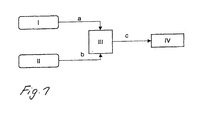
- an underwater vehicle which with oxygen a from a liquid storage I and a hydrocarbon b is supplied from a tank II, arises next electrical energy and heat by reaction of the hydrocarbon with the Oxygen is an exhaust gas c, which in addition to water mainly from carbon dioxide consists.
- This exhaust gas is detected in the device IV according to the method Claim 1 dissolved in water and given outboard.
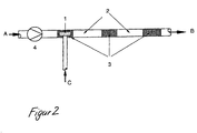
- a pipe section 2 is flown through from the inlet A to the outlet B by means of a pump 4 or by driving the vehicle with seawater.
- Appropriate flow velocities are in the range between 1 and 3 m / s.
- the diving pressure prevails.
- the exhaust gas C is discharged at a pressure higher than the submerged pressure through a porous body 1 inside this pipe.
- a sufficient pressure is achieved here by a suitable method in the energy converter III or a compressor in the exhaust stream c.
- the amount of seawater is determined so that the water can completely dissolve the exhaust gas due to its ability to dissolve gases. The necessary amount of water depends on the composition of the exhaust gas, the water temperature and the diving pressure.
Landscapes
- Chemical & Material Sciences (AREA)
- Chemical Kinetics & Catalysis (AREA)
- Engineering & Computer Science (AREA)
- Mechanical Engineering (AREA)
- Aviation & Aerospace Engineering (AREA)
- Treating Waste Gases (AREA)
- Exhaust Gas After Treatment (AREA)
- Other Liquid Machine Or Engine Such As Wave Power Use (AREA)
- Waste-Gas Treatment And Other Accessory Devices For Furnaces (AREA)
- Filling Or Discharging Of Gas Storage Vessels (AREA)
- Cylinder Crankcases Of Internal Combustion Engines (AREA)
Description
Energiewandler, die der außenluftunabhängigen Elektrizitätserzeugung auf Unterwasserfahrzeugen dienen, erzeugen bei Nutzung von Kohlenwasserstoffen als Energielieferant neben der Elektrizität auch Abgas.
Dieses Abgas muss an Bord gelagert oder aus dem Fahrzeug verbracht werden. Bekannte Lösungen hierfür sind Watermanagement-Systeme, Verflüssigung des Abgases und anschließende Lagerung oder die direkte Ausbringung als Gas.
Danach ist eine Vorrichtung vorgesehen, die ein Gehäuse mit einer kreisförmigen Innenlauffläche für einen rotierenden Kurvenkörper aufweist, wobei die Innenlauffläche unterbrochen ist durch sich gegenüberliegende Wassereintritts- und Wasseraustrittsöffnungspaare, bei denen jede Wassereintritisöffnung von der Wasseraustrittsöffnung durch einen auf dem Kurvenkörper radial verschiebbar geführten Schieber getrennt ist und von denen an der kreisförmigen Innenlauffläche des Gehäuses jeweils eine Wasserhochdruckeintrittsöffnung im Wechsel mit einer Wassemiederdruckaustrittsöffnung und einer Wasserniederdruckeintrittsöffnung im Wechsel mit einer Wasserhochdruckaustrittsöffnung angeordnet ist. Diese Vorrichtung zeichnet sich dadurch aus, daß sie nur wenig bewegte Teile und Dichtflächen aufweist und daß sie mit geringem inneren Strömungswiderstand, ohne Strömungsumkehr ein harmonisches, die wasserführenden Vorrichtungsteile somit schonendes und nur gering beanspruchendes Fließen des für die CO2-Entsorgung transportierten Wassers ermöglicht.
Die DE-A-26 58 484 bezieht sich auf einen thermodynamischen Unterwasserantrieb mit einer an ein Treibstoffzufuhrsystem angeschlossenen, einen Propeller antreibenden, außenluftunabhängigen Kraftmaschine, die eine die wassertöslichen Abgase ins Außenwasser abführende Auspuffleitung aufweist. Die Abgase strömen dabei zu einem sogenannten Turbulenzgitter, welches aus Horizontal- und Vertikalrohranlagen gebildet wird.
Die dabei entstehenden Gasblasen werden durch innerhalb der wasserdurchströmten Rohrstrecke angeordnete statische Mischer zerkleinert, wobei durch eine hohe Turbulenz der Flüssigkeit eine Auflösung des Gases erreicht wird. Erfindungsgemäß wird dabei das Abgas in die Rohrstrecke über einen porösen Körper eingeleitet, wobei die Rohrstrecke zwischen einem Einlass (A) und einem Auslass (B)über eine Pumpe mit Aussenbordwasser (Seewasser) versorgt wird.
Durch die Auflösung des Abgases innerhalb des Unterwasserfahrzeuges treten außerhalb des Bootes keine zu ortenden Gasblasen auf. Da der Arbeitsdruck des Verfahrens gleich dem Tauchdruck ist, wird nur wenig Energie verbraucht.
Nach einem bevorzugten Merkmal der Erfindung wird das Abgas über einen porösen Körper in die Rohrstrecke eingeleitet , wobei das Abgas vorzugsweise unter einem über dem Tauchdruck liegenden Druck in die Rohrstrecke eingebracht wird.
Die Strömungsgeschwindigkeit des Wassers innerhalb der Rohrstrecke beträgt nach einem weiteren Merkmal vorzugsweise 1 -3 m/s.
wobei im Bereich des Einlasses für das Außenbordwasser der Rohrstrecke eine Pumpe angeordnet ist und die Rohrimpfstelle aus einem 90° Rohrbogenstutzen mit Impflanze und einem porösen Körper besteht.
Die Länge der Rohrstrecke ist nach einem bevorzugten Merkmal der Erfindung so ausgeführt, dass diese eine vollständige Auflösung der Gasblasen des Abgases erlaubt.
- Figur 1:
- Außenluftunabhängige Energieversorgung,
- Figur 2:
- Vorrichtung zur Ausbringung des Abgases.
Die Menge des Seewassers wird so bestimmt, dass das Wasser aufgrund seines Lösungsvermögens für Gase das Abgas komplett lösen kann. Die notwendige Menge des Wassers hängt dabei von der Zusammensetzung des Abgases, der Wassertemperatur und dem Tauchdruck ab.
Durch Einsetzen der statischen Mischer 3 im Rohr 2 wird erreicht, dass sich aus dem Gas C sehr kleine Blasen bilden (< 3 mm), die durch die mittels der Mischer erzeugte hohe Turbulenz daran gehindert werden, sich zu größeren Blasen zu vereinigen. Durch die hohe Turbulenz und eine ausreichende Rohrlänge von beispielsweise ca. 30 m wird erreicht, dass sich die Blasen innerhalb des Rohres vollständig auflösen. Daher tritt an der Stelle B kein Gas mehr aus, welches zu orten wäre.
Claims (6)
- Verfahren zum signaturfreien Ausbringen von Abgas aus Unterwasserfahrzeugen, welches in Energiewandlem neben der Erzeugung von Elektroenergie anfällt, wobei das Abgas durch Druck in eine Rohrstrecke (2) geleitet wird, welche von Außenbordwasser durchströmt wird und die dabei entstehenden Gasblasen durch innerhalb der wasserdurchströmten Rohrstrecke (2) angeordnete statische Mischer (3) zerkleinert werden und durch eine hohe Turbulenz der Flüssigkeit eine Auflösung des Gases erreicht wird, dadurch gekennzeichnet, dass das Abgas in die Rohrstrecke (2) über einen porösen Körper (1) eingeleitet wird und die Rohrstrecke (2) zwischen einem Einlass (A) und einem Auslass (B) über eine Pumpe (4) mit Außenbordwasser (Seewasser) versorgt wird.
- Verfahren nach Anspruch 1, dadurch gekennzeichnet, dass die Rohrstrecke (2) durch die Fahrt des Unterwasserfahrzeuges mit Außenbordwasser (Seewasser) versorgt wird, wobei zwischen den Punkten A und B Tauchdruck herrscht.
- Verfahren nach einem der o. g. Ansprüche, dadurch gekennzeichnet, dass die Strömungsgeschwindigkeit des Wassers innerhalb der Rohrstrecke (2) 1 -3 m/s beträgt.
- Verfahren nach einem der o. g. Ansprüche, dadurch gekennzeichnet, dass das Abgas unter einem über dem Tauchdruck liegenden Druck in die Rohrstrecke (2) eingebracht wird.
- Vorrichtung zum signaturfreien Ausbringen von Abgas aus Unterwasserfahrzeugen, welches in Energiewandlem neben der Erzeugung von Elektroenergie anfällt, wobei im Unterwasserfahrzeug mindestens eine Rohrstrecke (2) angeordnet ist, welche einen Einlass (A) für Außenbordwasser (Seewasser), einen Auslass (B) für das im Wasser gelöste Abgas und eine Rohrimpfstelle für das in die Rohrstrecke (2) einzuleitende Abgas aufweist, wobei innerhalb der Rohrstrecke (2) mindestens ein statischer Mischer (3) vorgesehen ist, dadurch gekennzeichnet, dass im Bereich A der Rohrstrecke (2) eine Pumpe (4) angeordnet ist, und die Rohrimpfstelle aus einem 90° Rohrbogenstutzen mit Impflanze und einem porösen Körper (1) besteht.
- Vorrichtung nach Anspruch 5, dadurch gekennzeichnet, dass die Länge der Rohrstrecke (2) eine vollständige Auflösung der Gasblasen des Abgases erlaubt.
Applications Claiming Priority (3)
| Application Number | Priority Date | Filing Date | Title |
|---|---|---|---|
| DE10061487A DE10061487C1 (de) | 2000-12-09 | 2000-12-09 | Verfahren zum signaturfreien Ausbringen von Abgas aus Unterwasserfahrzeugen |
| DE10061487 | 2000-12-09 | ||
| PCT/DE2001/004140 WO2002046034A1 (de) | 2000-12-09 | 2001-11-05 | Verfahren zum signaturfreien ausbringen von abgas aus unterwasserfahrzeugen |
Publications (2)
| Publication Number | Publication Date |
|---|---|
| EP1252058A1 EP1252058A1 (de) | 2002-10-30 |
| EP1252058B1 true EP1252058B1 (de) | 2005-10-12 |
Family
ID=7666568
Family Applications (1)
| Application Number | Title | Priority Date | Filing Date |
|---|---|---|---|
| EP01999508A Expired - Lifetime EP1252058B1 (de) | 2000-12-09 | 2001-11-05 | Verfahren zum signaturfreien ausbringen von abgas aus unterwasserfahrzeugen |
Country Status (12)
| Country | Link |
|---|---|
| US (1) | US6736687B2 (de) |
| EP (1) | EP1252058B1 (de) |
| JP (1) | JP2004532761A (de) |
| KR (1) | KR100855399B1 (de) |
| AT (1) | ATE306417T1 (de) |
| AU (1) | AU782458B2 (de) |
| CA (1) | CA2396902C (de) |
| DE (3) | DE10061487C1 (de) |
| DK (1) | DK1252058T3 (de) |
| ES (1) | ES2250519T3 (de) |
| NO (1) | NO334678B1 (de) |
| WO (1) | WO2002046034A1 (de) |
Cited By (1)
| Publication number | Priority date | Publication date | Assignee | Title |
|---|---|---|---|---|
| DE102009051308A1 (de) | 2009-10-29 | 2011-05-05 | Howaldtswerke-Deutsche Werft Gmbh | Unterseeboot mit einer Anlage zur Ausbringung von Gas |
Families Citing this family (11)
| Publication number | Priority date | Publication date | Assignee | Title |
|---|---|---|---|---|
| FR2836983A1 (fr) * | 2002-03-11 | 2003-09-12 | Technicatome | Procede et dispositif d'evacuation de gaz d'une enceinte immergee |
| DE102004046820A1 (de) | 2004-03-29 | 2005-10-20 | Siemens Ag | Verfahren und Einrichtung zur Ausleitung der Abgase von Verbrennungskraftmaschinen von Schiffen in das Umgebungswasser der Schiffe |
| ES2287863T3 (es) * | 2004-03-29 | 2007-12-16 | Siemens Aktiengesellschaft | Instalacion de mezcla a vacio para gases de escape de buques. |
| DE502005006298D1 (de) | 2005-01-25 | 2009-01-29 | Siemens Ag | U-boot mit unterwasser-abgasausleitung bei schnorchelfahrt |
| DE102005007484A1 (de) | 2005-01-25 | 2006-07-27 | Siemens Ag | U-Boot mit Unterwasser-Abgasausleitung bei Schnorchelfahrt |
| ES2302644B1 (es) * | 2007-01-08 | 2009-05-25 | Hynergreen Technologies, S.A. | Sistema para impulsion de un fluido por recirculacion desde un medio a baja presion a un medio a alta presion. |
| DE102009040379B3 (de) * | 2009-09-07 | 2011-07-28 | Howaldtswerke-Deutsche Werft GmbH, 24143 | Unterseeboot mit einem Verdichter |
| US10300439B2 (en) | 2015-09-28 | 2019-05-28 | Hamilton Sundstrand Corporation | Systems and methods for gas disposal |
| US10589237B2 (en) | 2015-09-28 | 2020-03-17 | Hamilton Sundstrand Corporation | Systems and methods for gas disposal |
| CN112973383A (zh) * | 2019-12-14 | 2021-06-18 | 中国科学院大连化学物理研究所 | 一种水下用燃料电池尾气排放系统 |
| CN112594066B (zh) * | 2020-11-18 | 2022-12-02 | 西北工业大学 | 一种用于水下半闭式循环动力系统的废气增压排放装置 |
Family Cites Families (3)
| Publication number | Priority date | Publication date | Assignee | Title |
|---|---|---|---|---|
| FR766301A (de) * | 1933-03-18 | 1934-06-25 | ||
| DE2658484C2 (de) * | 1976-12-23 | 1985-04-04 | Messerschmitt-Bölkow-Blohm GmbH, 8000 München | Thermodynamischer Unterwasserantrieb |
| GB9513765D0 (en) * | 1995-07-06 | 1995-09-06 | Boc Group Plc | Production of argon |
-
2000
- 2000-12-09 DE DE10061487A patent/DE10061487C1/de not_active Expired - Fee Related
-
2001
- 2001-11-05 DE DE10195275T patent/DE10195275D2/de not_active Expired - Fee Related
- 2001-11-05 WO PCT/DE2001/004140 patent/WO2002046034A1/de not_active Ceased
- 2001-11-05 KR KR1020027009523A patent/KR100855399B1/ko not_active Expired - Fee Related
- 2001-11-05 CA CA002396902A patent/CA2396902C/en not_active Expired - Lifetime
- 2001-11-05 AU AU21544/02A patent/AU782458B2/en not_active Ceased
- 2001-11-05 JP JP2002547789A patent/JP2004532761A/ja active Pending
- 2001-11-05 ES ES01999508T patent/ES2250519T3/es not_active Expired - Lifetime
- 2001-11-05 DK DK01999508T patent/DK1252058T3/da active
- 2001-11-05 US US10/203,663 patent/US6736687B2/en not_active Expired - Lifetime
- 2001-11-05 EP EP01999508A patent/EP1252058B1/de not_active Expired - Lifetime
- 2001-11-05 AT AT01999508T patent/ATE306417T1/de not_active IP Right Cessation
- 2001-11-05 DE DE50107681T patent/DE50107681D1/de not_active Expired - Lifetime
-
2002
- 2002-07-11 NO NO20023339A patent/NO334678B1/no not_active IP Right Cessation
Cited By (2)
| Publication number | Priority date | Publication date | Assignee | Title |
|---|---|---|---|---|
| DE102009051308A1 (de) | 2009-10-29 | 2011-05-05 | Howaldtswerke-Deutsche Werft Gmbh | Unterseeboot mit einer Anlage zur Ausbringung von Gas |
| EP2330029A2 (de) | 2009-10-29 | 2011-06-08 | Howaldtswerke-Deutsche Werft Ag | Unterseeboot mit einer Anlage zur Ausbringung von Gas |
Also Published As
| Publication number | Publication date |
|---|---|
| JP2004532761A (ja) | 2004-10-28 |
| DK1252058T3 (da) | 2006-02-13 |
| US20030119388A1 (en) | 2003-06-26 |
| AU2154402A (en) | 2002-06-18 |
| DE10061487C1 (de) | 2002-03-21 |
| AU782458B2 (en) | 2005-07-28 |
| EP1252058A1 (de) | 2002-10-30 |
| DE50107681D1 (de) | 2006-02-23 |
| CA2396902C (en) | 2009-01-20 |
| WO2002046034B1 (de) | 2004-05-27 |
| NO334678B1 (no) | 2014-05-12 |
| NO20023339D0 (no) | 2002-07-11 |
| WO2002046034A1 (de) | 2002-06-13 |
| US6736687B2 (en) | 2004-05-18 |
| DE10195275D2 (de) | 2003-11-20 |
| KR100855399B1 (ko) | 2008-08-29 |
| KR20020087396A (ko) | 2002-11-22 |
| NO20023339L (no) | 2002-07-29 |
| CA2396902A1 (en) | 2002-06-13 |
| ES2250519T3 (es) | 2006-04-16 |
| ATE306417T1 (de) | 2005-10-15 |
Similar Documents
| Publication | Publication Date | Title |
|---|---|---|
| EP1252058B1 (de) | Verfahren zum signaturfreien ausbringen von abgas aus unterwasserfahrzeugen | |
| DE69605510T2 (de) | Einrichtung und verfahren zum entsalzen von meerwasser durch umkehrosmose mittels hydrostatischen drucks | |
| EP1599381B1 (de) | Schnelles, durch mindestens einen waterjet angetriebenes, schiff ohne abgasfahne | |
| DE2323029A1 (de) | Vorrichtung zur verstaerkung der schubkraft von wasserstrahl- und anderen antriebsaggregaten und ihre anwendung | |
| EP1582456A1 (de) | Unterdruck-Mischeinrichtung für Schiffsabgas | |
| DE1806471A1 (de) | Gasturbinentriebwerksanlage mit geschlossenem Kreislauf | |
| DE1294819B (de) | Verfahren zum Drosseln oder Verhindern des Stroemens eines Mediums durch eine Wandoeffnung von einem Raum hoeheren Druckes in einen Raum niederen Druckes und Anwendung des Verfahrens | |
| DE4312971C2 (de) | Vorrichtung und Verfahren zur Belüftung und Reinigung von Gewässern | |
| DE2658484C2 (de) | Thermodynamischer Unterwasserantrieb | |
| DE102009040379B3 (de) | Unterseeboot mit einem Verdichter | |
| CN217646214U (zh) | 一种用于船用碳捕集系统中的胺液静态混合器装置 | |
| CN119560191B (zh) | 一种非能动安全系统及水上平台 | |
| EP0752365B1 (de) | Vorrichtung für CO2-Entsorgung von Unterwasserfahrzeugen | |
| DE2459556A1 (de) | Verfahren zum blasenfreien antrieb von unterwasserfahrzeugen | |
| EP1730030B1 (de) | Verfahren und einrichtung zur ausleitung der abgase von verbrennungskraftmaschinen von schiffen in das umgebungswasser der schiffe | |
| DE9201154U1 (de) | Vorrichtung zum kontinuierlichen Einbringen von Gas in eine Flüssigkeit | |
| DE2426589A1 (de) | Antriebssystem mit mindestens einem hochdruckgasreaktor fuer untersee-boote | |
| DE102008044172A1 (de) | Hydraulisches Aggregat | |
| DE102005007484A1 (de) | U-Boot mit Unterwasser-Abgasausleitung bei Schnorchelfahrt | |
| DE8524206U1 (de) | Vorrichtung zur Gasinjektion in Flüssigkeiten | |
| DE475463C (de) | Verfahren zum Ausblasen der Tauchtanks bei Unterseebooten | |
| DE102022001910A1 (de) | Verfahren und Vorrichtung zur Erzeugung von Elektrizität ohne Einsatz von Primärenergie und Umweltbelastung | |
| DE3605260A1 (de) | Vorrichtung zur gasinjektion in fluessigkeiten | |
| EP3253651B1 (de) | Wasserfahrzeug | |
| DE2142568A1 (de) | Konstruktionsprinzip fuer einen grossen hochgeschwindigkeits- kavitations-hydroakustik - umlauftank |
Legal Events
| Date | Code | Title | Description |
|---|---|---|---|
| PUAI | Public reference made under article 153(3) epc to a published international application that has entered the european phase |
Free format text: ORIGINAL CODE: 0009012 |
|
| 17P | Request for examination filed |
Effective date: 20020620 |
|
| AK | Designated contracting states |
Kind code of ref document: A1 Designated state(s): AT BE CH CY DE DK ES FI FR GB GR IE IT LI LU MC NL PT SE TR |
|
| AX | Request for extension of the european patent |
Free format text: AL;LT;LV;MK;RO;SI |
|
| 17Q | First examination report despatched |
Effective date: 20040616 |
|
| RAP1 | Party data changed (applicant data changed or rights of an application transferred) |
Owner name: HOWALDTSWERKE-DEUTSCHE WERFT GMBH |
|
| GRAP | Despatch of communication of intention to grant a patent |
Free format text: ORIGINAL CODE: EPIDOSNIGR1 |
|
| GRAS | Grant fee paid |
Free format text: ORIGINAL CODE: EPIDOSNIGR3 |
|
| GRAA | (expected) grant |
Free format text: ORIGINAL CODE: 0009210 |
|
| AK | Designated contracting states |
Kind code of ref document: B1 Designated state(s): AT BE CH CY DE DK ES FI FR GB GR IE IT LI LU MC NL PT SE TR |
|
| PG25 | Lapsed in a contracting state [announced via postgrant information from national office to epo] |
Ref country code: FI Free format text: LAPSE BECAUSE OF FAILURE TO SUBMIT A TRANSLATION OF THE DESCRIPTION OR TO PAY THE FEE WITHIN THE PRESCRIBED TIME-LIMIT Effective date: 20051012 Ref country code: IE Free format text: LAPSE BECAUSE OF FAILURE TO SUBMIT A TRANSLATION OF THE DESCRIPTION OR TO PAY THE FEE WITHIN THE PRESCRIBED TIME-LIMIT Effective date: 20051012 |
|
| REG | Reference to a national code |
Ref country code: GB Ref legal event code: FG4D Free format text: NOT ENGLISH |
|
| REG | Reference to a national code |
Ref country code: CH Ref legal event code: EP |
|
| REG | Reference to a national code |
Ref country code: IE Ref legal event code: FG4D Free format text: LANGUAGE OF EP DOCUMENT: GERMAN |
|
| PG25 | Lapsed in a contracting state [announced via postgrant information from national office to epo] |
Ref country code: AT Free format text: LAPSE BECAUSE OF NON-PAYMENT OF DUE FEES Effective date: 20051105 Ref country code: CY Free format text: LAPSE BECAUSE OF FAILURE TO SUBMIT A TRANSLATION OF THE DESCRIPTION OR TO PAY THE FEE WITHIN THE PRESCRIBED TIME-LIMIT Effective date: 20051105 |
|
| PG25 | Lapsed in a contracting state [announced via postgrant information from national office to epo] |
Ref country code: CH Free format text: LAPSE BECAUSE OF NON-PAYMENT OF DUE FEES Effective date: 20051130 Ref country code: LI Free format text: LAPSE BECAUSE OF NON-PAYMENT OF DUE FEES Effective date: 20051130 Ref country code: MC Free format text: LAPSE BECAUSE OF NON-PAYMENT OF DUE FEES Effective date: 20051130 |
|
| PG25 | Lapsed in a contracting state [announced via postgrant information from national office to epo] |
Ref country code: LU Free format text: LAPSE BECAUSE OF NON-PAYMENT OF DUE FEES Effective date: 20051212 |
|
| GBT | Gb: translation of ep patent filed (gb section 77(6)(a)/1977) |
Effective date: 20051208 |
|
| REG | Reference to a national code |
Ref country code: SE Ref legal event code: TRGR |
|
| PG25 | Lapsed in a contracting state [announced via postgrant information from national office to epo] |
Ref country code: GR Free format text: LAPSE BECAUSE OF FAILURE TO SUBMIT A TRANSLATION OF THE DESCRIPTION OR TO PAY THE FEE WITHIN THE PRESCRIBED TIME-LIMIT Effective date: 20060112 |
|
| REG | Reference to a national code |
Ref country code: DK Ref legal event code: T3 |
|
| REF | Corresponds to: |
Ref document number: 50107681 Country of ref document: DE Date of ref document: 20060223 Kind code of ref document: P |
|
| REG | Reference to a national code |
Ref country code: ES Ref legal event code: FG2A Ref document number: 2250519 Country of ref document: ES Kind code of ref document: T3 |
|
| REG | Reference to a national code |
Ref country code: IE Ref legal event code: FD4D |
|
| ET | Fr: translation filed | ||
| REG | Reference to a national code |
Ref country code: CH Ref legal event code: PL |
|
| PLBE | No opposition filed within time limit |
Free format text: ORIGINAL CODE: 0009261 |
|
| STAA | Information on the status of an ep patent application or granted ep patent |
Free format text: STATUS: NO OPPOSITION FILED WITHIN TIME LIMIT |
|
| 26N | No opposition filed |
Effective date: 20060713 |
|
| REG | Reference to a national code |
Ref country code: DE Ref legal event code: R082 Ref document number: 50107681 Country of ref document: DE Representative=s name: PATENTANWAELTE BRESSEL UND PARTNER, DE |
|
| REG | Reference to a national code |
Ref country code: FR Ref legal event code: CD Owner name: THYSSENKRUPP MARINE SYSTEMS GMBH Effective date: 20131230 |
|
| REG | Reference to a national code |
Ref country code: DE Ref legal event code: R082 Ref document number: 50107681 Country of ref document: DE Representative=s name: PATENTANWAELTE BRESSEL UND PARTNER MBB, DE Effective date: 20140103 Ref country code: DE Ref legal event code: R081 Ref document number: 50107681 Country of ref document: DE Owner name: THYSSENKRUPP MARINE SYSTEMS GMBH, DE Free format text: FORMER OWNER: HOWALDTSWERKE-DEUTSCHE WERFT GMBH, 24143 KIEL, DE Effective date: 20140103 |
|
| REG | Reference to a national code |
Ref country code: NL Ref legal event code: TD Effective date: 20140219 |
|
| REG | Reference to a national code |
Ref country code: DE Ref legal event code: R084 Ref document number: 50107681 Country of ref document: DE |
|
| REG | Reference to a national code |
Ref country code: DE Ref legal event code: R084 Ref document number: 50107681 Country of ref document: DE Effective date: 20150206 |
|
| REG | Reference to a national code |
Ref country code: FR Ref legal event code: PLFP Year of fee payment: 15 |
|
| REG | Reference to a national code |
Ref country code: FR Ref legal event code: PLFP Year of fee payment: 16 |
|
| REG | Reference to a national code |
Ref country code: FR Ref legal event code: PLFP Year of fee payment: 17 |
|
| REG | Reference to a national code |
Ref country code: DE Ref legal event code: R082 Ref document number: 50107681 Country of ref document: DE Representative=s name: PATENTANWAELTE BRESSEL UND PARTNER MBB, DE Ref country code: DE Ref legal event code: R081 Ref document number: 50107681 Country of ref document: DE Owner name: THYSSENKRUPP MARINE SYSTEMS GMBH, DE Free format text: FORMER OWNER: THYSSENKRUPP MARINE SYSTEMS GMBH, 24143 KIEL, DE |
|
| PGFP | Annual fee paid to national office [announced via postgrant information from national office to epo] |
Ref country code: DE Payment date: 20191121 Year of fee payment: 19 Ref country code: SE Payment date: 20191121 Year of fee payment: 19 Ref country code: NL Payment date: 20191120 Year of fee payment: 19 Ref country code: PT Payment date: 20191104 Year of fee payment: 19 |
|
| PGFP | Annual fee paid to national office [announced via postgrant information from national office to epo] |
Ref country code: FR Payment date: 20191120 Year of fee payment: 19 Ref country code: DK Payment date: 20191122 Year of fee payment: 19 Ref country code: ES Payment date: 20191220 Year of fee payment: 19 Ref country code: IT Payment date: 20191128 Year of fee payment: 19 Ref country code: BE Payment date: 20191120 Year of fee payment: 19 |
|
| PGFP | Annual fee paid to national office [announced via postgrant information from national office to epo] |
Ref country code: TR Payment date: 20191104 Year of fee payment: 19 |
|
| PGFP | Annual fee paid to national office [announced via postgrant information from national office to epo] |
Ref country code: GB Payment date: 20191120 Year of fee payment: 19 |
|
| REG | Reference to a national code |
Ref country code: DE Ref legal event code: R119 Ref document number: 50107681 Country of ref document: DE |
|
| REG | Reference to a national code |
Ref country code: DK Ref legal event code: EBP Effective date: 20201130 |
|
| REG | Reference to a national code |
Ref country code: SE Ref legal event code: EUG |
|
| REG | Reference to a national code |
Ref country code: NL Ref legal event code: MM Effective date: 20201201 |
|
| GBPC | Gb: european patent ceased through non-payment of renewal fee |
Effective date: 20201105 |
|
| PG25 | Lapsed in a contracting state [announced via postgrant information from national office to epo] |
Ref country code: PT Free format text: LAPSE BECAUSE OF NON-PAYMENT OF DUE FEES Effective date: 20210505 |
|
| REG | Reference to a national code |
Ref country code: BE Ref legal event code: MM Effective date: 20201130 |
|
| PG25 | Lapsed in a contracting state [announced via postgrant information from national office to epo] |
Ref country code: NL Free format text: LAPSE BECAUSE OF NON-PAYMENT OF DUE FEES Effective date: 20201201 Ref country code: SE Free format text: LAPSE BECAUSE OF NON-PAYMENT OF DUE FEES Effective date: 20201106 |
|
| PG25 | Lapsed in a contracting state [announced via postgrant information from national office to epo] |
Ref country code: IT Free format text: LAPSE BECAUSE OF NON-PAYMENT OF DUE FEES Effective date: 20201105 Ref country code: FR Free format text: LAPSE BECAUSE OF NON-PAYMENT OF DUE FEES Effective date: 20201130 |
|
| PG25 | Lapsed in a contracting state [announced via postgrant information from national office to epo] |
Ref country code: DE Free format text: LAPSE BECAUSE OF NON-PAYMENT OF DUE FEES Effective date: 20210601 Ref country code: GB Free format text: LAPSE BECAUSE OF NON-PAYMENT OF DUE FEES Effective date: 20201105 Ref country code: DK Free format text: LAPSE BECAUSE OF NON-PAYMENT OF DUE FEES Effective date: 20201130 |
|
| PG25 | Lapsed in a contracting state [announced via postgrant information from national office to epo] |
Ref country code: PT Free format text: LAPSE BECAUSE OF EXPIRATION OF PROTECTION Effective date: 20211115 |
|
| REG | Reference to a national code |
Ref country code: ES Ref legal event code: FD2A Effective date: 20220131 |
|
| PG25 | Lapsed in a contracting state [announced via postgrant information from national office to epo] |
Ref country code: ES Free format text: LAPSE BECAUSE OF NON-PAYMENT OF DUE FEES Effective date: 20201106 |
|
| PG25 | Lapsed in a contracting state [announced via postgrant information from national office to epo] |
Ref country code: TR Free format text: LAPSE BECAUSE OF NON-PAYMENT OF DUE FEES Effective date: 20201105 |
|
| PG25 | Lapsed in a contracting state [announced via postgrant information from national office to epo] |
Ref country code: BE Free format text: LAPSE BECAUSE OF NON-PAYMENT OF DUE FEES Effective date: 20201130 |
|
| PG25 | Lapsed in a contracting state [announced via postgrant information from national office to epo] |
Ref country code: PT Free format text: LAPSE BECAUSE OF NON-PAYMENT OF DUE FEES Effective date: 20201105 |
|
| PG25 | Lapsed in a contracting state [announced via postgrant information from national office to epo] |
Ref country code: PT Free format text: LAPSE BECAUSE OF NON-PAYMENT OF DUE FEES Effective date: 20201105 |