EP1251990B1 - Seilsäge - Google Patents
Seilsäge Download PDFInfo
- Publication number
- EP1251990B1 EP1251990B1 EP01901103A EP01901103A EP1251990B1 EP 1251990 B1 EP1251990 B1 EP 1251990B1 EP 01901103 A EP01901103 A EP 01901103A EP 01901103 A EP01901103 A EP 01901103A EP 1251990 B1 EP1251990 B1 EP 1251990B1
- Authority
- EP
- European Patent Office
- Prior art keywords
- cable
- rope
- saw
- sawing
- saw device
- Prior art date
- Legal status (The legal status is an assumption and is not a legal conclusion. Google has not performed a legal analysis and makes no representation as to the accuracy of the status listed.)
- Expired - Lifetime
Links
Images


Classifications
-
- B—PERFORMING OPERATIONS; TRANSPORTING
- B23—MACHINE TOOLS; METAL-WORKING NOT OTHERWISE PROVIDED FOR
- B23D—PLANING; SLOTTING; SHEARING; BROACHING; SAWING; FILING; SCRAPING; LIKE OPERATIONS FOR WORKING METAL BY REMOVING MATERIAL, NOT OTHERWISE PROVIDED FOR
- B23D57/00—Sawing machines or sawing devices not covered by one of the preceding groups B23D45/00 - B23D55/00
- B23D57/003—Sawing machines or sawing devices working with saw wires, characterised only by constructional features of particular parts
- B23D57/0053—Sawing machines or sawing devices working with saw wires, characterised only by constructional features of particular parts of drives for saw wires; of wheel mountings; of wheels
-
- B—PERFORMING OPERATIONS; TRANSPORTING
- B28—WORKING CEMENT, CLAY, OR STONE
- B28D—WORKING STONE OR STONE-LIKE MATERIALS
- B28D1/00—Working stone or stone-like materials, e.g. brick, concrete or glass, not provided for elsewhere; Machines, devices, tools therefor
- B28D1/02—Working stone or stone-like materials, e.g. brick, concrete or glass, not provided for elsewhere; Machines, devices, tools therefor by sawing
- B28D1/08—Working stone or stone-like materials, e.g. brick, concrete or glass, not provided for elsewhere; Machines, devices, tools therefor by sawing with saw-blades of endless cutter-type, e.g. chain saws, i.e. saw chains, strap saws
- B28D1/088—Sawing in situ, e.g. stones from rocks, grooves in walls
-
- Y—GENERAL TAGGING OF NEW TECHNOLOGICAL DEVELOPMENTS; GENERAL TAGGING OF CROSS-SECTIONAL TECHNOLOGIES SPANNING OVER SEVERAL SECTIONS OF THE IPC; TECHNICAL SUBJECTS COVERED BY FORMER USPC CROSS-REFERENCE ART COLLECTIONS [XRACs] AND DIGESTS
- Y10—TECHNICAL SUBJECTS COVERED BY FORMER USPC
- Y10T—TECHNICAL SUBJECTS COVERED BY FORMER US CLASSIFICATION
- Y10T83/00—Cutting
- Y10T83/424—By increased tensioning of work-enclosing wire
-
- Y—GENERAL TAGGING OF NEW TECHNOLOGICAL DEVELOPMENTS; GENERAL TAGGING OF CROSS-SECTIONAL TECHNOLOGIES SPANNING OVER SEVERAL SECTIONS OF THE IPC; TECHNICAL SUBJECTS COVERED BY FORMER USPC CROSS-REFERENCE ART COLLECTIONS [XRACs] AND DIGESTS
- Y10—TECHNICAL SUBJECTS COVERED BY FORMER USPC
- Y10T—TECHNICAL SUBJECTS COVERED BY FORMER US CLASSIFICATION
- Y10T83/00—Cutting
- Y10T83/929—Tool or tool with support
- Y10T83/9292—Wire tool
Definitions
- the invention relates to a wire saw as they e.g. Example from WO 95/28263 is known.
- Rope saws are known from the prior art which have an endlessly revolving rope have by means of stone, concrete, masonry, etc. can be separated.
- the rope released when cutting requires storage. This will e.g. thereby solved that the released rope is stored in a machine by the distance between correspondingly arranged deflection rollers is varied.
- Pulley batteries arranged in a pulley-like manner is a very efficient rope storage possible because a lot of rope can be stored with small movements can.
- a wire saw device which has a wire storage with two roller batteries. Outside of the rope storage is a Drive wheel. The roller batteries have no active drive.
- a sawing device is known from WO95 / 18692. This has several pulleys which are essentially all arranged in one plane. This System builds very large and is therefore not suitable for use in confined spaces suitable. The drive acts concentrated on the saw cable in one place.
- the invention disclosed here is based inter alia on on targeted management of the Forces and their distribution within a wire saw device, especially in a wire saw.
- the intention is to distribute the force in the saw cable. This eliminates local overloads and overvoltages.
- the philosophy The invention disclosed here includes in cutting the saw wire in sections and to drive with coordinated loads. Controlled adjustable Normal forces on the rope within a rope storage allow optimal traction.
- the drive means and the drive power / speed transmitted by them are preferably individually adjustable. An overload of the saw cable, especially when starting, is thus avoided and secondary stresses prevented.
- the invention enables the saw cable, especially when starting, controlled in a cut.
- the invention disclosed herein preferably uses one distributed load transfer into the saw cable, an intermediate storage concept and an adaptive one Feed system that simplifies the "sawing" operating mode.
- the loads initiated are coordinated and coordinated with each other by means of compensating means.
- an actively driven cable storage device e.g. consists of shafts arranged in parallel, on which several lie side by side Rollers are arranged such that the saw cable the roles of Continuously wraps around the rope storage.
- the distance between certain shaft axes is preferred continuously adjustable so that the storage volume of the rope storage and the gear ratio of the feed can be changed.
- the side by side lying roles are advantageously arranged so that they are from a Side are freely accessible, so that a closed rope can be attached in loops without having to open the rope.
- the roles of the rope storage are advantageously not arranged in one level, since a corresponding arrangement can counteract the achievable efficiency.
- the rope storage is driven usually over several arranged in the area (within) the rope storage Roll. These roles are operatively connected to one another via compensating means, that they enable and balance a variable distribution of the drive power. In particular, different speeds of the saw cable are during the transmission of the drive power can be compensated. In the area of the rope storage If necessary, additional funds are provided for active control of the saw cable.
- These are preferably means for measuring and Checking the rope tension, e.g. rope brakes, etc.
- the individual drive means can be coordinated with each other in such a way that the rope tension inside and outside the Rope storage, especially when starting, is specifically controlled and adjustable.
- this is Saw wire in the invention disclosed herein at several locations along its length and driven between mechanical resistors.
- This creates a local Overloading of the saw cable and the associated signs of wear or even rope breaks avoided.
- Cable saw device the usual high forces do not occur on.
- the load on the individual drive points can be adjusted as required in such a way that optimal traction is achieved.
- This is achieved in particular by using optimal Rope tension in the free saw rope when starting up and an adaptive rope tension is made possible when sawing. Seen procedurally, locally different Speeds in a saw rope of a wire saw device, with several driving rope pulleys, balanced by forces of Transfer faster running rope sections to slower running rope sections become.
- the multiple roller drive used here allows a largely, even when using a rope storage tension-free running of the saw cable into the cut. Normal forces in As a result, cuts are low and the required starting torque is kept low. If necessary, you can do this by "clamping" the saw cable in the drive system optimal traction of the drive wheels can be achieved. If necessary, it will Saw rope is delayed before entering the rope storage, so that an increased Traction in the rope storage (drive) is reached.
- one or several, spring-loaded rollers pressure rollers, jockey rollers
- the operation of the drive system is greatly simplified, there is already a controlled low tension of the rope in the cut one enables reliable rope guidance during start-up. This bias can be defined before starting up.
- the invention disclosed here has a preferably adaptive character.
- the invention is designed so that the rope tension and thus the normal forces in the cut are kept as constant as possible so that large load changes and voltage peaks be avoided.
- the basis for this is, among others a rope stretcher, also feed system called that have no significant self-locking.
- hydraulic and pneumatic systems are preferred.
- hydraulic Systems also have the advantage of higher passive safety because they do not transfer any storage energy to the rope stretcher in the event of a rope break. Thereby prevents the saw cable from being tightened unnecessarily.
- the length of the working saw cable can be determined by the distance between the shafts Advantage laterally side by side rope pulleys can be determined.
- Certain cable deflection rollers transmit driving forces to the saw cable. These roles can be arranged on the same or on different waves his. In particular, they can have the same or different drive means are driven.
- the driving means are preferably along the saw cable from each other in regular or irregular (suppress any Vibrations) intervals arranged so that the drive power is gentle and is continuously transferred to the saw cable. In contrast to the state of the Technology should prefer the multiple drive rollers between mechanical resistances be arranged.
- the invention disclosed here is based inter alia on on the realization that a balance in a cable store with the multiple drive means acting on a saw cable must be coordinated. A corresponding compensatory movement is different Way realized.
- the size of the rope store of the ones disclosed here In contrast to the rope stores known from the prior art, the invention is not limited. More than two drive rollers are not a problem. Because of the distributed load transfer and the coordinated coupling the driving drive rollers, as well as their arrangement, are from a standing start problems specifically known in the art avoided. You can also use the invention disclosed here realize compact rope storage of any size.
- a preferred embodiment of a wire saw device according to the invention with a saw cable has a cable storage device for receiving a saw cable.
- This consists of several rope pulleys, at least two of these rope pulleys have a variable distance from each other. This allows change the length of the saw wire deflected in the wire saw device.
- On The motor drives the saw cable via several cable pulleys. Locally different Saw cable speeds are between the several driving cable pulleys compensated by means of compensation.
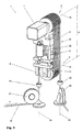
- FIG. 1 schematically shows a preferred embodiment of a wire saw device 1 according to the invention.
- a first roller battery 5, a second roller battery 6 and a motor 7 which is fastened to a first holding device 8 can be seen.
- the roller batteries 5, 6 here consist of several axially adjacent rollers.
- the first roller battery 5 here consists of six rollers, which are operatively connected to a drive axle (not shown in detail) of the motor 7.
- the first holding device 8 here has two spars 9, along which a second Holding device 10 is slidably mounted.
- the second roller battery 6 is on the second, slidable holding device 10 attached such that the rollers of the second roller battery 6 are freely rotatable about a first axis 15.
- the roles of first roller battery 5 are arranged here on a second axis 16, which essentially aligned with the drive axis (not shown in detail) of the motor 7.
- the first and second axes 15, 16 are arranged essentially parallel here.
- On Hydraulic cylinder 20, which with the first and with the second holding device 8, 10th is functionally connected, serves to determine and change a distance A between the first and the second roller battery 5, 6, in particular during a cutting process.
- a saw cable 25 extends here from a first, around a third axis 26 pivotable deflection roller 27, on the rollers of the first 5 and the second roller battery 6 and via a second deflecting roller which can be pivoted about a fourth axis 28 29.
- the first and the second roller battery 5,6 act as a cable storage 30, which for Picking up the released saw cable 25, in particular, during a cutting process serves.
- roller batteries 5, 6 are arranged such that the rope (when the device is stationary) freely accessible in the rope storage can be attached.
- Rope guide here in Form of a first 34 and a second eyelet 35 are also designed so that the saw cable 25 can be attached in a freely accessible manner.
- the second guide roller 29 and the second eyelet 35 are arranged such that they can move towards the first if necessary Axis 15 are displaceable. This allows not all turns in the rope storage must be occupied.
- the saw cable 25, which the cable saw device 1 here in the direction of an arrow P passes through, is driven by the motor 7 via the first roller battery 5.
- the Rolls of the roll battery 5 are not rigidly connected to the motor 7, but have, especially with each other active connections, which individual rope speeds and the associated speed differences and enable different power transmissions. Especially when there is a change the length of the saw cable, it is necessary that relative movements are permitted are.
- the operative connections between the rollers of the first roller battery are such trained that the forces transmitted to the saw cable 25 are not in one place be initiated in a concentrated manner. It is due to the configuration according to the invention much more possible to transfer the forces as needed.
- the forces in the part of the saw cable 25 is located inside the cable storage 30 to increase during which the Forces of the section of the saw cable 25 in the section correspondingly lower are. This will increase traction while maintaining optimal load on the Saw rope reached. It is advantageous, e.g. especially when starting off when certain Elements to increase traction are braked in a controlled manner.
- the one shown here Embodiment can do this, for example, by braking the first Guide roller 27 can be reached.
- Other means can also be used as equivalents become.
- the different Permits rope speeds In the operative connections between the roles of the roller battery 5 with each other and the motor 7 can be used, for example, a freewheel, the different Permits rope speeds. Means of compensation are advantageous of different rope speeds, respectively. Rope forces. Such means exist for example from differential gears (differential gears), slip clutches, hydraulic couplings (viscous couplings) or different, adapted Roll diameter. The maximum forces of the saw cable 25 are preferred controlled via load-limiting elements, for example in the form of slip clutches. Vibrations and load peaks are dampened efficiently. To speed differences to compensate for the roles of the roller batteries 5.6 if necessary have adapted different diameters. The pulleys 5, 6, 27, 29 are cooled with water if necessary, respectively. cleaned to a to guarantee optimal operation.
- the saw cable 25 can be driven by one or more motors 7.
- Motors 7 are preferably used hydraulic or electric motors, which are preferably arranged spaced along the rope acting around a distributed Guarantee load introduction. These are linked to each other in such a way that different speeds in the rope speed adjustable, respectively. are compensable. In the case of hydraulic motors, this is done, for example, via corresponding ones Valves controllable, which influence the volume flows in the hydraulics.
- FIG. 2 shows the wire saw device 1 according to FIG. 1 with an extended wire storage 30.
- the wire storage 30 here additionally has three further roller batteries 38, 39, 40. These roller batteries are arranged in such a way that they allow flexible adjustment of the length of the saw cable 25. The rollers are freely accessible from one side in such a way that easy handling of the saw cable is guaranteed. As shown, it is not necessary that all roles are filled. If necessary, the cable storage 30 can be expanded accordingly.
- the roller batteries 6, 38, 39, 40 can have additional means for checking and monitoring the rope tension, if necessary.
- Means for driving the saw cable 25 Particularly suitable are so-called jockey rollers, which enable adaptive control and smoothing of the cable tension. These are resiliently arranged rollers that adapt to the rope tension. If necessary, these can also have a delaying effect. If necessary, the rope guide can be supplemented and checked by appropriate means.
- FIG. 3 schematically shows a possible tension curve of a saw cable 25 in an intersection area 43 and in the area 44 of a cable store 30.
- the length of a saw cable 25 is shown schematically and on an ordinate 42 the forces prevailing in the saw cable.
- the forces in the Cutting area 43 to a maximum value of 45 and are then in the area 44 of a cable store for example controlled by means of slips using the means provided for this purpose reduced.
- Means to limit the maximum permissible forces within of a saw cable consist, for example, of slip clutches, hydraulic ones Couplings, electrical means (current limiter), sliding friction number of those involved Materials (role, rope), etc. They can be specifically adjusted and limit the maximum possible load on a limit value 46. This is selected such that there is no excessive stress on the saw cable or the cable saw device.
- FIG 4 shows schematically a possible force, respectively.
- the length of a saw cable 25 is shown schematically on an abscissa 41 and the forces prevailing in the saw cable are shown on an ordinate 42.
- the forces in a cutting area 43 are small in comparison to the area 44 of a cable storage device 30.
- the traction within the cable storage 30 is significantly increased.
- the forces in the saw cable 25 when starting in the cutting area 43 are low, which minimizes the loads acting on the saw cable 25.
- the tensions in the saw cable 25 are specifically increased in the region of the entry of the saw cable into the cable storage 30, for example by means of a braked roller (including a jockey roller) or another means. This delay is switched off when the "Sawing" operating state is reached.
Description
- Figur 1
- schematisch eine Seilsägevorrichtung in perspektivischer Ansicht;
- Figur 2
- zeigt schematisch die Seilsägevorrichtung gemäss Figur 1 mit einem erweiterten Seilspeicher;
- Figur 3
- zeigt schematisch einen möglichen Spannungsverlauf eines Sägeseils beim Sägen;
- Figur 4
- zeigt schematisch einen möglichen Spannungsverlauf eines Sägeseils beim Anfahren (Hochfahren).
Claims (10)
- Seilsägevorrichtung (1) mit einem Seilspeicher (30), zur Aufnahme eines Sägeseils (25), mit einer ersten und einer zweiten Rollenbatterie (5, 6) mit mehreren axial nebeneinander angeordneten Seilumlenkrollen, wobei die erste und die zweite Rollenbaterie (5, 6) zueinander in einem veränderbaren Abstand (A) angeordnet sind, so, dass die Länge des im Seilspeicher (30) gespeicherten Sägeseils (25) beim Sägeprozess einstellbar ist, wobei mehrere Seilumlenkrollen (5) des Seilspeichers (30) angetrieben sind, derart, dass die Antriebskräfte verteilt ins Sägeseil (25) eingeleitet werden und unterschiedliche Seilspannungen (P), respektive Seilgeschwindigkeiten im Sägeseil (25) zwischen den antreibenden Seilumlenkrollen (5), die sich als Folge einer Veränderung des Abstands (A) zwischen den beiden Rollenbatterien (5, 6) ergeben, durch Ausgleichsmittel ausgeglichen werden.
- Seilsägevorrichtung (1) gemäss Patentanspruch 1, dadurch gekennzeichnet, dass die antreibenden Seilumlenkrollen (5) über mindestens ein Ausgleichsmittel wirkverbunden sind, derart dass unterschiedliche Seilspannungen (P), respektive Seilgeschwindigkeiten im Sägeseil (25) zwischen den antreibenden Seilumlenkrollen (5) ausgeglichen werden.
- Seilsägevorrichtung (1) gemäss Patentanspruch 2, dadurch gekennzeichnet, dass das Ausgleichsmittel eine Rutschkupplung, eine hydraulische Kupplung, eine Freilaufkupplung oder ein Ausgleichsgetriebe ist.
- Seilsägevorrichtung (1) gemäss einem der vorangehenden Patentansprüche, dadurch gekennzeichnet, dass die Seilumlenkrollen (5) einer Rollenbatterle (5) über einen Motor (7) angetrieben werden.
- Seilsägevorrichtung (1) gemäss einem der vorangehenden Patentsansprüche, dadurch gekennzeichnet, dass die Rollen der Rollenbatterien (5, 6) von einer Seite frei zugänglich sind, derart, dass ein geschlossenes Sägeseil (25) in Schlaufen aufbringbar ist.
- Seilsägevorrichtung (1) gemäss einem der vorangehenden Patentansprüche, gekennzeichnet durch, mehr als zwei Rollenbatterien (5, 6, 38, 39, 40).
- Seilsägevorrichtung (1) gemäss einem der vorangehenden Patentansprüche, dadurch gekennzeichnet, dass das Vorschubsystem (20), welches den Abstand (A) zwischen den Rollenbatterien (5, 6) verändert, adaptiv ausgestaltet ist.
- Seilsägevorrichtung (1) gemäss einem der vorangehenden Patentansprüche, dadurch gekennzeichnet, dass das Sägeseil (25) im Seilspeicher (30) eingespannt wird, derart, dass insbesondere beim Anfahren, eine optimale Traktion der antreibenden Umlenkrollen (5) resultiert.
- Seilsägevorrichtung (1) gemäss Patentanspruch 8, dadurch gekennzeichnet, dass eine Seilumlenkrolle eine Bremse aufweist, derart, dass die Traktion im Seilspeicher (30) erhöht wird.
- Seilsägevorrichtung (1) gemäss einem der vorangehenden Patentansprüche, gekennzeichnet durch, eine Jockey-Rolle die zur adaptiven Kontrolle und Glättung der Seilspannungen (P) dient.
Applications Claiming Priority (5)
| Application Number | Priority Date | Filing Date | Title |
|---|---|---|---|
| CH184002000 | 2000-01-31 | ||
| CH1842000 | 2000-01-31 | ||
| CH146600 | 2000-07-25 | ||
| CH14662000 | 2000-07-25 | ||
| PCT/CH2001/000065 WO2001056729A1 (de) | 2000-01-31 | 2001-01-29 | Seilsäge |
Publications (2)
| Publication Number | Publication Date |
|---|---|
| EP1251990A1 EP1251990A1 (de) | 2002-10-30 |
| EP1251990B1 true EP1251990B1 (de) | 2003-10-22 |
Family
ID=25720983
Family Applications (1)
| Application Number | Title | Priority Date | Filing Date |
|---|---|---|---|
| EP01901103A Expired - Lifetime EP1251990B1 (de) | 2000-01-31 | 2001-01-29 | Seilsäge |
Country Status (6)
| Country | Link |
|---|---|
| US (1) | US6920871B2 (de) |
| EP (1) | EP1251990B1 (de) |
| AT (1) | ATE252438T1 (de) |
| AU (1) | AU2001226612A1 (de) |
| DE (1) | DE50100832D1 (de) |
| WO (1) | WO2001056729A1 (de) |
Cited By (3)
| Publication number | Priority date | Publication date | Assignee | Title |
|---|---|---|---|---|
| DE102004012606B4 (de) * | 2004-03-12 | 2007-06-14 | Cedima Diamantwerkzeug- Und Maschinenhandelsgesellschaft Mbh | Schutzvorrichtung für Seilsägevorrichtungen |
| DE102007008124A1 (de) | 2007-02-19 | 2008-08-21 | Cedima Diamantwerkzeug- Und Maschinenbaugesellschaft Mbh | Seilsägesystem für den Natursteinbereich |
| DE102007008123A1 (de) | 2007-02-19 | 2008-08-21 | Cedima Diamantwerkzeug- Und Maschinenbaugesellschaft Mbh | Vorrichtung zur Erfassung eines Seilrisses eines Sägeseils von Seilsägemaschinen |
Families Citing this family (11)
| Publication number | Priority date | Publication date | Assignee | Title |
|---|---|---|---|---|
| US20090122637A1 (en) * | 2007-11-14 | 2009-05-14 | Jan Kruyer | Sinusoidal mixing and shearing apparatus and associated methods |
| US20090139905A1 (en) * | 2007-11-30 | 2009-06-04 | Jan Kruyer | Endless cable system and associated methods |
| US20090139906A1 (en) * | 2007-11-30 | 2009-06-04 | Jan Kruyer | Isoelectric separation of oil sands |
| US20100126488A1 (en) * | 2008-11-25 | 2010-05-27 | Abhaya Kumar Bakshi | Method and apparatus for cutting wafers by wire sawing |
| US8065995B2 (en) * | 2008-11-25 | 2011-11-29 | Cambridge Energy Resources Inc | Method and apparatus for cutting and cleaning wafers in a wire saw |
| US8261730B2 (en) * | 2008-11-25 | 2012-09-11 | Cambridge Energy Resources Inc | In-situ wafer processing system and method |
| WO2010128903A1 (en) * | 2009-05-04 | 2010-11-11 | Husqvarna Ab | A wire saw and a method of rebuilding a wall saw to a wire saw |
| IT1401683B1 (it) * | 2010-08-27 | 2013-08-02 | Gambini Int Sa | Dispositivo di taglio per rotoli di materiale nastriforme, in particolare cartaceo. |
| MX2016008543A (es) * | 2013-12-30 | 2016-12-09 | Bp Corp North America Inc | Aparato de preparacion de muestras para simulacion numerica directa de propiedades de roca. |
| US9561553B2 (en) * | 2014-04-01 | 2017-02-07 | Richard A. Waida, JR. | Transportable horizontal bandsaw assembly |
| FR3071183B1 (fr) * | 2017-09-21 | 2019-12-20 | Saint-Gobain Placo | Procede et dispositif de decoupe d'un matelas ou d'un panneau en laine minerale ou d'une plaque ou d'un panneau en materiau de construction poreux |
Family Cites Families (5)
| Publication number | Priority date | Publication date | Assignee | Title |
|---|---|---|---|---|
| US3824982A (en) * | 1971-12-20 | 1974-07-23 | Motorola Inc | Machine for cutting brittle materials |
| JPH049138Y2 (de) * | 1986-04-12 | 1992-03-06 | ||
| CH669554A5 (de) * | 1987-02-18 | 1989-03-31 | Forbeton Betonbohr S A | |
| JPS6422406U (de) * | 1987-07-31 | 1989-02-06 | ||
| DE29805457U1 (de) * | 1998-03-26 | 1998-07-23 | Cedima Diamantwerkzeug Masch | Seilsägevorrichtung |
-
2001
- 2001-01-29 WO PCT/CH2001/000065 patent/WO2001056729A1/de active IP Right Grant
- 2001-01-29 AT AT01901103T patent/ATE252438T1/de active
- 2001-01-29 US US10/182,576 patent/US6920871B2/en not_active Expired - Lifetime
- 2001-01-29 AU AU2001226612A patent/AU2001226612A1/en not_active Abandoned
- 2001-01-29 DE DE50100832T patent/DE50100832D1/de not_active Expired - Lifetime
- 2001-01-29 EP EP01901103A patent/EP1251990B1/de not_active Expired - Lifetime
Cited By (3)
| Publication number | Priority date | Publication date | Assignee | Title |
|---|---|---|---|---|
| DE102004012606B4 (de) * | 2004-03-12 | 2007-06-14 | Cedima Diamantwerkzeug- Und Maschinenhandelsgesellschaft Mbh | Schutzvorrichtung für Seilsägevorrichtungen |
| DE102007008124A1 (de) | 2007-02-19 | 2008-08-21 | Cedima Diamantwerkzeug- Und Maschinenbaugesellschaft Mbh | Seilsägesystem für den Natursteinbereich |
| DE102007008123A1 (de) | 2007-02-19 | 2008-08-21 | Cedima Diamantwerkzeug- Und Maschinenbaugesellschaft Mbh | Vorrichtung zur Erfassung eines Seilrisses eines Sägeseils von Seilsägemaschinen |
Also Published As
| Publication number | Publication date |
|---|---|
| AU2001226612A1 (en) | 2001-08-14 |
| ATE252438T1 (de) | 2003-11-15 |
| WO2001056729A1 (de) | 2001-08-09 |
| DE50100832D1 (de) | 2003-11-27 |
| EP1251990A1 (de) | 2002-10-30 |
| US6920871B2 (en) | 2005-07-26 |
| US20030172791A1 (en) | 2003-09-18 |
Similar Documents
| Publication | Publication Date | Title |
|---|---|---|
| EP1251990B1 (de) | Seilsäge | |
| DE2522033C2 (de) | Treibscheibentriebwerk | |
| EP1259455B1 (de) | Hebewerk | |
| EP2762438B1 (de) | Verfahren zur Beeinflussung einer auf einen Seiltrieb wirkenden Seilwindenkraft und Vorrichtung zur Durchführung eines derartigen Verfahrens | |
| DE102011107786A1 (de) | Walzwerk, Walzgerüst sowie Verfahren zum Wechsel von Walzgerüsten in einem Walzwerk | |
| EP3573918B1 (de) | Seildurchlaufwinde | |
| DE3804873C2 (de) | ||
| DE19728208A1 (de) | Walzwerkantriebsvorrichtung, Walzgerüst und Walzverfahren | |
| DE2144330A1 (de) | Hebevorrichtung | |
| EP3324041B1 (de) | Rotorblattverstellung | |
| DE912924C (de) | Drahtziehbank mit mehreren Ziehstufen | |
| DE2118051C3 (de) | Streckrichtanlage | |
| EP3727697A1 (de) | Walzenhebelmodul | |
| DE3141534C2 (de) | Überlastschutzkupplung mit federbelasteten Mitnehmern | |
| DE3019667C2 (de) | Zwischenabzug für die Verlegung langer Kabel | |
| DE10034336C2 (de) | Seilwinde für die Holzbringung im Forst | |
| DE2258192C3 (de) | Spannvorrichtung für kontinuierlich durchlaufende Bänder | |
| AT409855B (de) | Vorrichtung zum auf- und ausspulen eines seiles einer seilwinde | |
| DE3144482A1 (de) | Maschine zum antrieb eines diamantdrahtseiles fuer das schneiden von steinen | |
| EP1439145A1 (de) | Aufzug mit getrennter Fahrkorbaufhängung | |
| DE3005464C2 (de) | Seilzughaspel für Transportanlagen | |
| DE3441434A1 (de) | Ziehdrahthaspelanordnung mit, einen doppeltrommelblock bildender obertrommel und untertrommel | |
| DE4206325A1 (de) | Aktenvernichter | |
| DE709438C (de) | Rollenrichtmaschine | |
| DE4300271A1 (de) | Kurvengängiger Kurzbandförderer |
Legal Events
| Date | Code | Title | Description |
|---|---|---|---|
| PUAI | Public reference made under article 153(3) epc to a published international application that has entered the european phase |
Free format text: ORIGINAL CODE: 0009012 |
|
| 17P | Request for examination filed |
Effective date: 20020816 |
|
| AK | Designated contracting states |
Kind code of ref document: A1 Designated state(s): AT BE CH CY DE DK ES FI FR GB GR IE IT LI LU MC NL PT SE TR |
|
| AX | Request for extension of the european patent |
Free format text: AL;LT;LV;MK;RO;SI |
|
| GRAH | Despatch of communication of intention to grant a patent |
Free format text: ORIGINAL CODE: EPIDOS IGRA |
|
| GRAS | Grant fee paid |
Free format text: ORIGINAL CODE: EPIDOSNIGR3 |
|
| GRAA | (expected) grant |
Free format text: ORIGINAL CODE: 0009210 |
|
| AK | Designated contracting states |
Kind code of ref document: B1 Designated state(s): AT BE CH CY DE DK ES FI FR GB GR IE IT LI LU MC NL PT SE TR |
|
| PG25 | Lapsed in a contracting state [announced via postgrant information from national office to epo] |
Ref country code: CY Free format text: LAPSE BECAUSE OF FAILURE TO SUBMIT A TRANSLATION OF THE DESCRIPTION OR TO PAY THE FEE WITHIN THE PRESCRIBED TIME-LIMIT Effective date: 20031022 Ref country code: IT Free format text: LAPSE BECAUSE OF FAILURE TO SUBMIT A TRANSLATION OF THE DESCRIPTION OR TO PAY THE FEE WITHIN THE PRESCRIBED TIME-LIMIT;WARNING: LAPSES OF ITALIAN PATENTS WITH EFFECTIVE DATE BEFORE 2007 MAY HAVE OCCURRED AT ANY TIME BEFORE 2007. THE CORRECT EFFECTIVE DATE MAY BE DIFFERENT FROM THE ONE RECORDED. Effective date: 20031022 Ref country code: NL Free format text: LAPSE BECAUSE OF FAILURE TO SUBMIT A TRANSLATION OF THE DESCRIPTION OR TO PAY THE FEE WITHIN THE PRESCRIBED TIME-LIMIT Effective date: 20031022 Ref country code: FI Free format text: LAPSE BECAUSE OF FAILURE TO SUBMIT A TRANSLATION OF THE DESCRIPTION OR TO PAY THE FEE WITHIN THE PRESCRIBED TIME-LIMIT Effective date: 20031022 Ref country code: TR Free format text: LAPSE BECAUSE OF FAILURE TO SUBMIT A TRANSLATION OF THE DESCRIPTION OR TO PAY THE FEE WITHIN THE PRESCRIBED TIME-LIMIT Effective date: 20031022 Ref country code: IE Free format text: LAPSE BECAUSE OF FAILURE TO SUBMIT A TRANSLATION OF THE DESCRIPTION OR TO PAY THE FEE WITHIN THE PRESCRIBED TIME-LIMIT Effective date: 20031022 Ref country code: FR Free format text: LAPSE BECAUSE OF FAILURE TO SUBMIT A TRANSLATION OF THE DESCRIPTION OR TO PAY THE FEE WITHIN THE PRESCRIBED TIME-LIMIT Effective date: 20031022 |
|
| REG | Reference to a national code |
Ref country code: GB Ref legal event code: FG4D Free format text: NOT ENGLISH |
|
| REG | Reference to a national code |
Ref country code: CH Ref legal event code: EP |
|
| REG | Reference to a national code |
Ref country code: IE Ref legal event code: FG4D Free format text: GERMAN |
|
| REF | Corresponds to: |
Ref document number: 50100832 Country of ref document: DE Date of ref document: 20031127 Kind code of ref document: P |
|
| REG | Reference to a national code |
Ref country code: CH Ref legal event code: NV Representative=s name: IP & T RENTSCH UND PARTNER |
|
| PG25 | Lapsed in a contracting state [announced via postgrant information from national office to epo] |
Ref country code: DK Free format text: LAPSE BECAUSE OF FAILURE TO SUBMIT A TRANSLATION OF THE DESCRIPTION OR TO PAY THE FEE WITHIN THE PRESCRIBED TIME-LIMIT Effective date: 20040122 Ref country code: GR Free format text: LAPSE BECAUSE OF FAILURE TO SUBMIT A TRANSLATION OF THE DESCRIPTION OR TO PAY THE FEE WITHIN THE PRESCRIBED TIME-LIMIT Effective date: 20040122 Ref country code: SE Free format text: LAPSE BECAUSE OF FAILURE TO SUBMIT A TRANSLATION OF THE DESCRIPTION OR TO PAY THE FEE WITHIN THE PRESCRIBED TIME-LIMIT Effective date: 20040122 |
|
| PG25 | Lapsed in a contracting state [announced via postgrant information from national office to epo] |
Ref country code: LU Free format text: LAPSE BECAUSE OF NON-PAYMENT OF DUE FEES Effective date: 20040129 |
|
| PG25 | Lapsed in a contracting state [announced via postgrant information from national office to epo] |
Ref country code: MC Free format text: LAPSE BECAUSE OF NON-PAYMENT OF DUE FEES Effective date: 20040131 |
|
| PG25 | Lapsed in a contracting state [announced via postgrant information from national office to epo] |
Ref country code: ES Free format text: LAPSE BECAUSE OF FAILURE TO SUBMIT A TRANSLATION OF THE DESCRIPTION OR TO PAY THE FEE WITHIN THE PRESCRIBED TIME-LIMIT Effective date: 20040202 |
|
| GBT | Gb: translation of ep patent filed (gb section 77(6)(a)/1977) |
Effective date: 20040218 |
|
| LTIE | Lt: invalidation of european patent or patent extension |
Effective date: 20031022 |
|
| RAP2 | Party data changed (patent owner data changed or rights of a patent transferred) |
Owner name: TYROLIT HYDROSTRESS AG |
|
| NLV1 | Nl: lapsed or annulled due to failure to fulfill the requirements of art. 29p and 29m of the patents act | ||
| REG | Reference to a national code |
Ref country code: CH Ref legal event code: PFA Owner name: TYROLIT HYDROSTRESS AG Free format text: HYDROSTRESS AG#WITZBERGSTRASSE 18#CH-8330 PFAEFFIKON (CH) -TRANSFER TO- TYROLIT HYDROSTRESS AG#WITZBERGSTRASSE18#8330 PFAEFFIKON (CH) |
|
| REG | Reference to a national code |
Ref country code: IE Ref legal event code: FD4D |
|
| PLBE | No opposition filed within time limit |
Free format text: ORIGINAL CODE: 0009261 |
|
| STAA | Information on the status of an ep patent application or granted ep patent |
Free format text: STATUS: NO OPPOSITION FILED WITHIN TIME LIMIT |
|
| 26N | No opposition filed |
Effective date: 20040723 |
|
| EN | Fr: translation not filed | ||
| REG | Reference to a national code |
Ref country code: CH Ref legal event code: PFA Owner name: TYROLIT HYDROSTRESS AG Free format text: TYROLIT HYDROSTRESS AG#WITZBERGSTRASSE18#8330 PFAEFFIKON (CH) -TRANSFER TO- TYROLIT HYDROSTRESS AG#WITZBERGSTRASSE18#8330 PFAEFFIKON (CH) |
|
| PG25 | Lapsed in a contracting state [announced via postgrant information from national office to epo] |
Ref country code: PT Free format text: LAPSE BECAUSE OF NON-PAYMENT OF DUE FEES Effective date: 20040322 |
|
| REG | Reference to a national code |
Ref country code: CH Ref legal event code: PCAR Free format text: RENTSCH & PARTNER;FRAUMUENSTERSTRASSE 9, POSTFACH 2441;8022 ZUERICH (CH) |
|
| REG | Reference to a national code |
Ref country code: CH Ref legal event code: PFA Owner name: TYROLIT HYDROSTRESS AG Free format text: TYROLIT HYDROSTRESS AG#WITZBERGSTRASSE18#8330 PFAEFFIKON (CH) -TRANSFER TO- TYROLIT HYDROSTRESS AG#WITZBERGSTRASSE18#8330 PFAEFFIKON (CH) |
|
| REG | Reference to a national code |
Ref country code: CH Ref legal event code: PCAR Free format text: NEW ADDRESS: BELLERIVESTRASSE 203 POSTFACH, 8034 ZUERICH (CH) |
|
| PGFP | Annual fee paid to national office [announced via postgrant information from national office to epo] |
Ref country code: GB Payment date: 20200123 Year of fee payment: 20 Ref country code: DE Payment date: 20200121 Year of fee payment: 20 Ref country code: AT Payment date: 20200122 Year of fee payment: 20 |
|
| PGFP | Annual fee paid to national office [announced via postgrant information from national office to epo] |
Ref country code: BE Payment date: 20200121 Year of fee payment: 20 Ref country code: CH Payment date: 20200121 Year of fee payment: 20 |
|
| REG | Reference to a national code |
Ref country code: DE Ref legal event code: R071 Ref document number: 50100832 Country of ref document: DE |
|
| REG | Reference to a national code |
Ref country code: CH Ref legal event code: PL |
|
| REG | Reference to a national code |
Ref country code: GB Ref legal event code: PE20 Expiry date: 20210128 |
|
| REG | Reference to a national code |
Ref country code: AT Ref legal event code: MK07 Ref document number: 252438 Country of ref document: AT Kind code of ref document: T Effective date: 20210129 |
|
| REG | Reference to a national code |
Ref country code: BE Ref legal event code: MK Effective date: 20210129 |
|
| PG25 | Lapsed in a contracting state [announced via postgrant information from national office to epo] |
Ref country code: GB Free format text: LAPSE BECAUSE OF EXPIRATION OF PROTECTION Effective date: 20210128 |