EP1251645A2 - Stromversorgungsstation und modulares Stromversorgungssystem zur Speisung mindestens einer Telekommunikationsanlage - Google Patents
Stromversorgungsstation und modulares Stromversorgungssystem zur Speisung mindestens einer Telekommunikationsanlage Download PDFInfo
- Publication number
- EP1251645A2 EP1251645A2 EP02006948A EP02006948A EP1251645A2 EP 1251645 A2 EP1251645 A2 EP 1251645A2 EP 02006948 A EP02006948 A EP 02006948A EP 02006948 A EP02006948 A EP 02006948A EP 1251645 A2 EP1251645 A2 EP 1251645A2
- Authority
- EP
- European Patent Office
- Prior art keywords
- power supply
- station
- communication network
- data
- supply station
- Prior art date
- Legal status (The legal status is an assumption and is not a legal conclusion. Google has not performed a legal analysis and makes no representation as to the accuracy of the status listed.)
- Withdrawn
Links
Images


Classifications
-
- H—ELECTRICITY
- H04—ELECTRIC COMMUNICATION TECHNIQUE
- H04B—TRANSMISSION
- H04B3/00—Line transmission systems
- H04B3/54—Systems for transmission via power distribution lines
-
- H—ELECTRICITY
- H04—ELECTRIC COMMUNICATION TECHNIQUE
- H04B—TRANSMISSION
- H04B2203/00—Indexing scheme relating to line transmission systems
- H04B2203/54—Aspects of powerline communications not already covered by H04B3/54 and its subgroups
- H04B2203/5404—Methods of transmitting or receiving signals via power distribution lines
- H04B2203/5408—Methods of transmitting or receiving signals via power distribution lines using protocols
-
- H—ELECTRICITY
- H04—ELECTRIC COMMUNICATION TECHNIQUE
- H04B—TRANSMISSION
- H04B2203/00—Indexing scheme relating to line transmission systems
- H04B2203/54—Aspects of powerline communications not already covered by H04B3/54 and its subgroups
- H04B2203/5429—Applications for powerline communications
- H04B2203/5445—Local network
-
- H—ELECTRICITY
- H04—ELECTRIC COMMUNICATION TECHNIQUE
- H04B—TRANSMISSION
- H04B2203/00—Indexing scheme relating to line transmission systems
- H04B2203/54—Aspects of powerline communications not already covered by H04B3/54 and its subgroups
- H04B2203/5429—Applications for powerline communications
- H04B2203/5458—Monitor sensor; Alarm systems
Definitions
- the invention relates to a power supply station with at least two power supply modules for parallel energy supply.
- the invention further relates to a modular Power supply system with at least one power supply station and a control center and the use of a power supply station and a modular power supply system.
- Power supply stations point to the electrical supply of telecommunication systems, e.g. of ISDN systems or Exchange stations, a variety of power supply components on how Power supply modules, measuring modules or Station computer to control and regulate the individual modules.
- the power supply components are often used to ensure safety the communication devices can be connected in parallel, so the failure of a component is not functional the power station.
- Further most power stations have emergency power systems, such as. Accumulators or diesel emergency generators, to add another if the power supply network fails Operation of or from the power supply station to enable powered telecommunications systems.
- the power stations are above another Communication medium to a higher-level control center, e.g. to Monitoring of the power supply station connected.
- This The control center forms together with the mostly decentralized or regional distributed power supply stations a power supply system.
- This power supply system can be modular new power supply stations connected for expansion become. From this control center, e.g. the Status of a power supply station with the respective components be queried for their availability.
- the Communication between the control center and the station computer as the master of the respective power supply stations usually in a point-to-point connection, e.g. by means of a modem connected to the telephone network.
- Another disadvantage is that if the station computer fails as the master of the power supply station for controlling the individual modules no longer operate or at least only one Emergency operation of the power supply station is possible.
- the purchase a redundant computer system is in the too expensive in many cases.
- the invention is therefore based on the object of a power supply station as well as a modular power supply system indicate which of the above Avoids disadvantages.
- the task is solved with at least power supply station two power supply modules for parallel energy supply and at least one communication network based on an Internet data protocol to the data connection to which the power supply modules are connected.
- Other configurations the power supply station are in the subclaims 2 to 24 specified.
- FIG. 1 shows an exemplary structure of a power supply station (SV) with a communication network (K) for data technology Connection with three power supply modules (SM), with an exemplary network replacement system (NOT) and an exemplary Measuring module (MM) according to the invention.
- the power supply modules (SM) such as Rectifier or inverter, are on the output side through a busbar (SAS) connected, by means of which an exemplary telecommunications consumer (T) can be powered electrically.
- the Emergency power system (NOT) is used to supply energy for the Power supply station (SV) in the event that the main power supply fails through the public power grid.
- Emergency power system are e.g. uninterruptible power supplies, which are fed from accumulators, or diesel units are also used.
- the measuring module (MM) is used for Measured value acquisition e.g. of currents and voltages of the respective Power supply modules (SM) and their infeed the public power grid.
- the above Show modules (SM, NOT, MM) in addition, in the example in FIG. 1, a first integrated network interface (INI) for data connection with the communication network (Purchase.
- the medium of the communication network (K) can e.g. an electrical or optical Ethernet bus line, a two-wire line or a radio link, such as. based on the Bluetooth or wireless LAN standard, his.
- a communication network (K) e.g. that too 400V / 230V house network. Modulation of the data to be transmitted Signals can e.g. according to the PowerLine standard.
- the communication network (K) is a standardized Internet data protocol, e.g. the TCP / IP data protocol used.
- TCP / IP data protocol used.
- a network node is according to the invention (NK), which the communication network (K) in an internal and an external communication network (IK, EK) Splits.
- NK which the communication network (K) in an internal and an external communication network (IK, EK) Splits.
- PD, EM internal station data
- IK internal Communication network
- EK external communication network
- Communication over the internal communication network (IK) can do so at high speed and with a high data throughput.
- an internal communication network (IK) can e.g. one on the internet data log based intranet.
- the external communication network (EK) can advantageously be used worldwide Be internet.
- both the internal and the external communication network (IK, EK) be the intranet.
- IK, EK the internal and the external communication network
- FIG 2 shows an exemplary structure of a router (RT) as Training of the network node (NK) of the communication network according to the invention (K).
- the router (RT) points in the example the FIG 2 four second integrated network interface (INR) for data technology Connection on.
- the first of the second integrated Network interface (INR) is with the external communication network (EK) connected.
- the remaining three second integrated network interface (INR) are each with the first Integrated network interface (INI) of the exemplary three Power supply modules (SM) to the internal communication network (IK) connected.
- the router (RT) also has means for Establishing a connection between the individual second integrated Network interface (INR).
- the connection becomes this by evaluating the data packet in a data transmission specified IP address accordingly. Then it will a connection to a corresponding further second Network interface (INR) switched.
- the router (RT) can continue accordingly with special security and access mechanisms be equipped so that only legitimate access from the external into the internal communication network (EK, IK) possible are.
- the above Process data (PD) can e.g. Measured values or target / and Actual values be for a control process. these can e.g. using an HTTP protocol based on the TCP / IP data protocol be transmitted.
- the electronic messages (EM) can e.g. by means of an e-mail data protocol, such as e.g. an SMTP protocol based on the TCP / IP protocol, or sent as SMS.
- the electronic Messages (EM) can e.g. Alarm messages or Warnings e.g. if a module fails.
- BP external station data
- EM electronic messages
- files between the external communication network (EK) and the internal communication network (IK)
- the operating parameters (BP) can e.g. Configuration parameters or status values of the respective Modules (SM, NOT, MM).
- the electronic messages (EM) can, for example, alarm messages from a power supply station (SV) to an to the external communication network (EK) connected control center (LS). This can e.g. in In the event of a fault, a fitter will be informed and Repair the fault in the power supply station (SV).
- the above Files (DT) can e.g.
- a busbar SAS
- SM power supply modules
- ST opening the corresponding switch
- SM power supply module
- LT power engineering power part
- the rectifiers, power transistors or thyristors may contain.
- FIG. 3 shows an exemplary structure of a modular power supply system (MSS) according to the invention with a control center (LS) and three decentralized power supply stations (SV).
- the three power supply stations are in the example of the figure (SV) and the control center (LS) via the Internet trained external communication network (EK) connected.
- EK Internet trained external communication network
- the control center (LS) has a central integrated Network interface (ZNI).
- ZNI central integrated Network interface
- the exemplary control center (LS) can also via a display (BB) for operating and monitoring the respective Power supply station (SV) through a data technology Preparation of external station data (BP, EM, DT).
- the control center (LS) can e.g. also a mobile notebook, a mobile phone or a PDA be that by means of the central integrated network interface (ZNI) via cable or radio to the external communication network (EK) is connected.
- ZNI central integrated network interface
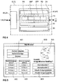
- FIG. 4 shows a figure for a simplified illustration exemplary structure of an IT platform according to the invention (IT) of a module (SM, NOT, MM) or an IT platform (IT2) one Control center (LS) with a network interface (INI, ZNI).
- the Network interface (ZNI, INI) is representative of a first integrated network interface (INI) and a central network interface (ZNI). This network interface also serves (INI, ZNI) for data connection with the respective Communication network (K, IK, EK).
- the IT platform points (IT, IT2) a data processing unit (DV) with means for Execution of software routines such as an operating system (OS), a communication stack (KS), IT service applications (ITD) and applications (AP, AP2).
- OS operating system
- KS communication stack
- IT service applications IT service applications
- AP application
- the operating system (BS) is expediently a multitasking operating system simultaneous execution of several programming tasks, such as. IT service applications (ITD).
- IT service applications ITD
- the communication stack (KS) serves to buffer and manage the parallel executable IT service applications (ITD).
- An IT service application (ITD) can e.g. be a web server (WS). This can advantageously those that can be displayed using a web browser Manage websites (WEB) and call them up in the HTTP protocol e.g. by the control center (LS).
- E-mail program (EMP) as IT service application (ITD) e.g. the Alarm messages (EM) mentioned at the beginning are advantageous in the SMTP protocol to ship.
- DTP file transfer program
- DT Files
- AP AP2
- RD reserve IT service application
- IT IT platform
- SM power supply modules
- AP control application
- LT power section
- SM power supply module
- the control center (LS) can also use an IT platform (IT2) which have the same except for the application (AP, AP2) Components such as the IT platform (IT) of a power supply module (SM).
- IT2 IT platform
- AP application
- AP2 Components such as the IT platform (IT) of a power supply module (SM).
- the application (AP2) is used by Control center (LS) for operating and monitoring the individual decentralized Power supply station (SV).
- the from the power station (SV) queried external station data (BP, EM, DT) can advantageously e.g. on a display (BB) represented and tracked.
- FIG. 5 shows an example shown by a browser Website (WEB) on a display (BB) in a control center for Operating and monitoring the decentralized power supply stations (SV).
- WEB browser Website
- BB display
- SV decentralized power supply station
- A2,3 can then the individual modules (SM, NOT, MM) with regard their status will be queried.
- the parent System parameters and system states can be viewed using the example Query module (AM4) can be queried.
- For central tasks or to query the status of the emergency power system (NOT) or the Batteries (NOT) is a separate query module in the example of FIG. 5 (AM1) is provided.
Landscapes
- Engineering & Computer Science (AREA)
- Power Engineering (AREA)
- Computer Networks & Wireless Communication (AREA)
- Signal Processing (AREA)
- Data Exchanges In Wide-Area Networks (AREA)
- Cable Transmission Systems, Equalization Of Radio And Reduction Of Echo (AREA)
Abstract
Description
- FIG 1 :
- einen beispielhaften Aufbau einer Stromversorgungsstation mit einem Kommunikationsnetz zur datentechnischen Verbindung gemäß der Erfindung,
- FIG 2 :
- einen beispielhaften Aufbau eines Routers als erfindungsgemäße Ausbildung eines Netzknotens des Kommunikationsnetzes,
- FIG 3 :
- einen beispielhaften Aufbau eines modularen Stromversorgungssystems gemäß der Erfindung mit einer Leitstelle und drei dezentralen Stromversorgungsstationen,
- FIG 4 :
- einen beispielhaften Aufbau einer erfindungsgemäßen IT-Plattform mit einem Netzinterface zur datentechnischen Verbindung und Mitteln zur Durchführung von IT-Dienstapplikationen und Applikationen zur Steuerung- und Regelung bzw. zum Bedienen und Beobachten der Stromversorgungsstationen, und
- FIG 5 :
- eine durch einen Browser beispielhaft dargestellte Webseite auf einem Display in einer Leitstelle zum Bedienen und Beobachten der dezentralen Stromversorgungsstationen.
Claims (32)
- Stromversorgungsstation (SV) mit mindestens zwei Stromversorgungsmodulen (SM) zur parallelen Energiespeisung und mindestens einem Kommunikationsnetz (K) auf Basis eines Internet-Datenprotokolls zur datentechnischen Verbindung, an das die Stromversorgungsmodule (SM) angeschlossen sind.
- Stromversorgungsstation (SV) nach Anspruch 1 mit zumindest einer Netzersatzanlage (NOT) zur parallelen Energiespeisung, welche an das zur datentechnischen Verbindung dienende Kommunikationsnetz (K) angeschlossen ist.
- Stromversorgungsstation (SV) nach Anspruch 1 oder 2 mit zumindest einem Messmodul (MM) zumindest zur Erfassung von Messwerten (PD) der Stromversorgungsstation (SV), welche an das zur datentechnischen Verbindung dienende Kommunikationsnetz (K) angeschlossen ist.
- Stromversorgungsstation (SV) nach Anspruch 1 bis 3, wobei das Internet-Datenprotokoll ein TCP/IP-Datenprotokoll ist.
- Stromversorgungsstation (SV) nach Anspruch 1 bis 4 mit integrierten Netzinterfaces (INI,INR,ZNI) zum Anschluss an das Kommunikationsnetz (K).
- Stromversorgungsstation (SV) nach Anspruch 1 bis 5, wobei das Kommunikationsnetz (K) insbesondere zum datentechnischen Austausch von internen Stationsdaten (PD,EM) und externen Stationsdaten (BP,EM,DT) dient.
- Stromversorgungsstation (SV) nach Anspruch 6, wobei die internen Stationsdaten (PD,EM) insbesondere Prozessdaten (PD) und elektronische Meldungen (EM) sind.
- Stromversorgungsstation (SV) nach Anspruch 6, wobei die externen Stationsdaten (BP,EM,DT) insbesondere Betriebsparameter (BP), elektronische Meldungen (EM) und Dateien (DT) sind.
- Stromversorgungsstation (SV) nach Anspruch 1 bis 8 mit einem Netzknoten (NK) zur Aufteilung des Kommunikationsnetzes (K) in ein internes Kommunikationsnetz (IK) und externes Kommunikationsnetz (EK).
- Stromversorgungsstation (SV) nach Anspruch 9, wobei das interne Kommunikationsnetz (IK) ein Intranet ist.
- Stromversorgungsstation (SV) nach Anspruch 9, wobei das externe Kommunikationsnetz (EK) das Internet ist.
- Stromversorgungsstation (SV) nach Anspruch 9, wobei das externe Kommunikationsnetz (EK) das Intranet ist.
- Stromversorgungsstation (SV) nach Anspruch 9 oder 10, wobei das durch den Netzknoten (NK) abgeteilte interne Kommunikationsnetz (IK) insbesondere zum datentechnischen Austausch von internen Stationsdaten (PD,EM) dient.
- Stromversorgungsstation (SV) nach einem der Ansprüche 9, 11 oder 12, wobei das durch den Netzknoten (NK) abgeteilte externe Kommunikationsnetz (EK) insbesondere zum datentechnischen Austausch von externen Stationsdaten (BP,EM,DT) dient.
- Stromversorgungsstation (SV) nach Anspruch 9 bis 14, wobei der Netzknoten (NK) als Router (RT) ausgebildet ist.
- Stromversorgungsstation (SV) nach Anspruch 15, wobei der Router (RT) aufweista) mindestens zwei zweite integrierte Netzinterface (INR) zur Verbindung des internen Kommunikationsnetz (IK) mit dem ersten integrierten Netzinterface (INI) des jeweiligen Stromversorgungsmoduls (SM),b) mindestens ein zweites integriertes Netzinterface (INR) zur Verbindung mit dem externen Kommunikationsnetzwerk (EK), undc) Mittel zur Verbindungsherstellung zwischen den jeweiligen zweiten integrierten Netzinterface (INR).
- Stromversorgungsstation (SV) nach Anspruch 5 bis 16, wobei die jeweiligen ersten integrierten Netzinterface (INI) der Stromversorgungsmodule (SM) in eine IT-Plattform (IT) integriert sind.
- Stromversorgungsstation (SV) nach Anspruch 17, wobei die IT-Plattform (IT) zumindest weiterhin aufweista) eine Datenverarbeitungseinheit (DV) mit einem Betriebssystem (BS),b) IT-Dienstapplikationen (ITD) zur datentechnischen Interaktion mit dem an das erste integrierte Netzinterface (INI) angeschlossene interne Kommunikationsnetz (IK),c) einen Kommunikations-Stack (KS) zur Pufferung und Verwaltung der IT-Dienstapplikationen (ITD), undd) zumindest eine Applikation (AP) zur Steuerung und Regelung zumindest eines Teils der Stromversorgungsstation (SV).
- Stromversorgungsstation (SV) nach Anspruch 17 oder 18, wobei die IT-Plattformen (IT) der Stromversorgungsmodule (SM) identisch ausgebildet sind.
- Stromversorgungsstation (SV) nach Anspruch 18 oder 19, wobei zumindest eine Applikation (AP) einer ersten IT-Plattformen (IT) die Masterfunktion zumindest zur Steuerung und Regelung der Stromversorgungsstation (SV) bildet.
- Stromversorgungsstation (SV) nach Anspruch 20, wobei zumindest eine Applikation (AP) einer verbleibenden IT-Plattform (IT) die Masterfunktion nach Ausfall der ersten IT-Plattform (IT) bildet.
- Stromversorgungsstation (SV) nach Anspruch 18 bis 21, wobei ein Web-Server (WS) als IT-Dienstapplikation (ITD) zur Verwaltung zumindest einer Webseite (WEB) der Stromversorgungsstation (SV) verwendet wird.
- Stromversorgungsstation (SV) nach Anspruch 18 bis 22, wobei ein E-mail-Programm (EMP) als IT-Dienstapplikation (ITD) zum Senden und Empfang von elektronischen Meldungen (EM) verwendet wird.
- Stromversorgungsstation (SV) nach Anspruch 18 bis 23, wobei ein Datei-Transfer-Programm (DTP als IT-Dienstapplikation (ITD) zum Auf- und Abladen von Dateien (DT) verwendet wird.
- Modulares Stromversorgungssystem (MSS) mit zumindest einer dezentralen Stromversorgungsstation (SV) nach einem der Ansprüche 1 bis 24, aufweisenda) zumindest eine zentrale Leitstelle (LS) zum fernsteuerbaren Austausch von externen Stationsdaten (BP,EM,DT) der jeweiligen dezentralen Stromversorgungsstationen (SV), insbesondere von Betriebsparametern (BP), Meldungen (EM) und Dateien (DT), undb) ein Kommunikationsnetz (K) auf Basis eines Internet-Datenprotokolls zur datentechnischen Verbindung der Leitstelle (LS) mit den jeweiligen Stromversorgungsstationen (SV).
- Modulares Stromversorgungssystem (MSS) nach Anspruch 25, wobei die Leitstelle (LS) mittels eines zentralen Netzinterface (ZNI) an das Kommunikationsnetz (K) angeschlossen ist.
- Stromversorgungsstation (SV) nach Anspruch 26, wobei das zentrale integrierte Netzinterface (ZNI) in eine IT-Plattform (IT2) der Leitstelle (LS) integriert ist.
- Stromversorgungsstation (SV) nach Anspruch 27, wobei die IT-Plattform (IT2) der Leitstelle (LS) zumindest weiterhin aufweista) eine Datenverarbeitungseinheit (DV) mit einem Betriebssystem (BS),b) IT-Dienstapplikationen (ITD) zur datentechnischen Interaktion mit dem an das zentrale integrierte Netzinterface (ZNI) angeschlossene externe Kommunikationsnetz (EK),c) einen Kommunikations-Stack (KS) zur Pufferung und Verwaltung der IT-Dienstapplikationen (ITD), undd) zumindest eine Applikation (AP2) zum Bedienen und Beobachten der Stromversorgungsstationen (SV).
- Modulares Stromversorgungssystem (MSS) nach Anspruch 25 bis 28, wobei das Kommunikationsnetz (K) ein externes Kommunikationsnetz (EK) ist.
- Modulares Stromversorgungssystem (MSS) nach Anspruch 29, wobei das externe Kommunikationsnetz (EK) das Internet ist.
- Verwendung einer Stromversorgungsstation (SV) nach einem der Ansprüche 1 bis 24 zur Speisung mindestens einer Telekommunikationsanlage (T) .
- Verwendung eines modularen Stromversorgungssystem (MSS) nach einem der Ansprüche 25 bis 30 zur Speisung mindestens einer Telekommunikationsanlage (T).
Applications Claiming Priority (2)
| Application Number | Priority Date | Filing Date | Title |
|---|---|---|---|
| DE2001116804 DE10116804A1 (de) | 2001-04-04 | 2001-04-04 | Stromversorgungsstation und modulares Stromversorgungssystem zur Speisung mindestens einer Telekommunikationssanlage |
| DE10116804 | 2001-04-04 |
Publications (2)
| Publication Number | Publication Date |
|---|---|
| EP1251645A2 true EP1251645A2 (de) | 2002-10-23 |
| EP1251645A3 EP1251645A3 (de) | 2005-03-16 |
Family
ID=7680372
Family Applications (1)
| Application Number | Title | Priority Date | Filing Date |
|---|---|---|---|
| EP02006948A Withdrawn EP1251645A3 (de) | 2001-04-04 | 2002-03-26 | Stromversorgungsstation und modulares Stromversorgungssystem zur Speisung mindestens einer Telekommunikationsanlage |
Country Status (2)
| Country | Link |
|---|---|
| EP (1) | EP1251645A3 (de) |
| DE (1) | DE10116804A1 (de) |
Families Citing this family (2)
| Publication number | Priority date | Publication date | Assignee | Title |
|---|---|---|---|---|
| DE102004002330A1 (de) * | 2004-01-16 | 2005-08-04 | Abb Patent Gmbh | System zur Datenübertragung in Schaltanlagen |
| DE102004007151B4 (de) * | 2004-02-12 | 2009-01-29 | Siemens Ag | Verfahren und Vorrichtung zur Überwachung und Beeinflussung von Versorgungsmodulen für Verbraucher |
Citations (1)
| Publication number | Priority date | Publication date | Assignee | Title |
|---|---|---|---|---|
| WO1996023377A1 (en) * | 1995-01-27 | 1996-08-01 | Intecom, Incorporated | Multimedia system having central power source and distribution subsystem |
Family Cites Families (1)
| Publication number | Priority date | Publication date | Assignee | Title |
|---|---|---|---|---|
| JPH07115428A (ja) * | 1993-10-20 | 1995-05-02 | Hitachi Ltd | 遠隔電源制御方式 |
-
2001
- 2001-04-04 DE DE2001116804 patent/DE10116804A1/de not_active Ceased
-
2002
- 2002-03-26 EP EP02006948A patent/EP1251645A3/de not_active Withdrawn
Patent Citations (1)
| Publication number | Priority date | Publication date | Assignee | Title |
|---|---|---|---|---|
| WO1996023377A1 (en) * | 1995-01-27 | 1996-08-01 | Intecom, Incorporated | Multimedia system having central power source and distribution subsystem |
Non-Patent Citations (1)
| Title |
|---|
| MARQUET D ET AL: "New power supply optimised for new telecom networks and services" TELECOMMUNICATION ENERGY CONFERENCE, 1999. INTELEC '99. THE 21ST INTERNATIONAL COPENHAGEN, DENMARK 6-9 JUNE 1999, PISCATAWAY, NJ, USA,IEEE, US, 6. Juni 1999 (1999-06-06), Seite 392pp, XP010351377 ISBN: 0-7803-5624-1 * |
Also Published As
| Publication number | Publication date |
|---|---|
| DE10116804A1 (de) | 2002-10-17 |
| EP1251645A3 (de) | 2005-03-16 |
Similar Documents
| Publication | Publication Date | Title |
|---|---|---|
| EP2049960B1 (de) | Verfahren zur inbetriebnahme von mindestens einem feldgerät | |
| AT504120B1 (de) | Wechselrichtersystem, wechselrichter und verfahren zum betreiben von wechselrichtern eines wechselrichtersystems | |
| EP1749340A1 (de) | Solarwechselrichter und photovoltaikanlage mit mehreren solarwechselrichtern | |
| EP2438722B1 (de) | Datenübermittlungsgerät zur fernüberwachung und -steuerung eines verteilten prozesssystems | |
| DE3236812A1 (de) | Fernwirksystem | |
| EP3622357B1 (de) | Steuerungssystem zum steuern von sicherheitskritischen und nichtsicherheitskritischen prozessen mit master-slave-funktionalität | |
| EP2598954A1 (de) | Konfiguration der kommunikationsverbindungen von feldgeräten einer energieautomatisierungsanlage | |
| EP2053476A2 (de) | System zum Betreiben wenigstens eines nichtsicherheitskritischen und wenigstens eines sicherheitskritischen Prozesses | |
| EP1805567B1 (de) | Verfahren und automatisierungssystem zum bedienen und/oder beobachten mindestens eines feldgerätes | |
| EP4191954A1 (de) | Moduleinheit zum verbinden eines datenbusteilnehmers | |
| WO1998005111A1 (de) | Schaltanlage | |
| DE102005009707A1 (de) | Modulares numerisches Steuergerät | |
| EP0192120B1 (de) | Verfahren und Einrichtung zur Datenübertragung in der Fernwirktechnik | |
| EP1999526A1 (de) | Drahtlose feldbus verwaltung | |
| DE69831005T2 (de) | Kreislauf und verfahren zur verwaltung der leistungsverteilung | |
| EP3528065B1 (de) | Verfahren zum überwachen, steuern und kontrollierten herunterfahren von steuer- und/oder computereinheiten | |
| EP2171914B1 (de) | Power management | |
| EP1690390B1 (de) | Verfahren zur übertragung von daten über einen datenbus sowie system und gateway zur durchführung des verfahrens | |
| EP1251645A2 (de) | Stromversorgungsstation und modulares Stromversorgungssystem zur Speisung mindestens einer Telekommunikationsanlage | |
| DE112020000249T5 (de) | Neuzuordnung von reglerphasen innerhalb einer phasenredundanten spannungsregler-vorrichtung | |
| AT505741A1 (de) | Dezentrale energieversorgungseinrichtung für ein modulares, fehlersicheres steuerungssystem | |
| DE19921359C2 (de) | Datenübertragungssystem mit bidirektionaler Datenburstübertragung zwischen einer Zentrale und mindestens einer an einen Bus angeschlossenen Busstation | |
| DE102004007151B4 (de) | Verfahren und Vorrichtung zur Überwachung und Beeinflussung von Versorgungsmodulen für Verbraucher | |
| WO2019034475A1 (de) | Leistungselektronisches system | |
| DE202009016193U1 (de) | Fern-überwachbares Stromversorgungssystem |
Legal Events
| Date | Code | Title | Description |
|---|---|---|---|
| PUAI | Public reference made under article 153(3) epc to a published international application that has entered the european phase |
Free format text: ORIGINAL CODE: 0009012 |
|
| AK | Designated contracting states |
Kind code of ref document: A2 Designated state(s): AT BE CH CY DE DK ES FI FR GB GR IE IT LI LU MC NL PT SE TR |
|
| AX | Request for extension of the european patent |
Free format text: AL;LT;LV;MK;RO;SI |
|
| PUAL | Search report despatched |
Free format text: ORIGINAL CODE: 0009013 |
|
| AK | Designated contracting states |
Kind code of ref document: A3 Designated state(s): AT BE CH CY DE DK ES FI FR GB GR IE IT LI LU MC NL PT SE TR |
|
| AX | Request for extension of the european patent |
Extension state: AL LT LV MK RO SI |
|
| RIC1 | Information provided on ipc code assigned before grant |
Ipc: 7H 04M 19/00 B Ipc: 7H 04B 3/54 A |
|
| 17P | Request for examination filed |
Effective date: 20050404 |
|
| AKX | Designation fees paid |
Designated state(s): AT BE CH CY DE DK ES FI FR GB GR IE IT LI LU MC NL PT SE TR |
|
| 17Q | First examination report despatched |
Effective date: 20090917 |
|
| STAA | Information on the status of an ep patent application or granted ep patent |
Free format text: STATUS: THE APPLICATION IS DEEMED TO BE WITHDRAWN |
|
| 18D | Application deemed to be withdrawn |
Effective date: 20100128 |