EP1251596B2 - Connecteur multipolaire pour les systèmes de contrôle et de réglage - Google Patents
Connecteur multipolaire pour les systèmes de contrôle et de réglage Download PDFInfo
- Publication number
- EP1251596B2 EP1251596B2 EP02008928.0A EP02008928A EP1251596B2 EP 1251596 B2 EP1251596 B2 EP 1251596B2 EP 02008928 A EP02008928 A EP 02008928A EP 1251596 B2 EP1251596 B2 EP 1251596B2
- Authority
- EP
- European Patent Office
- Prior art keywords
- unit
- connecting unit
- pin
- diagnostic
- contact pins
- Prior art date
- Legal status (The legal status is an assumption and is not a legal conclusion. Google has not performed a legal analysis and makes no representation as to the accuracy of the status listed.)
- Expired - Lifetime
Links
Images
Classifications
-
- H—ELECTRICITY
- H01—ELECTRIC ELEMENTS
- H01R—ELECTRICALLY-CONDUCTIVE CONNECTIONS; STRUCTURAL ASSOCIATIONS OF A PLURALITY OF MUTUALLY-INSULATED ELECTRICAL CONNECTING ELEMENTS; COUPLING DEVICES; CURRENT COLLECTORS
- H01R13/00—Details of coupling devices of the kinds covered by groups H01R12/70 or H01R24/00 - H01R33/00
- H01R13/46—Bases; Cases
- H01R13/514—Bases; Cases composed as a modular blocks or assembly, i.e. composed of co-operating parts provided with contact members or holding contact members between them
-
- H—ELECTRICITY
- H01—ELECTRIC ELEMENTS
- H01R—ELECTRICALLY-CONDUCTIVE CONNECTIONS; STRUCTURAL ASSOCIATIONS OF A PLURALITY OF MUTUALLY-INSULATED ELECTRICAL CONNECTING ELEMENTS; COUPLING DEVICES; CURRENT COLLECTORS
- H01R13/00—Details of coupling devices of the kinds covered by groups H01R12/70 or H01R24/00 - H01R33/00
- H01R13/66—Structural association with built-in electrical component
- H01R13/665—Structural association with built-in electrical component with built-in electronic circuit
-
- H—ELECTRICITY
- H01—ELECTRIC ELEMENTS
- H01R—ELECTRICALLY-CONDUCTIVE CONNECTIONS; STRUCTURAL ASSOCIATIONS OF A PLURALITY OF MUTUALLY-INSULATED ELECTRICAL CONNECTING ELEMENTS; COUPLING DEVICES; CURRENT COLLECTORS
- H01R9/00—Structural associations of a plurality of mutually-insulated electrical connecting elements, e.g. terminal strips or terminal blocks; Terminals or binding posts mounted upon a base or in a case; Bases therefor
- H01R9/22—Bases, e.g. strip, block, panel
- H01R9/24—Terminal blocks
- H01R9/2458—Electrical interconnections between terminal blocks
-
- H—ELECTRICITY
- H01—ELECTRIC ELEMENTS
- H01R—ELECTRICALLY-CONDUCTIVE CONNECTIONS; STRUCTURAL ASSOCIATIONS OF A PLURALITY OF MUTUALLY-INSULATED ELECTRICAL CONNECTING ELEMENTS; COUPLING DEVICES; CURRENT COLLECTORS
- H01R9/00—Structural associations of a plurality of mutually-insulated electrical connecting elements, e.g. terminal strips or terminal blocks; Terminals or binding posts mounted upon a base or in a case; Bases therefor
- H01R9/22—Bases, e.g. strip, block, panel
- H01R9/24—Terminal blocks
- H01R9/2491—Terminal blocks structurally associated with plugs or sockets
Definitions
- the invention relates to a multi-pin connector for connecting an input / output unit to a machine control according to the preamble of claim 1.
- a connector is z.
- Modular control systems are in the manufacturing industry for manufacturing equipment, transport equipment or the like. Necessary. They have to be carefully planned and created and, especially when upgrading the production facilities, permit extensions. This is achieved by fixed power and data lines to which an interface card can be connected at any point along its length, which can be connected via input / output modules and I / O units such as actuators, sensors, or the like.
- connection of an actuator to the data bus takes place in a different way than the connection of a sensor.
- a sensor reports signals to the data bus, so it is queried from the data bus.
- An actuator is acted upon via the data bus with a control signal; usually an actuator is actuated by switching an electric current.
- control signals are thus transmitted from the data bus to the actuator.
- the design, planning and installation of the system must therefore be carried out depending on the actuators and sensors used. This is expensive and especially disturbing when exchanging slots during conversion or upgrading the system and actuators must be connected instead of sensors or vice versa.
- an electronic, operated by the terminal unit switch is arranged for free parameterization of a pin of a connector between the pin and a terminal unit.
- the pin is connected to a fieldbus via the electronic connection unit, with the pin optionally being connected as a signal input for a sensor, as a control output for an actuator or as a diagnostic input or diagnostic output.
- the invention has for its object to form a multi-pin connector for connecting an input / output unit to a machine control such that the connection of different input / output units is easily possible.
- the multi-pin connector with four contact pins, a terminal unit and arranged between the terminal and the contact pins switches via the electronic terminal unit connects to the data bus, wherein the same contact pin of the terminal unit can be switched either as a signal input for a sensor or as a control output for an actuator can.
- This electronic conversion is also possible via software directly from the data bus.
- only one type of connector or a module variant is necessary, which simplifies storage, installation and maintenance.
- the pin of the connector is alternatively as a function input or diagnostic input and the pin is to be switched as an output or function input.
- a contact pin as a diagnostic input and / or diagnostic output, so that z. B. a freed pin can be used by the terminal unit as a diagnostic connection.
- an electronic, operated by the terminal unit switch is arranged, which connects the contact pin depending on the type of the connected I / O unit optionally with a signal input module of the terminal unit or with a control output module and / or with a diagnostic module ,
- a free parameterization of the connector or the contact pins of the connector is possible, so that in a simple manner by plugging a sensor to an actuator port and vice versa, the connector of the connected unit can be operated accordingly.
- connection unit must be programmed via the machine control data bus to control the electrical switch according to the connected I / O unit. Therefore, undefined states can be avoided both at start-up of the control and reprogramming to other parameters is possible at any time.
- the diagnostic module can transmit the evaluated data via the fieldbus to a central monitoring unit;
- the diagnostic module is connected to display elements, which are expediently designed as LEDs and give the user the opportunity to spot a faulty input / output unit and initiate countermeasures.
- Occurring error conditions are expedient both signaled on the display unit and transmitted to the data bus. This simultaneous error message on site and to the control center ensures a high level of security.
- the diagnostic module not only checks the connected unit but can also monitor the line connection to the units or interface. If z. B. on an output a signal and turns in response to a current of z. B. less than 3mA, there is a line break, which is displayed as an "open load" state.
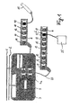
- Fig. 1 represented interface is part of a machine control and is connected via a power line 1 to a live network and connected via a field bus 2 with the central machine control for the exchange of data and control commands.
- a power supply 3 is first connected to the power line 1.
- the power supply unit 3 serves to supply power to individual components to be connected.
- the connection to the fieldbus 2 is achieved via a preferably active interface card 4 having four terminals 4a, 4b, 4c and 4d for individual components such as a plurality of input / output modules 10, 12 or the like.
- the modules 10 consist of an M12 plug connection, while the modules 12 consist of an M8 plug connection 6.
- the modules 10, 12 are fixedly arranged in a holder and connected via a link module 11 and an interface cable 23 to a terminal 4a, 4b, 4c, 4d of the interface card 4.
- Each connector 6 of the input / output modules 10, 12 is provided as a multi-pin connector for connecting an input / output unit such as an actuator 25 or a sensor 15, which in Fig. 1 are indicated schematically.
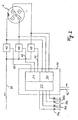
- the contact pins 1, 2, 4 of in Fig. 2 shown connector 6 via an electronic terminal unit 41 and a bus cable 42 are connected to the data bus 2. It is inventively provided that the same contact pin 1, 2 or 4 is to be switched either as a signal input for a sensor or as a control output for an actuator. The same contact pin 1, 2, 4 can also be switched as a diagnostic input and / or diagnostic output.
- pin 2 and pin 4 can be freely parameterized in the case of an M12 plug-in connection, with pin 2 or 4 being connected, for example, as a digital function input with normally open or normally closed functionality, as a diagnostic input or as a digital output.
- a parameterization as analog input and output for voltage and current is useful.
- analog sensors can be used to connect control sensors whose signal voltage or signal current is proportional to a control variable and is, for example, in the range between 0 and 10V or 0 and 20 mA.
- actuators can be controlled as actuators, so that an analog control signal is applied to the output.
- an electronic switch 40 is disposed between each contact pin 1, 2, 4 of the connector 6 and the terminal unit 41, which is preferably designed as an IC.
- the electronic switch 40 is actuated by the terminal unit 41, each individual contact pin 1, 2, 4 depending on the type of the connected I / O unit 15, 25 optionally with a signal input module 30 or - controlled by a control signal output module 31 - with a power supply 33 is to be connected.
- the connecting unit 41 can also connect each of the contact pins 1, 2, 4 with a diagnostic module 32 for fault detection.
- the trained especially as IC electronic switch 40 is to control the fieldbus 2 of the machine control via the bus cable 42, so that a connector 6 of an I / O module 10, 12 can be used differently according to the connected via the connector 6 input / output units , Is about the connector z.
- a bipolar sensor connected, the poles 1 and 2 via the electronic switch 40 and the control / signal lines 43 are connected to the signal input module 30; from the power supply 33, the contact pins 1 and 2 are then disconnected.
- a diagnosis of the connected sensor can be made so that the contact pin 4 is connected via the IC 40 to the diagnostic module 32.
- each pin is assigned a yellow LED 34a, 35a as an OK indicator and a red LED 34b and 35b as an error indicator.
- the terminal unit 41 may be self-detecting, i. h., after connection z. B. a sensor to the connector 6, the terminal unit 41 checks whether a current flows through the connected contact pin 1. If this is the case, the connection is detected as a sensor and the IC 40 is controlled accordingly. A detection of a sensor can also be done by discontinued test signals and incoming electrical feedback.
- the terminal is to be recognized as an output and to control accordingly by the terminal unit 41 via the IC 40.
- the actuators can also be monitored via the diagnostic module 32, so that e.g. for a given control signal, the self-adjusting current is monitored. If it is below a threshold of e.g. 3mA, there is a line break, which is displayed as an "open load" state.
- a creeping occurring overcurrent can be detected with a diagnostic module, so that a kind of advance notice is provided.
- the user will see too high a current warning of a possible failure in the near future, even though the system is still working properly at the time the overcurrent indicator is activated.
- the output currents can be set between limit values in the range from 0 to 2A, preferably set variably.
- the permissible currents can be set as required according to the parameterization so that each pin 1, 2 or 4 can be monitored for the permissible current by the diagnostic module.
- a pre-failure indicator is generated that reports the overload. The user can thus detect an imminent failure and initiate countermeasures.
Claims (5)
- Ensemble composé d'un connecteur multipolaire comprenant quatre broches de contact (1, 2, 3, 4), d'une unité de raccordement (41) et de commutateurs (40) disposés entre l'unité de raccordement (41) et les broches de contact (1, 2, 4) pour le raccordement d'une unité d'entrée sortie telle qu'un actionneur (25), un capteur (15) ou similaire à une commande de machine comprenant un bus de terrain (2) central, un commutateur électronique (40) actionné par l'unité de raccordement (41) étant aménagé entre chacune de ces broches de contact (1, 2, 4) du connecteur (6) et l'unité de raccordement (41) pour le paramétrage libre de ces trois broches de contact (1, 2, 4), de sorte que chacune de ces broches de contact (1, 2, 4) est reliée au câble de bus (42) du bus de terrain (2) par l'intermédiaire de l'unité de raccordement électronique (41), cette même broche de contact (1, 2, 4) étant commutée sélectivement en tant qu'entrée de signal pour un capteur (15), ou en tant que sortie de commande pour un actionneur (25) ou en tant qu'entrée de diagnostic ou sortie de diagnostic, de telle manière qu'un commutateur (40) relie sélectivement chaque broche de contact (1, 2, 4) en fonction du type de l'unité d'entrée sortie (15, 25) raccordée à un module d'entrée de signal (30) de l'unité de raccordement (41) ou à une alimentation en tension (33) ou à un module de diagnostic (32), et l'unité de raccordement (41) doit être programmée par l'intermédiaire du bus de terrain (2) de la commande de machine afin de commander les commutateurs électriques (40) conformément à l'unité d'entrée sortie (15, 25) raccordée.
- Ensemble selon la revendication 1,
caractérisé en ce que le commutateur électronique (40) est un circuit intégré. - Ensemble selon la revendication 1 ou 2,
caractérisé en ce que le module de diagnostic (32) est relié à des éléments d'indication (34, 35) affectés de préférence à une broche. - Ensemble selon la revendication 3,
caractérisé en ce que les éléments d'indication (34, 35) sont des électrodes électroluminescentes. - Ensemble selon l'une quelconque des revendications 1 à 4,
caractérisé en ce que le module de diagnostic (32) surveille des courants de fonctionnement et, dans le cas de dépassement d'une valeur limite, génère une indication d'avertissement et/ou d'erreur.
Priority Applications (2)
| Application Number | Priority Date | Filing Date | Title |
|---|---|---|---|
| EP02008928.0A EP1251596B2 (fr) | 2001-04-20 | 2002-04-22 | Connecteur multipolaire pour les systèmes de contrôle et de réglage |
| DE20220803U DE20220803U1 (de) | 2001-04-20 | 2002-04-22 | Mehrpolige Steckverbindung für Steuerungs- und Automatisierungssysteme |
Applications Claiming Priority (3)
| Application Number | Priority Date | Filing Date | Title |
|---|---|---|---|
| EP01109714A EP1251595B1 (fr) | 2001-04-20 | 2001-04-20 | Installation de contrôle modulaire pour des systèmes de contrôle et de réglage |
| EP01109714 | 2001-04-20 | ||
| EP02008928.0A EP1251596B2 (fr) | 2001-04-20 | 2002-04-22 | Connecteur multipolaire pour les systèmes de contrôle et de réglage |
Publications (3)
| Publication Number | Publication Date |
|---|---|
| EP1251596A1 EP1251596A1 (fr) | 2002-10-23 |
| EP1251596B1 EP1251596B1 (fr) | 2004-06-02 |
| EP1251596B2 true EP1251596B2 (fr) | 2016-01-13 |
Family
ID=26076553
Family Applications (1)
| Application Number | Title | Priority Date | Filing Date |
|---|---|---|---|
| EP02008928.0A Expired - Lifetime EP1251596B2 (fr) | 2001-04-20 | 2002-04-22 | Connecteur multipolaire pour les systèmes de contrôle et de réglage |
Country Status (2)
| Country | Link |
|---|---|
| EP (1) | EP1251596B2 (fr) |
| DE (1) | DE20220803U1 (fr) |
Families Citing this family (1)
| Publication number | Priority date | Publication date | Assignee | Title |
|---|---|---|---|---|
| DE102013108532A1 (de) | 2013-08-07 | 2015-02-12 | Endress + Hauser Gmbh + Co. Kg | Steckverbinder |
Family Cites Families (3)
| Publication number | Priority date | Publication date | Assignee | Title |
|---|---|---|---|---|
| DE2415727C3 (de) * | 1974-04-01 | 1978-06-22 | Brandi Entwicklungsgesellschaft Mbh, 1000 Berlin | Elektrosystem zur Stromversorgung und Fernbedienung elektrischer Geräte |
| JP3311657B2 (ja) * | 1997-10-01 | 2002-08-05 | 矢崎総業株式会社 | 電気接続箱 |
| US6111772A (en) * | 1999-06-29 | 2000-08-29 | Lee; Chiu-Shan | Universal, voltage variable, safety enhanced electric connector |
-
2002
- 2002-04-22 DE DE20220803U patent/DE20220803U1/de not_active Expired - Lifetime
- 2002-04-22 EP EP02008928.0A patent/EP1251596B2/fr not_active Expired - Lifetime
Also Published As
| Publication number | Publication date |
|---|---|
| DE20220803U1 (de) | 2004-04-01 |
| EP1251596B1 (fr) | 2004-06-02 |
| EP1251596A1 (fr) | 2002-10-23 |
Similar Documents
| Publication | Publication Date | Title |
|---|---|---|
| EP0666631B1 (fr) | Système d'alimentation pour bus de secteur | |
| EP3271932B1 (fr) | Commutateur de sécurité pour interrompre une charge électrique sans erreur | |
| DE4214431C2 (de) | Stufenschalter mit Motorantrieb | |
| EP1932007B1 (fr) | Dispositif et procede d'evaluation a securite integree d'un transmetteur de position, en particulier d'un potentiometre | |
| EP3055741B1 (fr) | Dispositif de commande modulaire avec surveillance de charge | |
| DE102006030706A1 (de) | System und Verfahren zur Steuerung von busvernetzten Geräten über einen offenen Feldbus | |
| EP3025318B1 (fr) | Appareil de mesure doté d'une électronique de fonctionnement et de mesure commutable servant à la communication d'un signal de mesure | |
| EP1269274A1 (fr) | Interrupteur de securite et procede pour ajuster un mode de fonctionnement pour interrupteur de securite | |
| EP2498270B1 (fr) | Relais de sécurité et système de communication orienté vers la sécurité | |
| EP2587512B1 (fr) | Commutateur orienté vers la sécurité | |
| EP3491787B1 (fr) | Module série, système modulaire fonctionnel et système de commande de conception modulaire | |
| DE102016110909A1 (de) | Ventilinsel-Basismodul und Ventilinsel | |
| EP1364459B1 (fr) | Dispositif de commutation de securite | |
| EP1251596B2 (fr) | Connecteur multipolaire pour les systèmes de contrôle et de réglage | |
| EP0809361B1 (fr) | Dispositif électronique de commutation et circuit pour la surveillance d'une installation technique | |
| DE102010038459A1 (de) | Sicherheitssystem | |
| DE10261452A1 (de) | Motorsteuerung mit einer Steuereinrichtung und einer Sicherheitsvorrichtung zum sicheren Abschalten eines Motors | |
| EP1533622B1 (fr) | Procédé de détection de court-circuit entre les conducteurs | |
| DE3721065C2 (de) | Einrichtung zum Betrieb eines Stellantriebs | |
| EP2764592B1 (fr) | Module de sélectivité avec signal d'état en série | |
| DE19844185A1 (de) | Busleitungssystem | |
| DE4446707A1 (de) | Verfahren zur Überwachung einer digitalen Ausgabebaugruppe | |
| WO2013110295A1 (fr) | Dispositif d'alimentation, de commande et/ou d'évaluation sécurisées d'appareils de champ dans le domaine de protection contre les explosions | |
| WO2001004710A1 (fr) | Module de commande d'un mecanisme d'entrainement | |
| EP1259970B1 (fr) | Ensemble de commutation sur, ensemble de commande sur et systeme d'ensembles |
Legal Events
| Date | Code | Title | Description |
|---|---|---|---|
| PUAI | Public reference made under article 153(3) epc to a published international application that has entered the european phase |
Free format text: ORIGINAL CODE: 0009012 |
|
| AK | Designated contracting states |
Kind code of ref document: A1 Designated state(s): AT BE CH CY DE DK ES FI FR GB GR IE IT LI LU MC NL PT SE TR |
|
| AX | Request for extension of the european patent |
Free format text: AL;LT;LV;MK;RO;SI |
|
| 17P | Request for examination filed |
Effective date: 20030405 |
|
| AKX | Designation fees paid |
Designated state(s): AT CH DE FR IT LI |
|
| GRAP | Despatch of communication of intention to grant a patent |
Free format text: ORIGINAL CODE: EPIDOSNIGR1 |
|
| GRAS | Grant fee paid |
Free format text: ORIGINAL CODE: EPIDOSNIGR3 |
|
| GRAA | (expected) grant |
Free format text: ORIGINAL CODE: 0009210 |
|
| AK | Designated contracting states |
Kind code of ref document: B1 Designated state(s): AT CH DE FR IT LI |
|
| REG | Reference to a national code |
Ref country code: CH Ref legal event code: EP Ref country code: CH Ref legal event code: NV Representative=s name: ISLER & PEDRAZZINI AG |
|
| REF | Corresponds to: |
Ref document number: 50200491 Country of ref document: DE Date of ref document: 20040708 Kind code of ref document: P |
|
| PLBI | Opposition filed |
Free format text: ORIGINAL CODE: 0009260 |
|
| PLBQ | Unpublished change to opponent data |
Free format text: ORIGINAL CODE: EPIDOS OPPO |
|
| REG | Reference to a national code |
Ref country code: IE Ref legal event code: FG4D Free format text: GERMAN |
|
| 26 | Opposition filed |
Opponent name: WEIDMUELLER INTERFACE GMBH & CO. Effective date: 20040702 |
|
| REG | Reference to a national code |
Ref country code: IE Ref legal event code: FD4D |
|
| ET | Fr: translation filed | ||
| PLAX | Notice of opposition and request to file observation + time limit sent |
Free format text: ORIGINAL CODE: EPIDOSNOBS2 |
|
| PLAF | Information modified related to communication of a notice of opposition and request to file observations + time limit |
Free format text: ORIGINAL CODE: EPIDOSCOBS2 |
|
| PLBB | Reply of patent proprietor to notice(s) of opposition received |
Free format text: ORIGINAL CODE: EPIDOSNOBS3 |
|
| REG | Reference to a national code |
Ref country code: CH Ref legal event code: PCAR Free format text: ISLER & PEDRAZZINI AG;POSTFACH 1772;8027 ZUERICH (CH) |
|
| RDAF | Communication despatched that patent is revoked |
Free format text: ORIGINAL CODE: EPIDOSNREV1 |
|
| APAH | Appeal reference modified |
Free format text: ORIGINAL CODE: EPIDOSCREFNO |
|
| APBM | Appeal reference recorded |
Free format text: ORIGINAL CODE: EPIDOSNREFNO |
|
| APBP | Date of receipt of notice of appeal recorded |
Free format text: ORIGINAL CODE: EPIDOSNNOA2O |
|
| APBQ | Date of receipt of statement of grounds of appeal recorded |
Free format text: ORIGINAL CODE: EPIDOSNNOA3O |
|
| PLBP | Opposition withdrawn |
Free format text: ORIGINAL CODE: 0009264 |
|
| APBY | Invitation to file observations in appeal sent |
Free format text: ORIGINAL CODE: EPIDOSNOBA2O |
|
| APAR | Information on invitation to file observation in appeal modified |
Free format text: ORIGINAL CODE: EPIDOSCOBA2O |
|
| APCA | Receipt of observations in appeal recorded |
Free format text: ORIGINAL CODE: EPIDOSNOBA4O |
|
| APBU | Appeal procedure closed |
Free format text: ORIGINAL CODE: EPIDOSNNOA9O |
|
| PLAY | Examination report in opposition despatched + time limit |
Free format text: ORIGINAL CODE: EPIDOSNORE2 |
|
| PLBC | Reply to examination report in opposition received |
Free format text: ORIGINAL CODE: EPIDOSNORE3 |
|
| REG | Reference to a national code |
Ref country code: FR Ref legal event code: PLFP Year of fee payment: 14 |
|
| PUAH | Patent maintained in amended form |
Free format text: ORIGINAL CODE: 0009272 |
|
| STAA | Information on the status of an ep patent application or granted ep patent |
Free format text: STATUS: PATENT MAINTAINED AS AMENDED |
|
| 27A | Patent maintained in amended form |
Effective date: 20160113 |
|
| AK | Designated contracting states |
Kind code of ref document: B2 Designated state(s): AT CH DE FR IT LI |
|
| REG | Reference to a national code |
Ref country code: DE Ref legal event code: R102 Ref document number: 50200491 Country of ref document: DE |
|
| REG | Reference to a national code |
Ref country code: CH Ref legal event code: AELC |
|
| REG | Reference to a national code |
Ref country code: FR Ref legal event code: PLFP Year of fee payment: 15 |
|
| REG | Reference to a national code |
Ref country code: FR Ref legal event code: PLFP Year of fee payment: 16 |
|
| REG | Reference to a national code |
Ref country code: FR Ref legal event code: PLFP Year of fee payment: 17 |
|
| PGFP | Annual fee paid to national office [announced via postgrant information from national office to epo] |
Ref country code: DE Payment date: 20210420 Year of fee payment: 20 Ref country code: FR Payment date: 20210423 Year of fee payment: 20 Ref country code: IT Payment date: 20210427 Year of fee payment: 20 |
|
| PGFP | Annual fee paid to national office [announced via postgrant information from national office to epo] |
Ref country code: CH Payment date: 20210420 Year of fee payment: 20 Ref country code: AT Payment date: 20210421 Year of fee payment: 20 |
|
| REG | Reference to a national code |
Ref country code: DE Ref legal event code: R071 Ref document number: 50200491 Country of ref document: DE |
|
| REG | Reference to a national code |
Ref country code: CH Ref legal event code: PL |
|
| REG | Reference to a national code |
Ref country code: AT Ref legal event code: MK07 Ref document number: 268508 Country of ref document: AT Kind code of ref document: T Effective date: 20220422 |