EP1251596B2 - Multipolar connector for control and automatic systems - Google Patents
Multipolar connector for control and automatic systems Download PDFInfo
- Publication number
- EP1251596B2 EP1251596B2 EP02008928.0A EP02008928A EP1251596B2 EP 1251596 B2 EP1251596 B2 EP 1251596B2 EP 02008928 A EP02008928 A EP 02008928A EP 1251596 B2 EP1251596 B2 EP 1251596B2
- Authority
- EP
- European Patent Office
- Prior art keywords
- unit
- connecting unit
- pin
- diagnostic
- contact pins
- Prior art date
- Legal status (The legal status is an assumption and is not a legal conclusion. Google has not performed a legal analysis and makes no representation as to the accuracy of the status listed.)
- Expired - Lifetime
Links
Images
Classifications
-
- H—ELECTRICITY
- H01—ELECTRIC ELEMENTS
- H01R—ELECTRICALLY-CONDUCTIVE CONNECTIONS; STRUCTURAL ASSOCIATIONS OF A PLURALITY OF MUTUALLY-INSULATED ELECTRICAL CONNECTING ELEMENTS; COUPLING DEVICES; CURRENT COLLECTORS
- H01R13/00—Details of coupling devices of the kinds covered by groups H01R12/70 or H01R24/00 - H01R33/00
- H01R13/46—Bases; Cases
- H01R13/514—Bases; Cases composed as a modular blocks or assembly, i.e. composed of co-operating parts provided with contact members or holding contact members between them
-
- H—ELECTRICITY
- H01—ELECTRIC ELEMENTS
- H01R—ELECTRICALLY-CONDUCTIVE CONNECTIONS; STRUCTURAL ASSOCIATIONS OF A PLURALITY OF MUTUALLY-INSULATED ELECTRICAL CONNECTING ELEMENTS; COUPLING DEVICES; CURRENT COLLECTORS
- H01R13/00—Details of coupling devices of the kinds covered by groups H01R12/70 or H01R24/00 - H01R33/00
- H01R13/66—Structural association with built-in electrical component
- H01R13/665—Structural association with built-in electrical component with built-in electronic circuit
-
- H—ELECTRICITY
- H01—ELECTRIC ELEMENTS
- H01R—ELECTRICALLY-CONDUCTIVE CONNECTIONS; STRUCTURAL ASSOCIATIONS OF A PLURALITY OF MUTUALLY-INSULATED ELECTRICAL CONNECTING ELEMENTS; COUPLING DEVICES; CURRENT COLLECTORS
- H01R9/00—Structural associations of a plurality of mutually-insulated electrical connecting elements, e.g. terminal strips or terminal blocks; Terminals or binding posts mounted upon a base or in a case; Bases therefor
- H01R9/22—Bases, e.g. strip, block, panel
- H01R9/24—Terminal blocks
- H01R9/2458—Electrical interconnections between terminal blocks
-
- H—ELECTRICITY
- H01—ELECTRIC ELEMENTS
- H01R—ELECTRICALLY-CONDUCTIVE CONNECTIONS; STRUCTURAL ASSOCIATIONS OF A PLURALITY OF MUTUALLY-INSULATED ELECTRICAL CONNECTING ELEMENTS; COUPLING DEVICES; CURRENT COLLECTORS
- H01R9/00—Structural associations of a plurality of mutually-insulated electrical connecting elements, e.g. terminal strips or terminal blocks; Terminals or binding posts mounted upon a base or in a case; Bases therefor
- H01R9/22—Bases, e.g. strip, block, panel
- H01R9/24—Terminal blocks
- H01R9/2491—Terminal blocks structurally associated with plugs or sockets
Definitions
- the invention relates to a multi-pin connector for connecting an input / output unit to a machine control according to the preamble of claim 1.
- a connector is z.
- Modular control systems are in the manufacturing industry for manufacturing equipment, transport equipment or the like. Necessary. They have to be carefully planned and created and, especially when upgrading the production facilities, permit extensions. This is achieved by fixed power and data lines to which an interface card can be connected at any point along its length, which can be connected via input / output modules and I / O units such as actuators, sensors, or the like.
- connection of an actuator to the data bus takes place in a different way than the connection of a sensor.
- a sensor reports signals to the data bus, so it is queried from the data bus.
- An actuator is acted upon via the data bus with a control signal; usually an actuator is actuated by switching an electric current.
- control signals are thus transmitted from the data bus to the actuator.
- the design, planning and installation of the system must therefore be carried out depending on the actuators and sensors used. This is expensive and especially disturbing when exchanging slots during conversion or upgrading the system and actuators must be connected instead of sensors or vice versa.
- an electronic, operated by the terminal unit switch is arranged for free parameterization of a pin of a connector between the pin and a terminal unit.
- the pin is connected to a fieldbus via the electronic connection unit, with the pin optionally being connected as a signal input for a sensor, as a control output for an actuator or as a diagnostic input or diagnostic output.
- the invention has for its object to form a multi-pin connector for connecting an input / output unit to a machine control such that the connection of different input / output units is easily possible.
- the multi-pin connector with four contact pins, a terminal unit and arranged between the terminal and the contact pins switches via the electronic terminal unit connects to the data bus, wherein the same contact pin of the terminal unit can be switched either as a signal input for a sensor or as a control output for an actuator can.
- This electronic conversion is also possible via software directly from the data bus.
- only one type of connector or a module variant is necessary, which simplifies storage, installation and maintenance.
- the pin of the connector is alternatively as a function input or diagnostic input and the pin is to be switched as an output or function input.
- a contact pin as a diagnostic input and / or diagnostic output, so that z. B. a freed pin can be used by the terminal unit as a diagnostic connection.
- an electronic, operated by the terminal unit switch is arranged, which connects the contact pin depending on the type of the connected I / O unit optionally with a signal input module of the terminal unit or with a control output module and / or with a diagnostic module ,
- a free parameterization of the connector or the contact pins of the connector is possible, so that in a simple manner by plugging a sensor to an actuator port and vice versa, the connector of the connected unit can be operated accordingly.
- connection unit must be programmed via the machine control data bus to control the electrical switch according to the connected I / O unit. Therefore, undefined states can be avoided both at start-up of the control and reprogramming to other parameters is possible at any time.
- the diagnostic module can transmit the evaluated data via the fieldbus to a central monitoring unit;
- the diagnostic module is connected to display elements, which are expediently designed as LEDs and give the user the opportunity to spot a faulty input / output unit and initiate countermeasures.
- Occurring error conditions are expedient both signaled on the display unit and transmitted to the data bus. This simultaneous error message on site and to the control center ensures a high level of security.
- the diagnostic module not only checks the connected unit but can also monitor the line connection to the units or interface. If z. B. on an output a signal and turns in response to a current of z. B. less than 3mA, there is a line break, which is displayed as an "open load" state.
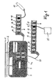
- Fig. 1 represented interface is part of a machine control and is connected via a power line 1 to a live network and connected via a field bus 2 with the central machine control for the exchange of data and control commands.
- a power supply 3 is first connected to the power line 1.
- the power supply unit 3 serves to supply power to individual components to be connected.
- the connection to the fieldbus 2 is achieved via a preferably active interface card 4 having four terminals 4a, 4b, 4c and 4d for individual components such as a plurality of input / output modules 10, 12 or the like.
- the modules 10 consist of an M12 plug connection, while the modules 12 consist of an M8 plug connection 6.
- the modules 10, 12 are fixedly arranged in a holder and connected via a link module 11 and an interface cable 23 to a terminal 4a, 4b, 4c, 4d of the interface card 4.
- Each connector 6 of the input / output modules 10, 12 is provided as a multi-pin connector for connecting an input / output unit such as an actuator 25 or a sensor 15, which in Fig. 1 are indicated schematically.
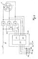
- the contact pins 1, 2, 4 of in Fig. 2 shown connector 6 via an electronic terminal unit 41 and a bus cable 42 are connected to the data bus 2. It is inventively provided that the same contact pin 1, 2 or 4 is to be switched either as a signal input for a sensor or as a control output for an actuator. The same contact pin 1, 2, 4 can also be switched as a diagnostic input and / or diagnostic output.
- pin 2 and pin 4 can be freely parameterized in the case of an M12 plug-in connection, with pin 2 or 4 being connected, for example, as a digital function input with normally open or normally closed functionality, as a diagnostic input or as a digital output.
- a parameterization as analog input and output for voltage and current is useful.
- analog sensors can be used to connect control sensors whose signal voltage or signal current is proportional to a control variable and is, for example, in the range between 0 and 10V or 0 and 20 mA.
- actuators can be controlled as actuators, so that an analog control signal is applied to the output.
- an electronic switch 40 is disposed between each contact pin 1, 2, 4 of the connector 6 and the terminal unit 41, which is preferably designed as an IC.
- the electronic switch 40 is actuated by the terminal unit 41, each individual contact pin 1, 2, 4 depending on the type of the connected I / O unit 15, 25 optionally with a signal input module 30 or - controlled by a control signal output module 31 - with a power supply 33 is to be connected.
- the connecting unit 41 can also connect each of the contact pins 1, 2, 4 with a diagnostic module 32 for fault detection.
- the trained especially as IC electronic switch 40 is to control the fieldbus 2 of the machine control via the bus cable 42, so that a connector 6 of an I / O module 10, 12 can be used differently according to the connected via the connector 6 input / output units , Is about the connector z.
- a bipolar sensor connected, the poles 1 and 2 via the electronic switch 40 and the control / signal lines 43 are connected to the signal input module 30; from the power supply 33, the contact pins 1 and 2 are then disconnected.
- a diagnosis of the connected sensor can be made so that the contact pin 4 is connected via the IC 40 to the diagnostic module 32.
- each pin is assigned a yellow LED 34a, 35a as an OK indicator and a red LED 34b and 35b as an error indicator.
- the terminal unit 41 may be self-detecting, i. h., after connection z. B. a sensor to the connector 6, the terminal unit 41 checks whether a current flows through the connected contact pin 1. If this is the case, the connection is detected as a sensor and the IC 40 is controlled accordingly. A detection of a sensor can also be done by discontinued test signals and incoming electrical feedback.
- the terminal is to be recognized as an output and to control accordingly by the terminal unit 41 via the IC 40.
- the actuators can also be monitored via the diagnostic module 32, so that e.g. for a given control signal, the self-adjusting current is monitored. If it is below a threshold of e.g. 3mA, there is a line break, which is displayed as an "open load" state.
- a creeping occurring overcurrent can be detected with a diagnostic module, so that a kind of advance notice is provided.
- the user will see too high a current warning of a possible failure in the near future, even though the system is still working properly at the time the overcurrent indicator is activated.
- the output currents can be set between limit values in the range from 0 to 2A, preferably set variably.
- the permissible currents can be set as required according to the parameterization so that each pin 1, 2 or 4 can be monitored for the permissible current by the diagnostic module.
- a pre-failure indicator is generated that reports the overload. The user can thus detect an imminent failure and initiate countermeasures.
Landscapes
- Engineering & Computer Science (AREA)
- Microelectronics & Electronic Packaging (AREA)
- Testing And Monitoring For Control Systems (AREA)
- Details Of Connecting Devices For Male And Female Coupling (AREA)
- Programmable Controllers (AREA)
Description
Die Erfindung betrifft eine mehrpolige Steckverbindung zum Anschluß einer Eingabe/Ausgabe-Einheit an einer Maschinensteuerung nach dem Oberbegriff des Anspruchs 1. Eine solche Steckverbindung ist z. B. in dem Dokument
Modulare Steuerungsanlagen sind in der herstellenden Industrie für Fertigungsanlagen, Transportanlagen oder dgl. notwendig. Sie müssen sorgsam geplant und erstellt werden und insbesondere bei Aufrüstung der Fertigungsanlagen Erweiterungen zulassen. Dies wird durch fest verlegte Energie und Datenleitungen erzielt, an die an beliebiger Stelle über ihrer Länge eine Schnittstellenkarte angeschlossen werden kann, über die mittels Eingabe/Ausgabe-Modulen und E/A-Einheiten, wie Aktoren, Sensoren oder dgl. angeschlossen werden.Modular control systems are in the manufacturing industry for manufacturing equipment, transport equipment or the like. Necessary. They have to be carefully planned and created and, especially when upgrading the production facilities, permit extensions. This is achieved by fixed power and data lines to which an interface card can be connected at any point along its length, which can be connected via input / output modules and I / O units such as actuators, sensors, or the like.
Der Anschluß eines Aktors an den Datenbus erfolgt in anderer Weise als der Anschluß eines Sensors. Ein Sensor meldet Signale an den Datenbus, wird also vom Datenbus abgefragt. Ein Aktor hingegen wird über den Datenbus mit einem Steuerungssignal beaufschlagt; meist wird ein Aktor durch Schalten eines elektrischen Stromes betätigt. Bei einem Aktor werden somit Steuerungssignale vom Datenbus an den Aktor übertragen. Die Auslegung, Planung und Installation der Anlage muß daher in Abhängigkeit der eingesetzten Aktoren und Sensoren erfolgen. Dies ist aufwendig und insbesondere dann störend, wenn beim Umbau oder der Aufrüstung der Anlage Steckplätze getauscht werden und anstelle von Sensoren Aktoren angeschlossen werden müssen oder umgekehrt.The connection of an actuator to the data bus takes place in a different way than the connection of a sensor. A sensor reports signals to the data bus, so it is queried from the data bus. An actuator, however, is acted upon via the data bus with a control signal; usually an actuator is actuated by switching an electric current. In the case of an actuator, control signals are thus transmitted from the data bus to the actuator. The design, planning and installation of the system must therefore be carried out depending on the actuators and sensors used. This is expensive and especially disturbing when exchanging slots during conversion or upgrading the system and actuators must be connected instead of sensors or vice versa.
In dem Seminarbericht des Instituts für Werkzeugmaschinen (WZM) und Betriebswissenschaften der technischen Universität München aus dem Jahr 1997 ist zur freien Parametrierung eines Pins einer Steckverbindung zwischen dem Pin und einer Anschlusseinheit ein elektronischer, von der Anschlusseinheit betätigter Schalter angeordnet. Der Pin ist über die elektronische Anschlusseinheit mit einem Feldbus verbunden, wobei der Pin wahlweise als Signaleingang für einen Sensor, als Steuerungsausgang für einen Aktor oder als Diagnoseeingang oder Diagnoseausgang geschaltet ist.In the seminar report of the Institute for Machine Tools (WZM) and Business Administration of the Technical University of Munich from 1997, an electronic, operated by the terminal unit switch is arranged for free parameterization of a pin of a connector between the pin and a terminal unit. The pin is connected to a fieldbus via the electronic connection unit, with the pin optionally being connected as a signal input for a sensor, as a control output for an actuator or as a diagnostic input or diagnostic output.
Der Erfindung liegt die Aufgabe zugrunde, eine mehrpolige Steckverbindung zum Anschluß einer Eingabe/Ausgabe-Einheit an einer Maschinensteuerung derart auszubilden, daß der Anschluß unterschiedlicher Eingabe/Ausgabe-Einheiten einfach möglich ist.The invention has for its object to form a multi-pin connector for connecting an input / output unit to a machine control such that the connection of different input / output units is easily possible.
Die Aufgabe wird erfindungsgemäß nach den Merkmalen des Anspruchs 1 gelöst.The object is achieved according to the features of claim 1.
Die mehrpolige Steckverbindung mit vier Kontaktpins, einer Anschlußeinheit und zwischen der Anschlußeinheit und den Kontaktpins angeordneten Schaltern stellt über die elektronische Anschlußeinheit die Verbindung mit dem Datenbus her, wobei derselbe Kontaktpin von der Anschlußeinheit wahlweise als Signaleingang für einen Sensor oder als Steuerungsausgang für einen Aktor geschaltet werden kann. Dies bedeutet, daß unabhängig von der angeschlossenen Eingabe/Ausgabe-Einheit die körperliche Ausbildung der Steckverbindung gleich bleibt und die Umstellung von einem Aktoranschluß auf einen Sensoranschluß elektronisch erfolgt. Diese elektronische Umstellung ist per Software auch unmittelbar vom Datenbus aus möglich. Somit ist nur eine Bauform einer Steckverbindung bzw. einer Modulvariante notwendig, was die Lagerhaltung, die Montage und die Wartung vereinfacht.The multi-pin connector with four contact pins, a terminal unit and arranged between the terminal and the contact pins switches via the electronic terminal unit connects to the data bus, wherein the same contact pin of the terminal unit can be switched either as a signal input for a sensor or as a control output for an actuator can. This means that regardless of the connected input / output unit, the physical training of the connector remains the same and the change from an actuator port to a sensor port is done electronically. This electronic conversion is also possible via software directly from the data bus. Thus, only one type of connector or a module variant is necessary, which simplifies storage, installation and maintenance.
Der Pin der Steckverbindung ist alternativ als Funktionseingang oder Diagnoseeingang und der Pin ist als Ausgang oder Funktionseingang zu schalten.The pin of the connector is alternatively as a function input or diagnostic input and the pin is to be switched as an output or function input.
Ferner ist vorgesehen, einen Kontaktpin auch als Diagnoseeingang und/oder Diagnoseausgang zu schalten, so daß z. B. ein freiwerdender Pin von der Anschlußeinheit als Diagnoseanschluß genutzt werden kann.It is further provided to switch a contact pin as a diagnostic input and / or diagnostic output, so that z. B. a freed pin can be used by the terminal unit as a diagnostic connection.
Zwischen einem Kontaktpin der Steckverbindung und der Anschlußeinheit ist ein elektronischer, von der Anschlußeinheit betätigter Schalter angeordnet, der den Kontaktpin in Abhängigkeit des Typs der angeschlossenen E/A-Einheit wahlweise mit einem Signaleingangsmodul der Anschlußeinheit oder mit einem Steuerungsausgangsmodul und/oder mit einem Diagnosemodul verbindet. Über den von der elektronischen Anschlußeinheit gesteuerten Schalter ist somit eine freie Parametrierbarkeit der Steckverbindung bzw. der Kontaktpins der Steckverbindung möglich, so daß in einfacher Weise durch Umstecken eines Sensors auf einen Aktoranschluß und umgekehrt die Steckverbindung der angeschlossenen Einheit entsprechend betrieben werden kann.Between a contact pin of the connector and the terminal unit, an electronic, operated by the terminal unit switch is arranged, which connects the contact pin depending on the type of the connected I / O unit optionally with a signal input module of the terminal unit or with a control output module and / or with a diagnostic module , About the controlled by the electronic terminal unit switch thus a free parameterization of the connector or the contact pins of the connector is possible, so that in a simple manner by plugging a sensor to an actuator port and vice versa, the connector of the connected unit can be operated accordingly.
Die Anschlußeinheit ist über den Datenbus der Maschinensteuerung zu programmieren, um den elektrischen Schalter entsprechend der angeschlossenen E/A-Einheit anzusteuern. Daher können sowohl beim Hochfahren der Steuerung undefinierte Zustände vermieden werden, und es ist jederzeit eine Umprogrammierung auf andere Parameter möglich.The connection unit must be programmed via the machine control data bus to control the electrical switch according to the connected I / O unit. Therefore, undefined states can be avoided both at start-up of the control and reprogramming to other parameters is possible at any time.
Das Diagnosemodul kann die ausgewerteten Daten über den Feldbus einer zentralen Überwachungseinheit übermitteln; vorteilhaft ist das Diagnosemodul mit Anzeigeelementen verbunden, die zweckmäßig als LED's ausgeführt sind und vor Ort dem Benutzer die Möglichkeit geben, eine fehlerhafte Eingabe/Ausgabe-Einheit zu erkennen und Gegenmaßnahmen einzuleiten. Auftretende Fehlerzustände werden zweckmäßig sowohl an der Anzeigeeinheit signalisiert als auch auf den Datenbus übertragen. Diese gleichzeitige Fehlermeldung vor Ort und an die Zentrale gewährleistet eine hohe Sicherheit. Das Diagnosemodul überprüft nicht nur die angeschlossene Einheit, sondern kann auch die Leitungsverbindung zu den Einheiten bzw. zur Schnittstelle überwachen. Wird z. B. auf einen Ausgang ein Signal aufgegeben und stellt sich als Reaktion ein Strom von z. B. weniger als 3mA ein, liegt ein Leitungsbruch vor, der als "open load"-Zustand angezeigt wird.The diagnostic module can transmit the evaluated data via the fieldbus to a central monitoring unit; Advantageously, the diagnostic module is connected to display elements, which are expediently designed as LEDs and give the user the opportunity to spot a faulty input / output unit and initiate countermeasures. Occurring error conditions are expedient both signaled on the display unit and transmitted to the data bus. This simultaneous error message on site and to the control center ensures a high level of security. The diagnostic module not only checks the connected unit but can also monitor the line connection to the units or interface. If z. B. on an output a signal and turns in response to a current of z. B. less than 3mA, there is a line break, which is displayed as an "open load" state.
Weitere Merkmale der Erfindung ergeben sich aus den weiteren Ansprüchen, der Beschreibung und der Zeichnung, in der ein Ausführungsbeispiel der Erfindung schematisch dargestellt ist. Es zeigen:
- Fig. 1
- in schematischer Darstellung eine Schnittstelle einer Maschinensteuerung mit einem zentralen Datenbus,
- Fig. 2
- in schematischer Darstellung einen Prinzipschaltplan für die Beschaltung von frei parametrierbaren Kontaktpins.
- Fig. 1
- a schematic representation of an interface of a machine control with a central data bus,
- Fig. 2
- a schematic diagram of a circuit diagram for the wiring of freely configurable contact pins.
Die in
An einem beliebigen Punkt der Energieleitung 1 und des Feldbus 2 kann über die Schnittstelle die Verbindung zu einer Fertigungsanlage, einer Maschine oder dgl. aufgebaut werden. Hierfür wird zunächst ein Netzteil 3 mit der Energieleitung 1 verbunden. Das Netzteil 3 dient der Spannungsversorgung anzuschließender Einzelkomponenten. Die Verbindung mit dem Feldbus 2 wird über eine vorzugsweise aktive Schnittstellenkarte 4 erreicht, welche vier Anschlüsse 4a, 4b, 4c und 4d für Einzelkomponenten wie eine Vielzahl von Eingabe-/Ausgabemodulen 10, 12 oder dgl. aufweist.At any point of the power line 1 and the
Die Module 10 bestehen aus einer M12 Steckverbindung, während die Module 12 aus einer M8 Steckverbindung 6 bestehen.The
Die Module 10, 12 werden in einem Halter ortsfest angeordnet und über ein Linkmodul 11 und ein Schnittstellenkabel 23 mit einem Anschluß 4a, 4b, 4c, 4d der Schnittstellenkarte 4 verbunden.The
Jede Steckverbindung 6 der Eingabe-/Ausgabemodule 10, 12 ist als mehrpolige Steckverbindung zum Anschluß einer Eingabe/Ausgabe-Einheit wie eines Aktors 25 oder eines Sensors 15 vorgesehen, die in
Zur freien Parametrierung eines Kontaktpins 1, 2 oder 4 ist zwischen jedem Kontaktpin 1, 2, 4 der Steckverbindung 6 und der Anschlußeinheit 41 ein elektronischer Schalter 40 angeordnet, der bevorzugt als IC ausgebildet ist. Der elektronische Schalter 40 ist von der Anschlußeinheit 41 betätigt, wobei jeder einzelne Kontaktpin 1, 2, 4 in Abhängigkeit des Typs der angeschlossenen E/A-Einheit 15, 25 wahlweise mit einem Signaleingangsmodul 30 oder - von einem Steuersignal-Ausgangsmodul 31 gesteuert - mit einer Spannungsversorgung 33 zu verbinden ist. Die Anschlußeinheit 41 kann jeden der Kontaktpins 1, 2, 4 auch mit einem Diagnosemodul 32 zur Fehlererkennung verbinden.For free parameterization of a
Der insbesondere als IC ausgebildete elektronische Schalter 40 ist über das Buskabel 42 vom Feldbus 2 der Maschinensteuerung anzusteuern, so daß eine Steckverbindung 6 eines E/A-Moduls 10, 12 entsprechend den über die Steckverbindung 6 angeschlossenen Eingabe/Ausgabe-Einheiten unterschiedlich genutzt werden kann. Wird über die Steckverbindung z. B. ein zweipoliger Sensor angeschlossen, können die Pole 1 und 2 über die elektronischen Schalter 40 und die Steuer/Signalleiten 43 mit dem Signaleingangsmodul 30 verbunden werden; von der Spannungsversorgung 33 sind die Kontaktpins 1 und 2 dann abgekoppelt. Über den noch freien Kontaktpin 4 kann eine Diagnose des angeschlossenen Sensors vorgenommen werden, so daß der Kontaktpin 4 über das IC 40 mit dem Diagnosemodul 32 verbunden wird. Über das Diagnosemodul werden LED's 34a, 34b, 35a, 35b angesteuert, welche den jeweiligen Zustand der Leitungen oder des Sensors anzeigen und einen Fehler z. B. auf Pin 2 oder 4 sofort anzeigen. So sind jedem Pin eine gelbe LED 34a, 35a als OK-Anzeige und eine rote LED 34b und 35b als Fehleranzeige zugeordnet.The trained especially as IC
Die Anschlußeinheit 41 kann selbstdedektierend sein, d. h., nach Anschluß z. B. eines Sensors an die Steckverbindung 6 prüft die Anschlußeinheit 41, ob durch den angeschlossenen Kontaktpin 1 ein Strom fließt. Ist dies der Fall, wird der Anschluß als Sensor erkannt und das IC 40 entsprechend angesteuert. Eine Erkennung eines Sensors kann auch durch aufgegebene Prüfsignale und darauf eingehende elektrische Rückmeldungen erfolgen.The
Ist ein Aktor an die Steckverbindung 6 angeschlossen, liegen andere elektrische Verhältnisse vor als bei einem Sensor, so daß der Anschluß als Ausgang zu erkennen und entsprechend von der Anschlußeinheit 41 über das IC 40 anzusteuern ist. Auch die Aktoren können über das Diagnosemodul 32 überwacht werden, so daß z.B. bei einem aufgegebenen Steuersignal der sich einstellende Strom überwacht wird. Liegt dieser unter einem Grenzwert von z.B. 3mA, liegt ein Leitungsbruch vor, der als "open load"-Zustand angezeigt wird.If an actuator connected to the
Mit einem Diagnosemodul kann insbesondere ein auch schleichend auftretender überstrom festgestellt werden, so daß eine Art Vorausfallanzeige geschaffen ist. Dem Benutzer wird ein zu hoher Strom angezeigt, der vor einem in naher Zukunft möglichen Ausfall warnt, obwohl die Anlage zum Zeitpunkt der aktivierten Überstromanzeige noch fehlerfrei arbeitet. Die Ausgangsströme können bei vorteilhaft digitalen Ausgängen zwischen Grenzwerten im Bereich von 0 bis 2A eingestellt, vorzugsweise variabel eingestellt werden. Die zulässigen Ströme können so entsprechend der Parametrierung wahlweise eingestellt werden, so daß durch das Diagnosemodul jeder Pin 1, 2 oder 4 auf den zulässigen Strom überwacht werden kann. Bei einem fertiggestellten Überstrom zwischen 100% und 120% wird eine Vorausfallanzeige generiert, die die überlast meldet. Der Benutzer kann so einen bevorstehenden Ausfall erkennen und Gegenmaßnahmen einleiten.In particular, a creeping occurring overcurrent can be detected with a diagnostic module, so that a kind of advance notice is provided. The user will see too high a current warning of a possible failure in the near future, even though the system is still working properly at the time the overcurrent indicator is activated. With advantageous digital outputs, the output currents can be set between limit values in the range from 0 to 2A, preferably set variably. The permissible currents can be set as required according to the parameterization so that each
Claims (5)
- Arrangement of a multipole plug-and-socket connector comprising four contact pins (1, 2, 3, 4), a connecting unit (41) and switches (40) located between the connecting unit (41) and the contact pins (1, 2, 4) for connecting an I/O unit such as an actuator (25), a sensor (15) or the like to a machine control with a central field bus (2), wherein an electronic switch (40) actuated by the connecting unit (41) is arranged between each of the three contact pins (1, 2, 4) of the plug-and-socket connector (6) and the connecting unit (41) for the free parameterisation of these three contact pins (1, 2, 4), so that each of these contact pins (1, 2, 4) is connected to the bus cable (42) of the field bus (2) via the electronic connecting unit (41), wherein one and the same contact pin (1, 2, 4) is optionally connected as a signal input for a sensor (15) or as a control output for an actuator (25) or as a diagnostic input or a diagnostic output in such a way that a switch (40) connects each contact pin (1, 2, 4), depending on the type of the connected I/O unit (15, 25), optionally to a signal input module (30) of the connecting unit (41) or to a voltage supply (33) or to a diagnostic module (32), and wherein the connecting unit (41) can be programmed via the field bus (2) of the machine control for selecting the electric switches (40) in accordance with the connected I/O unit (15, 25).
- Arrangement according to claim 1,
characterised in that the electronic switch (40) is an IC. - Arrangement according to claim 1 or 2,
characterised in that the diagnostic module (32) is connected to indicating elements (34, 35), which are preferably assigned to a pin. - Arrangement according to claim 3,
characterised in that the indicating elements (34, 35) are LEDs. - Arrangement according to any of claims 1 to 4,
characterised in that the diagnostic module (32) monitors operating currents and generates a pre-failure indication and/or a fault indication if a limit value is exceeded.
Priority Applications (2)
| Application Number | Priority Date | Filing Date | Title |
|---|---|---|---|
| DE20220803U DE20220803U1 (en) | 2001-04-20 | 2002-04-22 | Multi-pin connector for control and automation systems |
| EP02008928.0A EP1251596B2 (en) | 2001-04-20 | 2002-04-22 | Multipolar connector for control and automatic systems |
Applications Claiming Priority (3)
| Application Number | Priority Date | Filing Date | Title |
|---|---|---|---|
| EP01109714 | 2001-04-20 | ||
| EP01109714A EP1251595B1 (en) | 2001-04-20 | 2001-04-20 | Modular control apparatus for control and automatic systems |
| EP02008928.0A EP1251596B2 (en) | 2001-04-20 | 2002-04-22 | Multipolar connector for control and automatic systems |
Publications (3)
| Publication Number | Publication Date |
|---|---|
| EP1251596A1 EP1251596A1 (en) | 2002-10-23 |
| EP1251596B1 EP1251596B1 (en) | 2004-06-02 |
| EP1251596B2 true EP1251596B2 (en) | 2016-01-13 |
Family
ID=26076553
Family Applications (1)
| Application Number | Title | Priority Date | Filing Date |
|---|---|---|---|
| EP02008928.0A Expired - Lifetime EP1251596B2 (en) | 2001-04-20 | 2002-04-22 | Multipolar connector for control and automatic systems |
Country Status (2)
| Country | Link |
|---|---|
| EP (1) | EP1251596B2 (en) |
| DE (1) | DE20220803U1 (en) |
Families Citing this family (1)
| Publication number | Priority date | Publication date | Assignee | Title |
|---|---|---|---|---|
| DE102013108532A1 (en) * | 2013-08-07 | 2015-02-12 | Endress + Hauser Gmbh + Co. Kg | Connectors |
Family Cites Families (3)
| Publication number | Priority date | Publication date | Assignee | Title |
|---|---|---|---|---|
| DE2415727C3 (en) * | 1974-04-01 | 1978-06-22 | Brandi Entwicklungsgesellschaft Mbh, 1000 Berlin | Electrical system for the power supply and remote control of electrical devices |
| JP3311657B2 (en) * | 1997-10-01 | 2002-08-05 | 矢崎総業株式会社 | Electrical junction box |
| US6111772A (en) * | 1999-06-29 | 2000-08-29 | Lee; Chiu-Shan | Universal, voltage variable, safety enhanced electric connector |
-
2002
- 2002-04-22 DE DE20220803U patent/DE20220803U1/en not_active Expired - Lifetime
- 2002-04-22 EP EP02008928.0A patent/EP1251596B2/en not_active Expired - Lifetime
Also Published As
| Publication number | Publication date |
|---|---|
| EP1251596A1 (en) | 2002-10-23 |
| DE20220803U1 (en) | 2004-04-01 |
| EP1251596B1 (en) | 2004-06-02 |
Similar Documents
| Publication | Publication Date | Title |
|---|---|---|
| EP3271932B1 (en) | Safety switching device for fail-safe disconnecting of an electrical load | |
| EP0666631B1 (en) | Field bus power supply system | |
| DE4214431C2 (en) | Step switch with motor drive | |
| EP1932007B1 (en) | Process and device for the fail-safe evaluation of a position indicator, in particular a potentiometer | |
| EP3055741B1 (en) | Modular control apparatus with load monitoring | |
| DE102006030706A1 (en) | Bus-linked device e.g. circuit breaker, controlling system, has bus subscribers formed as actuators, where each actuator loops primary voltage and auxiliary voltage to successive actuator and has display for its operation condition | |
| EP3025318B1 (en) | Measuring instrument having a switchable measuring and operating electronics system for transmitting a measurement signal | |
| EP1269274A1 (en) | Safety switching unit and method for setting an operational mode of a safety switching unit | |
| EP2498270B1 (en) | Security relay and security-oriented communication system | |
| EP2587512B1 (en) | Safety-oriented switching device | |
| DE102016110909A1 (en) | Valve terminal base module and valve terminal | |
| EP1364459B1 (en) | Safety switch device | |
| EP1251596B2 (en) | Multipolar connector for control and automatic systems | |
| EP0809361B1 (en) | Electronic switching device and circuit arrangement for monitoring a technical installation | |
| DE102010038459A1 (en) | Safety system, has safety module comprising system interface for direct contacting and communication with group protection unit, and load branch comprising another system interface for direct communication with safety module | |
| DE10261452A1 (en) | Engine control with a control device and a safety device for safely switching off an engine | |
| EP1533622B1 (en) | Method for detecting short circuit between conductors | |
| DE3721065C2 (en) | Device for operating an actuator | |
| EP2764592B1 (en) | Selectivity module with serial status signal | |
| DE19844185A1 (en) | Bus line system, especially for controlling compact hydraulic drives as subscribers, has controller with external connection for connected subscriber with same characteristics as ring line | |
| DE4446707A1 (en) | Monitoring method for hierarchical process control system digital output module | |
| WO2013110295A1 (en) | Apparatus for the intrinsically safe supplying, triggering, and/or evaluation of field devices in the explosion-proof realm | |
| WO2001004710A1 (en) | Module for controlling a drive | |
| EP1259970B1 (en) | Secure circuit subassembly, secure control subassembly and a subassembly system | |
| DE10126177A1 (en) | Circuit for monitoring electric load has switching device that opens on reaching or exceeding defined operating characteristic value placed in memory when initializing device |
Legal Events
| Date | Code | Title | Description |
|---|---|---|---|
| PUAI | Public reference made under article 153(3) epc to a published international application that has entered the european phase |
Free format text: ORIGINAL CODE: 0009012 |
|
| AK | Designated contracting states |
Kind code of ref document: A1 Designated state(s): AT BE CH CY DE DK ES FI FR GB GR IE IT LI LU MC NL PT SE TR |
|
| AX | Request for extension of the european patent |
Free format text: AL;LT;LV;MK;RO;SI |
|
| 17P | Request for examination filed |
Effective date: 20030405 |
|
| AKX | Designation fees paid |
Designated state(s): AT CH DE FR IT LI |
|
| GRAP | Despatch of communication of intention to grant a patent |
Free format text: ORIGINAL CODE: EPIDOSNIGR1 |
|
| GRAS | Grant fee paid |
Free format text: ORIGINAL CODE: EPIDOSNIGR3 |
|
| GRAA | (expected) grant |
Free format text: ORIGINAL CODE: 0009210 |
|
| AK | Designated contracting states |
Kind code of ref document: B1 Designated state(s): AT CH DE FR IT LI |
|
| REG | Reference to a national code |
Ref country code: CH Ref legal event code: EP Ref country code: CH Ref legal event code: NV Representative=s name: ISLER & PEDRAZZINI AG |
|
| REF | Corresponds to: |
Ref document number: 50200491 Country of ref document: DE Date of ref document: 20040708 Kind code of ref document: P |
|
| PLBI | Opposition filed |
Free format text: ORIGINAL CODE: 0009260 |
|
| PLBQ | Unpublished change to opponent data |
Free format text: ORIGINAL CODE: EPIDOS OPPO |
|
| REG | Reference to a national code |
Ref country code: IE Ref legal event code: FG4D Free format text: GERMAN |
|
| 26 | Opposition filed |
Opponent name: WEIDMUELLER INTERFACE GMBH & CO. Effective date: 20040702 |
|
| REG | Reference to a national code |
Ref country code: IE Ref legal event code: FD4D |
|
| ET | Fr: translation filed | ||
| PLAX | Notice of opposition and request to file observation + time limit sent |
Free format text: ORIGINAL CODE: EPIDOSNOBS2 |
|
| PLAF | Information modified related to communication of a notice of opposition and request to file observations + time limit |
Free format text: ORIGINAL CODE: EPIDOSCOBS2 |
|
| PLBB | Reply of patent proprietor to notice(s) of opposition received |
Free format text: ORIGINAL CODE: EPIDOSNOBS3 |
|
| REG | Reference to a national code |
Ref country code: CH Ref legal event code: PCAR Free format text: ISLER & PEDRAZZINI AG;POSTFACH 1772;8027 ZUERICH (CH) |
|
| RDAF | Communication despatched that patent is revoked |
Free format text: ORIGINAL CODE: EPIDOSNREV1 |
|
| APAH | Appeal reference modified |
Free format text: ORIGINAL CODE: EPIDOSCREFNO |
|
| APBM | Appeal reference recorded |
Free format text: ORIGINAL CODE: EPIDOSNREFNO |
|
| APBP | Date of receipt of notice of appeal recorded |
Free format text: ORIGINAL CODE: EPIDOSNNOA2O |
|
| APBQ | Date of receipt of statement of grounds of appeal recorded |
Free format text: ORIGINAL CODE: EPIDOSNNOA3O |
|
| PLBP | Opposition withdrawn |
Free format text: ORIGINAL CODE: 0009264 |
|
| APBY | Invitation to file observations in appeal sent |
Free format text: ORIGINAL CODE: EPIDOSNOBA2O |
|
| APAR | Information on invitation to file observation in appeal modified |
Free format text: ORIGINAL CODE: EPIDOSCOBA2O |
|
| APCA | Receipt of observations in appeal recorded |
Free format text: ORIGINAL CODE: EPIDOSNOBA4O |
|
| APBU | Appeal procedure closed |
Free format text: ORIGINAL CODE: EPIDOSNNOA9O |
|
| PLAY | Examination report in opposition despatched + time limit |
Free format text: ORIGINAL CODE: EPIDOSNORE2 |
|
| PLBC | Reply to examination report in opposition received |
Free format text: ORIGINAL CODE: EPIDOSNORE3 |
|
| REG | Reference to a national code |
Ref country code: FR Ref legal event code: PLFP Year of fee payment: 14 |
|
| PUAH | Patent maintained in amended form |
Free format text: ORIGINAL CODE: 0009272 |
|
| STAA | Information on the status of an ep patent application or granted ep patent |
Free format text: STATUS: PATENT MAINTAINED AS AMENDED |
|
| 27A | Patent maintained in amended form |
Effective date: 20160113 |
|
| AK | Designated contracting states |
Kind code of ref document: B2 Designated state(s): AT CH DE FR IT LI |
|
| REG | Reference to a national code |
Ref country code: DE Ref legal event code: R102 Ref document number: 50200491 Country of ref document: DE |
|
| REG | Reference to a national code |
Ref country code: CH Ref legal event code: AELC |
|
| REG | Reference to a national code |
Ref country code: FR Ref legal event code: PLFP Year of fee payment: 15 |
|
| REG | Reference to a national code |
Ref country code: FR Ref legal event code: PLFP Year of fee payment: 16 |
|
| REG | Reference to a national code |
Ref country code: FR Ref legal event code: PLFP Year of fee payment: 17 |
|
| PGFP | Annual fee paid to national office [announced via postgrant information from national office to epo] |
Ref country code: DE Payment date: 20210420 Year of fee payment: 20 Ref country code: FR Payment date: 20210423 Year of fee payment: 20 Ref country code: IT Payment date: 20210427 Year of fee payment: 20 |
|
| PGFP | Annual fee paid to national office [announced via postgrant information from national office to epo] |
Ref country code: CH Payment date: 20210420 Year of fee payment: 20 Ref country code: AT Payment date: 20210421 Year of fee payment: 20 |
|
| REG | Reference to a national code |
Ref country code: DE Ref legal event code: R071 Ref document number: 50200491 Country of ref document: DE |
|
| REG | Reference to a national code |
Ref country code: CH Ref legal event code: PL |
|
| REG | Reference to a national code |
Ref country code: AT Ref legal event code: MK07 Ref document number: 268508 Country of ref document: AT Kind code of ref document: T Effective date: 20220422 |