EP1250838A2 - Dispositif pour la distribution de nourriture à des animaux - Google Patents
Dispositif pour la distribution de nourriture à des animaux Download PDFInfo
- Publication number
- EP1250838A2 EP1250838A2 EP02076475A EP02076475A EP1250838A2 EP 1250838 A2 EP1250838 A2 EP 1250838A2 EP 02076475 A EP02076475 A EP 02076475A EP 02076475 A EP02076475 A EP 02076475A EP 1250838 A2 EP1250838 A2 EP 1250838A2
- Authority
- EP
- European Patent Office
- Prior art keywords
- animal
- feeding
- feed
- bottom portion
- conveyor
- Prior art date
- Legal status (The legal status is an assumption and is not a legal conclusion. Google has not performed a legal analysis and makes no representation as to the accuracy of the status listed.)
- Withdrawn
Links
- 241001465754 Metazoa Species 0.000 title claims abstract description 118
- 238000005192 partition Methods 0.000 claims description 20
- 238000005303 weighing Methods 0.000 claims description 17
- 241000283690 Bos taurus Species 0.000 claims description 7
- 238000005259 measurement Methods 0.000 claims description 4
- 230000015572 biosynthetic process Effects 0.000 claims description 3
- 238000009833 condensation Methods 0.000 claims description 3
- 230000005494 condensation Effects 0.000 claims description 3
- 238000001816 cooling Methods 0.000 claims description 3
- 229910001220 stainless steel Inorganic materials 0.000 claims description 3
- 239000010935 stainless steel Substances 0.000 claims description 3
- 235000013365 dairy product Nutrition 0.000 description 8
- 239000000203 mixture Substances 0.000 description 4
- 230000008901 benefit Effects 0.000 description 3
- 238000010276 construction Methods 0.000 description 3
- 235000021050 feed intake Nutrition 0.000 description 3
- 230000006870 function Effects 0.000 description 3
- 230000007423 decrease Effects 0.000 description 2
- 230000035622 drinking Effects 0.000 description 2
- 230000007246 mechanism Effects 0.000 description 2
- 230000000050 nutritive effect Effects 0.000 description 2
- 241000238631 Hexapoda Species 0.000 description 1
- 241000699670 Mus sp. Species 0.000 description 1
- 238000004378 air conditioning Methods 0.000 description 1
- 244000309466 calf Species 0.000 description 1
- 230000020595 eating behavior Effects 0.000 description 1
- 230000007613 environmental effect Effects 0.000 description 1
- 230000036541 health Effects 0.000 description 1
- 238000010438 heat treatment Methods 0.000 description 1
- 239000004615 ingredient Substances 0.000 description 1
- 238000009434 installation Methods 0.000 description 1
- 239000000463 material Substances 0.000 description 1
- 239000008267 milk Substances 0.000 description 1
- 235000013336 milk Nutrition 0.000 description 1
- 210000004080 milk Anatomy 0.000 description 1
- 238000012986 modification Methods 0.000 description 1
- 230000004048 modification Effects 0.000 description 1
- 230000035807 sensation Effects 0.000 description 1
- 239000013589 supplement Substances 0.000 description 1
- 229920002994 synthetic fiber Polymers 0.000 description 1
Images


Classifications
-
- A—HUMAN NECESSITIES
- A01—AGRICULTURE; FORESTRY; ANIMAL HUSBANDRY; HUNTING; TRAPPING; FISHING
- A01K—ANIMAL HUSBANDRY; AVICULTURE; APICULTURE; PISCICULTURE; FISHING; REARING OR BREEDING ANIMALS, NOT OTHERWISE PROVIDED FOR; NEW BREEDS OF ANIMALS
- A01K1/00—Housing animals; Equipment therefor
- A01K1/02—Pigsties; Dog-kennels; Rabbit-hutches or the like
- A01K1/0209—Feeding pens for pigs or cattle
-
- A—HUMAN NECESSITIES
- A01—AGRICULTURE; FORESTRY; ANIMAL HUSBANDRY; HUNTING; TRAPPING; FISHING
- A01K—ANIMAL HUSBANDRY; AVICULTURE; APICULTURE; PISCICULTURE; FISHING; REARING OR BREEDING ANIMALS, NOT OTHERWISE PROVIDED FOR; NEW BREEDS OF ANIMALS
- A01K5/00—Feeding devices for stock or game ; Feeding wagons; Feeding stacks
- A01K5/01—Feed troughs; Feed pails
-
- A—HUMAN NECESSITIES
- A01—AGRICULTURE; FORESTRY; ANIMAL HUSBANDRY; HUNTING; TRAPPING; FISHING
- A01K—ANIMAL HUSBANDRY; AVICULTURE; APICULTURE; PISCICULTURE; FISHING; REARING OR BREEDING ANIMALS, NOT OTHERWISE PROVIDED FOR; NEW BREEDS OF ANIMALS
- A01K5/00—Feeding devices for stock or game ; Feeding wagons; Feeding stacks
- A01K5/02—Automatic devices
- A01K5/0275—Automatic devices with mechanisms for delivery of measured doses
- A01K5/0283—Automatic devices with mechanisms for delivery of measured doses by weight
Definitions
- the invention relates to a device for supplying feed to animals according to the preamble of claim 1.
- a device for supplying feed to animals of the above-described type comprises the measures according to the characterizing part of claim 1. Due to the fact that the first conveyor conveys the feed upwards, there appears to be obtained a highly accurate metering as well as a quick supply of the feed.
- the feed may be conveyed directly from the first conveyor to the feeding parlour, it is advantageous, inter alia for reasons of mixing feed, when the device is provided with a receptacle, the first conveyor conveying an amount of feed from the hopper to the receptacle.
- An embodiment of a device according to the invention is characterized in that the receptacle is provided with a weighing device for measuring feed present in the receptacle. Thus it is possible to establish the amount of feed that can be supplied to the feeding parlour. Thus it is also possible to realise an accurate composition of the mixture.
- the feed may be taken out of the receptacle by means of a separate taking-out device, for the sake of simplicity of the construction it is advantageous when there is not used a separate device for taking out.
- a tiltable receptacle feed falling from said receptacle after the latter has been tilted.
- the receptacle has preferably a bottom which is adapted to be opened. There is preferably provided a control means for controlling the opening of the bottom.
- the conveying means comprise a second conveyor for conveying the amount of feed from the receptacle to the feeding parlour.
- the second conveyor is constituted by a tube-shaped chute respectively a channel-shaped chute, in other words, the receptacle is located above the feeding parlour.
- the invention is in particular advantageous when the feeding parlour is constituted by a feeding trough.
- a device according to the invention may be applied inter alia to milking robots.
- the invention is in particular advantageous when the device is constituted by a feeding column, in which situation several animals can make use of the device at the same time.
- the feeding column is provided in a manner known per se with several feeding troughs that may be disposed for example side by side.
- a compact device is obtained when the feeding column is provided with a framework located around the central axis, to which framework substantially the feeding troughs and hoppers are fitted.
- each hopper has a discharge end, a discharge end corresponding with the relevant supply end of the first conveyor.
- a particularly compact construction is obtained when the discharge ends of the hoppers alternately stagger in height, the arrangement being such that the discharge ends of juxtaposed hoppers partially overlap each other in a projective view.
- the device is preferably provided with a plurality of feeding troughs disposed on a framework located around a central axis.
- a large number of feeding troughs may be provided within a limited space when in a projective view there is an overlap between the feeding troughs of the first and the second number.
- the conveyance of feed to the first number of feeding troughs is simplified when above at least one of the feeding troughs of the first number there is provided a third conveyor for conveying feed from the second conveyor to the feeding trough.
- the third conveyor is preferably disposed so as to be rotatable around the central axis, so that a small number of third conveyors, preferably one, will suffice.
- the second conveyor is preferably disposed so as to be rotatable around the central axis, so that a small number of second conveyors, preferably one, will suffice.
- the third conveyor is constituted by a tube-shaped chute respectively a channel-shaped chute, in other words the receptacle is located above the feeding parlour.
- the height of a feeding trough relative to the bottom is adjustable.
- a preferred embodiment of a device according to the invention is characterized in that the device is provided with identification means for identifying an individual animal, so that the device can function automatically.
- identification means for identifying an individual animal, so that the device can function automatically.
- an animal is identified, after which the feed is composed with the aid of a feed metering device from ingredients originating from one or more hoppers, according to the nutritive need of the individual animal, and the feed is supplied to the feeding parlour via the receptacle and the conveying means.
- the control means preferably controls the functioning of the relevant components of the device. Especially the height of the feeding trough is automatically adjustable with the aid of data from the identification means.
- step counters are used inter alia for measuring on the basis of the number of steps whether or not an animal is on heat.
- an embodiment of a device according to the invention is provided with at least one partition frame extending from a feeding trough over a distance that equals at least approximately half of the average length of an animal.
- the partition frame is preferably made of stainless steel.
- the eating behaviour of animals appears to be influenced positively when the feeding trough has an entrance opening for the head of an animal, while the feeding trough has a shape that widens from the entrance opening.
- this seems illogical on first thoughts because the space available for feeding troughs on the contrary decreases towards the axis, this shape appears to have enormous, unexpected advantages in relation to the feed intake of animals.
- the device is provided with a lighting disposed behind a feeding parlour. There is preferably provided one central lighting for all feeding troughs.
- the device is preferably provided with means for combating vermin.
- means for combating vermin may be taken into consideration ventilators for chasing away flies or other insects; loudspeakers for chasing away mice and the like.
- Such means may comprise a ventilator and/or heating and/or air conditioning.
- the device is provided with means for cooling an animal.
- the device When the device is used for dairy animals it is advantageous when the device is provided with means for giving the animal a signal indicating that the animal is expected at a milking robot. After a certain period of training this signal results in that a dairy animal goes to a milking robot of its own will. This may be promoted by closing the feeding trough and by offering the animal only feed in the milk box. It will be obvious that such signals indicating that a dairy animal is expected at a milking robot may also be issued at other places in a shed or the like where an animal may be present.
- the invention also relates to a device for accommodating a dairy animal, said device comprising a milking robot, characterized in that the device is provided with signal issuing means for issuing a signal that a dairy animal is expected at a milking robot.
- the bottom slopes downwards in a direction away from the device. This appears also to give the animals a pleasant sensation. Additionally or alternatively the bottom has a raised bottom portion on which the animal can stand.
- the device is provided with an animal height measuring means for measuring the height of an animal.
- an animal height measuring means may be constituted by a camera or a light grid, in which situation the measuring means are disposed e.g. in the partition.
- the animal recognition device or identification device
- a memory comprises a table containing the height per animal. The height of the feeding trough is preferably adjusted with the aid of data from the animal height measuring means.
- the device is provided with an animal weighing means.
- the animal weighing means is preferably integrated into the bottom portion.
- a weighing floor known per se may be used.
- An embodiment of a device said device being provided with a feed metering device, said feed metering device supplying feed in metered portions with the aid of data from an animal identification device and feeding data stored in a computer, is characterized in that the animal weighing means respectively the animal height measuring means comprises a data conveying means for conveying measurement data to the computer, and in that the computer is provided with a memory containing average growth data for the relevant animal species, preferably in the form of correspondence tables, in relation to weight in dependence of age, and/or in relation to height in dependence of age, and/or in relation to the amount of feed per day per animal in dependence of age, and/or historical growth data of an animal, the feed metering device supplying feed in metered portions with the aid of at least one of said data.
- the amount of feed can be adapted during the growth of the animal on the basis of measured and historical data, in particular after comparison with the average growth data of the animal species.
- the feeding trough may be mounted on the device so as to be adjustable in height
- the -bottom portion adjustable in height
- the invention also relates to an assembly of a device as claimed in any one of the preceding claims and a bottom portion on which an animal can stand for making use of the device, the bottom portion being included in the bottom, characterized in that the bottom portion is provided with means for adjusting the orientation of the bottom portion relative to the bottom, and means for locking the bottom portion in an adjusted position.
- the assembly is preferably provided with identification means for identifying an individual animal, the adjusting means being controlled with the aid of data from the identification means.
- the assembly has a bottom portion on which an animal can stand for making use of the device, the bottom portion being included in the bottom, and the bottom portion being located above the bottom. Alternatively or additionally the bottom portion slopes obliquely downwards away from the device.
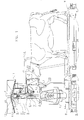
- Figure 1 shows schematically a device for supplying feed to animals, in particular but not exclusively cows.
- the device comprises a framework 1 which, in the embodiment depicted in Figures 1 and 2, is disposed around a central axis 2 and has a substantially circular circumference.
- hoppers 9, 10 At the upper side of the framework 1 there are located hoppers 9, 10.
- the device is adapted to be placed in a position, in other words can be positioned, on a bottom 5, preferably having a bottom portion 8, on which an animal can stand.
- the framework 1 is preferably provided with partitions 4 between adjacent feeding troughs 6.
- the partitions 4 are possibly detachably disposed on the framework 1.
- the partitions prevent an animal from being disturbed by another animal during eating from a feeding trough 6. Because cows eating from a feeding trough 6 come in the immediate vicinity of the partition 4, there is provided a reading device 13 in the partition 4 for reading the data in a step counter fitted to the cows. Such step counters are used inter alia for measuring on the basis of the number of steps whether or not an animal is on heat.
- Partition frames 14 extend from the feeding trough over a distance that equals at least approximately half of the average length of a cow.
- the partition frame is preferably made of stainless steel, although other materials such as synthetic material may be applied as well.
- the partition frames 14 prevent animals standing side by side from leaning too much against each other.
- feeding troughs 6 for the animals are disposed in circular arrangement around the axis 2 in the lower part of the device.
- a first number of the feeding troughs 6 are disposed on the framework in a lower position than a second number of the feeding troughs 6.
- the feeding troughs of the first number overlap the feeding troughs of the second number in a projective view.
- the feeding column is further provided with conveying means comprising a first conveyor 11 and a second conveyor 3, 3' for conveying feed from the hopper 9 respectively 10 to the relevant feeding trough 6.
- a receptacle 12 receives an amount of feed which is conveyed by the first conveyor 11 from the hopper 9, 10 to the receptacle 12.
- a first conveyor 11 an auger, gripper, belt conveyor or any other device known per se for conveying feed may be used.
- the first conveyors 11 convey feed from a hopper 9, 10 upwards for obtaining a highly accurate metering.
- the first conveyors 11 have supply ends corresponding with the discharge ends 21 respectively 22 of the hoppers 9 respectively 10.
- the hoppers 9, 10 are disposed around the central axis 2.
- the discharge ends 21 and 22 of the hoppers 9, 10 alternately stagger in height, the arrangement being such that the discharge ends of juxtaposed hoppers 9, 10 partially overlap each other in a projective view, as is apparent from Figure 1.
- a second conveyor 3, 3' preferably constituted by a tube-shaped chute respectively a channel-shaped chute, is suitable for conveying the amount of feed from the receptacle 12 to the relevant feeding trough 6.
- the third conveyor 18 is preferably disposed so as to be rotatable around the central axis 2. The rotation is effected by a drive member 23, e.g. constituted by an electric motor.
- the second conveyor 3, 3' is disposed so as to be rotatable around the central axis 2; this rotation may be driven by a motor 24. Moreover, the second conveyor 3, 3' is movable from a position in which the feeding troughs of the second number can be filled to a position in which the feeding troughs of the first number can be filled, as is apparent from Figure 2.
- the receptacle 12 For conveying the feed to the tube-shaped chute 3, 3', the receptacle 12 has a bottom which is adapted to be opened. In the embodiment shown in Figure 3 this is realised in that the bottom of the receptacle 12 is constituted by two halves 16 and 17 which are pivotable about an axis 15. When the halves 16, 17 move away from each other, there is created an aperture 18 through which the feed falls into the tube-shaped chute 3, 3'.
- the device comprises a drive member 19 for controlling the opening of the bottom.
- the drive member 19 is controlled by a computer 25 which also controls the order of functioning of the first and second conveyors 11 respectively 3, 3'.
- the receptacle 12 is provided with a weighing device 20 known per se for measuring feed present in the receptacle 12.
- the weighing device 20 may be a load cell on which the receptacle 12 bears via e.g. a leaf spring 27 and a rod assembly 26.
- identification means 7 for identifying an individual animal.
- the identification means 7 are disposed in the partitions 4, but it will be obvious that the identification means may also be disposed at other places, such as e.g. the feeding troughs 6.
- the identity of an animal present at a feeding trough 6 is determined automatically.
- the aid of correspondence tables stored in the memory of e.g. the computer it is possible to supply e.g. the amount of feed intended for that animal. Said amount may be determined with the aid of the weighing device 20.
- the computer With the aid of data from the animal identification means 7 the computer further controls the movement of the tube-shaped chute 3 so that the latter is located over the right feeding trough 6.
- the computer further controls the drive of the conveyors 11.
- a feeding trough 6 For the purpose of giving animals of different heights access to a feeding trough 6 in a simple manner, the height of a feeding trough 6 relative to the bottom 5 is adjustable.
- a feeding trough may be disposed on the framework 1 so as to be movable in height, said movement being realised by e.g. a motor controlled by the computer 25.
- the computer 25 may use data from the animal recognition respectively the animal identification means 7.
- the bottom portion 8 of the bottom 5 may be moved upwards or downwards by means of a lifting device 28.
- the bottom portion 8 slopes downwards in a direction away from the device, as schematically shown in Figure 1.
- an animal height measuring means for measuring the height of an animal.
- Such an animal height measuring means may e.g. be constituted by a camera or a light grid.
- measuring strips 29 or sensors in the form of strips which may be used for height measurement, and possibly for the control of the mutual height adjustment of feeding trough and bottom portion.
- the information from the height measuring means 29 may also be used for controlling a feed metering device supplying feed in metered portions partially with the aid of data from the animal identification device 7 and feeding data stored in the computer 25.
- a feed metering device supplying feed in metered portions partially with the aid of data from the animal identification device 7 and feeding data stored in the computer 25.
- an animal weighing device e.g. a bottom portion designed as a weighing floor.
- the animal height measuring means and the weighing means comprise a data conveying means for conveying measurement data to the computer.
- the computer is provided with a memory containing average growth data for the animal species, preferably in the form of correspondence tables, in relation to weight in dependence of age, and/or in relation to height in dependence of age, and/or in relation to the amount of feed per day per animal in dependence of age, and/or historical growth data of an animal, the feed metering device supplying feed in metered portions with the aid of at least one of said data.
- the device may e.g. be provided with a lighting disposed behind a feeding trough, preferably a central lighting for all feeding troughs.
- the device may be provided with means for combating vermin, and/or means for preventing the formation of condensation in the device, and/or means for cooling an animal.
- the invention also relates to each of the mentioned embodiments per se.
- a partition frame may e.g.
- the invention also relates to a device for accommodating a dairy animal, said device comprising a milking robot, characterized in that the device is provided with signal issuing means for issuing a signal that a dairy animal is expected at the milking robot. Said signal issuing means may be disposed at various strategic places in or outside a shed. Further it will be obvious that a number of the feeding troughs may also be arranged as drinking troughs, in which situation colour and/or design may be used for enabling an animal to distinguish feeding troughs from drinking troughs. The invention is further described with reference to a feeding trough as a feeding parlour, but it will be obvious that the invention is not limited thereto.
Landscapes
- Life Sciences & Earth Sciences (AREA)
- Environmental Sciences (AREA)
- Animal Husbandry (AREA)
- Biodiversity & Conservation Biology (AREA)
- Birds (AREA)
- Zoology (AREA)
- Feeding And Watering For Cattle Raising And Animal Husbandry (AREA)
Applications Claiming Priority (2)
| Application Number | Priority Date | Filing Date | Title |
|---|---|---|---|
| NL1017888A NL1017888C2 (nl) | 2001-04-20 | 2001-04-20 | Inrichting voor het afgeven van voeder aan dieren. |
| NL1017888 | 2001-04-20 |
Publications (2)
| Publication Number | Publication Date |
|---|---|
| EP1250838A2 true EP1250838A2 (fr) | 2002-10-23 |
| EP1250838A3 EP1250838A3 (fr) | 2007-05-30 |
Family
ID=19773272
Family Applications (1)
| Application Number | Title | Priority Date | Filing Date |
|---|---|---|---|
| EP02076475A Withdrawn EP1250838A3 (fr) | 2001-04-20 | 2002-04-16 | Dispositif pour la distribution de nourriture à des animaux |
Country Status (6)
| Country | Link |
|---|---|
| US (1) | US20020152966A1 (fr) |
| EP (1) | EP1250838A3 (fr) |
| JP (1) | JP2002360096A (fr) |
| AU (1) | AU779103B2 (fr) |
| CA (1) | CA2382365A1 (fr) |
| NL (1) | NL1017888C2 (fr) |
Cited By (3)
| Publication number | Priority date | Publication date | Assignee | Title |
|---|---|---|---|---|
| EP2133672A1 (fr) * | 2008-06-13 | 2009-12-16 | Big Dutchman International GmbH | Balance pour volaille |
| WO2010012431A1 (fr) * | 2008-07-28 | 2010-02-04 | Delaval Holding Ab | Procédé et appareil de suivi d'un animal |
| CN112367835A (zh) * | 2018-04-16 | 2021-02-12 | 特种宠物食品公司 | 用于追踪比如哺乳动物例如猫等动物的食物消耗的装置 |
Families Citing this family (4)
| Publication number | Priority date | Publication date | Assignee | Title |
|---|---|---|---|---|
| NL1028674C2 (nl) * | 2005-04-01 | 2006-10-09 | Lely Entpr Ag | Diergerelateerde inrichting voor het begrenzen van de bewegingsvrijheid van een rechtopstaand dier. |
| KR100979526B1 (ko) * | 2008-02-20 | 2010-09-06 | 대한민국 | 가축의 대사생리 측정장치 |
| GB0813778D0 (en) * | 2008-07-28 | 2008-09-03 | Delaval Holding Ab | Monitoring animal condition |
| CA3076866A1 (fr) | 2017-09-26 | 2019-04-04 | Growsafe Systems Ltd. | Systeme de mesure, de surveillance et de gestion de l'absorption d'aliments pour determiner l'efficacite d'alimentation d'animaux individuels d'un cheptel laitier |
Family Cites Families (16)
| Publication number | Priority date | Publication date | Assignee | Title |
|---|---|---|---|---|
| DE927302C (de) * | 1952-11-22 | 1955-05-05 | Karl Apfel | Automatischer Futtertisch |
| US3336907A (en) * | 1966-03-07 | 1967-08-22 | Andy L Thompson | Limited access livestock feeder apparatus |
| DE1607281A1 (de) * | 1967-03-16 | 1970-10-22 | Alois Mayer | Fahrbare automatische Fuetterungsvorrichtung |
| US4029052A (en) * | 1975-11-11 | 1977-06-14 | James Mark Launder | Conveying and weighing system |
| NL8003014A (nl) * | 1979-11-19 | 1981-06-16 | Brinkmann & Niemeijer | Voederautomaat. |
| FR2507776A1 (fr) * | 1981-06-15 | 1982-12-17 | Telemecanique Electrique | Dispositif de pesage automatique d'un animal, application a un dispositif de gestion d'un troupeau et procede de gestion |
| FR2507435A1 (fr) * | 1981-06-15 | 1982-12-17 | Telemecanique Electrique | Dispositif de distribution pour l'alimentation des animaux a dosage gravimetrique |
| FR2513073B1 (fr) * | 1981-09-18 | 1987-10-09 | Inst Tech Porc | Bol d'alimentation pour porc, conforme a la morphologie de la tete de l'animal de facon a eviter le gaspillage et les souillures de l'aliment, et destine a etre monte sur un reservoir d'aliment |
| DE3738156A1 (de) * | 1986-12-05 | 1988-10-27 | Moba Electronic Mobil Automat | Dosiersystem |
| GB9022804D0 (en) * | 1990-10-19 | 1990-12-05 | British Res Agricult Eng | Animal stall |
| GB2264034B (en) * | 1992-01-22 | 1995-04-26 | Aco Polymer Products Ltd | Feeding troughs for animals |
| NL9301260A (nl) * | 1993-07-19 | 1995-02-16 | Texas Industries Inc | Inrichting voor het automatisch melken van dieren. |
| NL1010898C2 (nl) | 1998-12-24 | 2000-06-27 | Lely Research Holding Ag | Voerzuil en/of drinkzuil voor het voederen van dieren. |
| NL1011799C2 (nl) * | 1998-12-24 | 2000-06-27 | Lely Research Holding Ag | Inrichting voor het voeren en/of drenken van dieren. |
| NL1012808C2 (nl) * | 1999-08-11 | 2001-02-13 | Lely Res Holding | Werkwijze voor het lokken van een dier naar een bepaalde plaats. |
| AU773798B2 (en) * | 1999-09-02 | 2004-06-10 | Kristoffer Larsen Innovation A/S | Method for controlling breeding of free-range animals |
-
2001
- 2001-04-20 NL NL1017888A patent/NL1017888C2/nl not_active IP Right Cessation
-
2002
- 2002-04-16 EP EP02076475A patent/EP1250838A3/fr not_active Withdrawn
- 2002-04-18 AU AU34393/02A patent/AU779103B2/en not_active Ceased
- 2002-04-18 CA CA002382365A patent/CA2382365A1/fr not_active Abandoned
- 2002-04-19 US US10/125,502 patent/US20020152966A1/en not_active Abandoned
- 2002-04-19 JP JP2002117855A patent/JP2002360096A/ja not_active Withdrawn
Cited By (5)
| Publication number | Priority date | Publication date | Assignee | Title |
|---|---|---|---|---|
| EP2133672A1 (fr) * | 2008-06-13 | 2009-12-16 | Big Dutchman International GmbH | Balance pour volaille |
| US8707908B2 (en) | 2008-06-13 | 2014-04-29 | Big Dutchman International Gmbh | Poultry weighing apparatus |
| WO2010012431A1 (fr) * | 2008-07-28 | 2010-02-04 | Delaval Holding Ab | Procédé et appareil de suivi d'un animal |
| US8245664B2 (en) | 2008-07-28 | 2012-08-21 | Delaval Holding Ab | Animal monitoring method and apparatus |
| CN112367835A (zh) * | 2018-04-16 | 2021-02-12 | 特种宠物食品公司 | 用于追踪比如哺乳动物例如猫等动物的食物消耗的装置 |
Also Published As
| Publication number | Publication date |
|---|---|
| AU3439302A (en) | 2002-10-24 |
| EP1250838A3 (fr) | 2007-05-30 |
| CA2382365A1 (fr) | 2002-10-20 |
| NL1017888C2 (nl) | 2002-10-29 |
| US20020152966A1 (en) | 2002-10-24 |
| JP2002360096A (ja) | 2002-12-17 |
| AU779103B2 (en) | 2005-01-06 |
Similar Documents
| Publication | Publication Date | Title |
|---|---|---|
| US6619228B2 (en) | Device for automatically supplying a predetermined amount of at least one sort of feed to an animal in a predetermined period | |
| EP1300073B1 (fr) | Dispositif pour distribuer une quantité d'alimentation prédéterminée à un animal dans une période de temps prédéterminée | |
| EP1250839B1 (fr) | Dispositif pour la distribution de nourriture aux animaux | |
| EP1250837B1 (fr) | Dispositif pour la distribution de nourriture à des animaux | |
| EP2151160A2 (fr) | Dispositif pour distribuer des aliments | |
| EP1300075B1 (fr) | Dispositif de distribution automatique d'alimentation pour animaux | |
| EP1250838A2 (fr) | Dispositif pour la distribution de nourriture à des animaux | |
| EP1300070B1 (fr) | Installation pour distribuer une quantité d'alimentation à un animal laitier dans une période de temps prédéterminée | |
| EP1300072B1 (fr) | Dispositif et procédé de distribution automatique d'au moins deux sortes de fourrage à des animaux | |
| US4554888A (en) | Compact animal feeder trough | |
| EP1527680B1 (fr) | Dispositif et procédé de distribution automatique d'alimentation pour animaux | |
| EP1315415A1 (fr) | Systeme et procede d'alimentation individuelle animale | |
| Dawson | Equipment for feeding concentrates in and out of the parlour | |
| EP3338543A1 (fr) | Procédé d'alimentation de vaches laitières avec un dosage spécial d'aliments pour animaux et dispositif mettant en uvre ce procédé |
Legal Events
| Date | Code | Title | Description |
|---|---|---|---|
| PUAI | Public reference made under article 153(3) epc to a published international application that has entered the european phase |
Free format text: ORIGINAL CODE: 0009012 |
|
| AK | Designated contracting states |
Kind code of ref document: A2 Designated state(s): AT BE CH CY DE DK ES FI FR GB GR IE IT LI LU MC NL PT SE TR |
|
| AX | Request for extension of the european patent |
Free format text: AL;LT;LV;MK;RO;SI |
|
| RIC1 | Information provided on ipc code assigned before grant |
Ipc: A01K 1/02 20060101ALI20061229BHEP Ipc: A01K 5/02 20060101AFI20020725BHEP |
|
| PUAL | Search report despatched |
Free format text: ORIGINAL CODE: 0009013 |
|
| AK | Designated contracting states |
Kind code of ref document: A3 Designated state(s): AT BE CH CY DE DK ES FI FR GB GR IE IT LI LU MC NL PT SE TR |
|
| AX | Request for extension of the european patent |
Extension state: AL LT LV MK RO SI |
|
| 17P | Request for examination filed |
Effective date: 20070702 |
|
| AKX | Designation fees paid |
Designated state(s): AT BE CH CY DE DK ES FI FR GB GR IE IT LI LU MC NL PT SE TR |
|
| 17Q | First examination report despatched |
Effective date: 20080121 |
|
| STAA | Information on the status of an ep patent application or granted ep patent |
Free format text: STATUS: THE APPLICATION IS DEEMED TO BE WITHDRAWN |
|
| 18D | Application deemed to be withdrawn |
Effective date: 20090307 |