EP1250560B1 - Multilayer glass pane for safe motor vehicles - Google Patents
Multilayer glass pane for safe motor vehicles Download PDFInfo
- Publication number
- EP1250560B1 EP1250560B1 EP00990590A EP00990590A EP1250560B1 EP 1250560 B1 EP1250560 B1 EP 1250560B1 EP 00990590 A EP00990590 A EP 00990590A EP 00990590 A EP00990590 A EP 00990590A EP 1250560 B1 EP1250560 B1 EP 1250560B1
- Authority
- EP
- European Patent Office
- Prior art keywords
- leg
- glass pane
- layer glass
- pane
- several
- Prior art date
- Legal status (The legal status is an assumption and is not a legal conclusion. Google has not performed a legal analysis and makes no representation as to the accuracy of the status listed.)
- Expired - Lifetime
Links
Images

Classifications
-
- B—PERFORMING OPERATIONS; TRANSPORTING
- B32—LAYERED PRODUCTS
- B32B—LAYERED PRODUCTS, i.e. PRODUCTS BUILT-UP OF STRATA OF FLAT OR NON-FLAT, e.g. CELLULAR OR HONEYCOMB, FORM
- B32B17/00—Layered products essentially comprising sheet glass, or glass, slag, or like fibres
- B32B17/06—Layered products essentially comprising sheet glass, or glass, slag, or like fibres comprising glass as the main or only constituent of a layer, next to another layer of a specific material
- B32B17/10—Layered products essentially comprising sheet glass, or glass, slag, or like fibres comprising glass as the main or only constituent of a layer, next to another layer of a specific material of synthetic resin
- B32B17/10005—Layered products essentially comprising sheet glass, or glass, slag, or like fibres comprising glass as the main or only constituent of a layer, next to another layer of a specific material of synthetic resin laminated safety glass or glazing
- B32B17/10165—Functional features of the laminated safety glass or glazing
- B32B17/10293—Edge features, e.g. inserts or holes
-
- B—PERFORMING OPERATIONS; TRANSPORTING
- B32—LAYERED PRODUCTS
- B32B—LAYERED PRODUCTS, i.e. PRODUCTS BUILT-UP OF STRATA OF FLAT OR NON-FLAT, e.g. CELLULAR OR HONEYCOMB, FORM
- B32B17/00—Layered products essentially comprising sheet glass, or glass, slag, or like fibres
- B32B17/06—Layered products essentially comprising sheet glass, or glass, slag, or like fibres comprising glass as the main or only constituent of a layer, next to another layer of a specific material
- B32B17/10—Layered products essentially comprising sheet glass, or glass, slag, or like fibres comprising glass as the main or only constituent of a layer, next to another layer of a specific material of synthetic resin
- B32B17/10005—Layered products essentially comprising sheet glass, or glass, slag, or like fibres comprising glass as the main or only constituent of a layer, next to another layer of a specific material of synthetic resin laminated safety glass or glazing
- B32B17/10009—Layered products essentially comprising sheet glass, or glass, slag, or like fibres comprising glass as the main or only constituent of a layer, next to another layer of a specific material of synthetic resin laminated safety glass or glazing characterized by the number, the constitution or treatment of glass sheets
- B32B17/10036—Layered products essentially comprising sheet glass, or glass, slag, or like fibres comprising glass as the main or only constituent of a layer, next to another layer of a specific material of synthetic resin laminated safety glass or glazing characterized by the number, the constitution or treatment of glass sheets comprising two outer glass sheets
- B32B17/10045—Layered products essentially comprising sheet glass, or glass, slag, or like fibres comprising glass as the main or only constituent of a layer, next to another layer of a specific material of synthetic resin laminated safety glass or glazing characterized by the number, the constitution or treatment of glass sheets comprising two outer glass sheets with at least one intermediate layer consisting of a glass sheet
-
- F—MECHANICAL ENGINEERING; LIGHTING; HEATING; WEAPONS; BLASTING
- F41—WEAPONS
- F41H—ARMOUR; ARMOURED TURRETS; ARMOURED OR ARMED VEHICLES; MEANS OF ATTACK OR DEFENCE, e.g. CAMOUFLAGE, IN GENERAL
- F41H5/00—Armour; Armour plates
- F41H5/02—Plate construction
- F41H5/04—Plate construction composed of more than one layer
- F41H5/0407—Transparent bullet-proof laminatesinformative reference: layered products essentially comprising glass in general B32B17/06, e.g. B32B17/10009; manufacture or composition of glass, e.g. joining glass to glass C03; permanent multiple-glazing windows, e.g. with spacing therebetween, E06B3/66
-
- F—MECHANICAL ENGINEERING; LIGHTING; HEATING; WEAPONS; BLASTING
- F41—WEAPONS
- F41H—ARMOUR; ARMOURED TURRETS; ARMOURED OR ARMED VEHICLES; MEANS OF ATTACK OR DEFENCE, e.g. CAMOUFLAGE, IN GENERAL
- F41H5/00—Armour; Armour plates
- F41H5/26—Peepholes; Windows; Loopholes
- F41H5/263—Mounting of transparent armoured panels, e.g. bulletproof windows on vehicles
Definitions
- the invention relates to a laminated glass pane for Security vehicles, according to the generic term of the first Claim consisting of several individual disks is composed, with at least the outer pane other panes at least their outer edge towered over in areas and on at least one edge of the Disk a first securing element is attached.
- an armored glass pane is in Stepped glass design described on its upper edge is tapered towards the vehicle interior, wherein the resulting wedge joint by means of an Interior arranged armor plate is covered.
- the Armor plate is not on the armor plate attached.
- the support and guidance of the bulletproof glass forms a frame profile, which the bulletproof glass from limited at the top, front and rear and as a complex component is trained.
- the frame profile shows Supplementary profile, which is essentially U-shaped Has cross section and includes the edge of the bulletproof glass pane.
- a step glass version is also described in DE 196 39 607 A1 described, being between two discs Spacers and a seal can be arranged.
- DE 41 42 416 A1 and DE 44 15 879 C2 each have one Tempered glass window for motor vehicles described in the marginal area along the edge running armor element in the form of an angle.
- the Angle borders according to DE 41 42 416 A1 with one leg to one pointing towards the outside of the vehicle The disc protrudes and the other angle lies on the Vehicle inside.
- DE 44 15 879 the angle runs with his thighs in the edge of the window.
- Both Solutions have a high design effort because these angular profiles exactly the curved course must follow the face of the armored disk. Farther it is necessary in both cases that the interior of the The bulletproof material provided for the vehicle Edge area of the safety glass to lead in projectiles hitting a steep angle not in the To let vehicle interior penetrate.
- a safety vehicle continues to exist fundamental problem in that in particular Edge area of the outer pane to the edge area of the subsequent safety window package and up to bulletproof linings in the interior of the vehicle is unprotected.
- the invention has for its object a To develop laminated glass for safety motor vehicles, which is inexpensive and easy to manufacture and requires little joining and assembly effort.
- the Laminated glass is known from several Individual panes assembled, at least the Outer pane the other panes in a stepped manner on their Outer edge at least partially overhangs and on at least one edge of the disk a first leg of a Securing element is attached.
- the securing element has at least two further legs, which are essentially perpendicular to the first leg are arranged.
- the second leg overlaps the Area up to that adjacent to the composite pane Body part or the bulletproof inner lining of the vehicle and the third leg overlaps the Laminated pane.
- the third leg can either between two panes or on the inside of the Inner pane be attached. At least the first and the second legs are designed as separate components.
- connection between the first and the second leg is preferably carried out in a form-fitting manner by an optionally detachable one Plug connection.
- the second and / or the third leg have recesses in the protrusions of the first Intervene leg or vice versa.
- the legs are made by suitable Securing elements fixed to one another.
- the securing element can also preferably be a fourth Have legs of the second and third Towering in the direction of the vehicle interior.
- the second and third legs are first strip-shaped element as well as the first and fourth Leg as a second strip-shaped element educated.
- the position of the second and third leg e.g. with locking pins in the fourth leg of the second strip-shaped component, which engage in corresponding recesses in this and the second in front towards the inner pane Hold the strip-shaped element in position.
- the Pins can be cylindrical or wedge pins be and are also preferred by Securing elements e.g. Positioned by pins.
- the legs can be the same or different Materials exist. At least the second is preferred Thigh that extends the area up to the bulletproof Body parts or linings overlap high-strength bulletproof steel sheet, bulletproof Ceramic or other bullet-proof material educated.
- the third leg is also preferably made a corresponding bulletproof material. On the first leg and, if present, on the fourth Thighs, will have lower demands on the Bombardment security provided, this can therefore from a Sheet steel with a comparatively lower strength or also made of plastic or fiber composite material consist.
- the attachment of the first leg to the edge of the pane is preferably produced by an adhesive connection. Then the second leg can be easily Insert positively connected to the first element and then fixed in position by securing elements become.
- the joining and Assembly process is compared to conventional solutions also significantly simplified.
- the third leg secures the edge area of the adjoining one Glass panes and the second leg the area up to Body with the bulletproof there Linings. This will make the bulletproof, especially with edge bombardment, significantly increased since the endangered edge areas of the bulletproof linings the body of the safety motor vehicle additionally be secured. It doesn't just fire perpendicular to the disc, but also in Longitudinal disc direction, withstood.
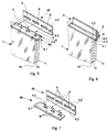
- the laminated glass panes 1 is gem. 1 to 6 composed of several individual panes. Between the Outer pane 1a and inner pane 1i are one or several washers 1z arranged. The outer pane 1a towers over the other panes and overlaps them adjoining body parts 2 and thus in the direction arranged to the vehicle interior on the body 2 Interior lining 3 made of bulletproof material. On the in Comparison to the outer pane 1a reset others Disks 1z and 1i is a securing element 4 with its first leg 4.1 attached, preferably glued. The Fuse 4 is shown in the illustration. Fig. 1 and 2 cross-shaped in cross section.
- first legs 4.1 are a second leg 4.2 and one third leg 4.3 arranged, the second leg 4.2 the area up to which the composite pane 1 adjacent body part 2 and the bulletproof Inner lining 3 and the third leg 4.3 the Laminated glass pane 1 overlaps.
- the third leg 4.3 is gem.
- Fig. 1 on the in the direction to the passenger compartment facing side of the inner pane 1i Laminated glass pane 1 arranged and gem.
- Under the third leg 4.3 can be as shown in Fig. 2 be a correspondingly reset washer 1z or there is an air cushion.
- the two legs 4.1 and 4.4 are as a common stripe-shaped first Component 4a and the legs 4.2 and 4.3 as a common strip-shaped second component 4b formed.
- Securing the second strip-shaped component 4b takes place according to Fig. 1 with a positive Plug connection by locking pins 5, which in corresponding recesses 6 in the leg 4.4 of the Intervene securing element 4 (see also Fig. 5 and 6).
- the locking pins 5 are advantageously also fixed in position, e.g. also by locking pins or with locking lacquer (not shown).
- 2 can the second strip-shaped component 4b on the first strip-shaped component 4a also by an adhesive connection be attached, e.g. in the execution acc. FIG. 2 possible.
- the third leg 4.3 of the securing element 4 is not fixed to the adjacent disks 1i, 1z connected to avoid tension.
- FIG. 3 A variant of a T-shaped in cross section
- the securing element 4 is shown in FIG. 3.
- the Inner pane 1i is compared to the adjoining one Intermediate disc 1z reset to its face the third leg 4.3 of the Securing element 4, which is also on the delimiting intermediate washer 1z.
- FIG. 4 A variant with one piece from the first and fourth leg 4.1, 4.4 formed first strip-shaped element is shown in Fig. 4.
- the Legs 4.2 and 4.3 are not in one piece, but separate formed with the first strip-shaped element 4a connected by a plug connection and fixed in position by locking pins 5.
- Fig. 5 is shown three-dimensionally schematically how the first strip-shaped element 4a on the Laminated glass pane 1 is glued to its leg 4.1.
- the design corresponds to that shown in FIG. 1 Variant.
- the leg 4.4 has projections V.
- To the second strip-shaped component 4b becomes rectangular positioned.
- the component 4b has cutouts A in the engage projections V during assembly.
- In the thigh 4.4 are also recesses 6 for locking pins 5 intended.
- This version after completion of the assembly shows Fig. 6.
- the first strip-shaped component 4a and second strip-shaped component now form that Securing element 4, the second strip-shaped Component by locking pins 5, which in the Engage recesses 6, is fixed in position.
- the securing element 4 was thus a simple Plug connection of two components 4a and 4b, in particular Steel sheet strips are formed, which are simply the Have the contour of the disc adjusted.
- the legs by suitable Securing elements are fixed to one another in such a way that that in the longitudinal direction of the first strip-shaped component 4a groove-shaped recesses N are present in the projections are in which by a movement of the second strip-shaped component in the longitudinal direction of between engage the remaining webs S in the recesses A (see Fig. 7).
- the illustrated embodiments for Establishing a positive connection between the Components 4a, 4b are also numerous other variants Formation of a plug connection possible. So can for example when executing the second strip-shaped element 4a or the first leg 4.1 made of plastic or fiber composite material projections on these components in corresponding recesses in the corresponding component respectively.
Landscapes
- Engineering & Computer Science (AREA)
- General Engineering & Computer Science (AREA)
- Joining Of Glass To Other Materials (AREA)
- Laminated Bodies (AREA)
Abstract
Description
Die Erfindung betrifft eine Verbundglasscheibe für Sicherheitskraftfahrzeuge, nach dem Oberbegriff des ersten Patentanspruchs, die aus mehreren Einzelscheiben zusammengesetzt ist, wobei zumindest die Außenscheibe die anderen Scheiben stufenförmig ihrer Außenkante zumindest bereichsweise überragt und an wenigstens einem Rand der Scheibe ein erstes Sicherungselement befestigt ist.The invention relates to a laminated glass pane for Security vehicles, according to the generic term of the first Claim consisting of several individual disks is composed, with at least the outer pane other panes at least their outer edge towered over in areas and on at least one edge of the Disk a first securing element is attached.
Es sind zahlreiche Lösungen zum Aufbau von Sicherheitsscheiben für Kraftfahrzeuge bekannt, wobei meist mehrere Verbundscheiben aus Sicherheitsglas zusammengesetzt werden, zwischen denen Folien oder fluidgefüllte Zwischenräume vorgesehen sind und eine oder mehrere Schichten aus Polycarbonatglas bestehen können (DE 43 36 321 A1, DE 195 48 338 A1, EP 302 959 A1).There are numerous solutions for building Safety panes for motor vehicles are known, mostly several composite panes composed of safety glass between which foils or fluid-filled Gaps are provided and one or more Layers of polycarbonate glass can exist (DE 43 36 321 A1, DE 195 48 338 A1, EP 302 959 A1).
In DE 36 39 781 C1 wird eine Panzerglasscheibe in Stufenglasausführung beschrieben, die an ihrer oberen Kante in Richtung zum Fahrzeuginnenraum abgeschrägt ist, wobei die sich dadurch bildende Keilfuge mittels einer im Innenraum angeordneten Panzerplatte überdeckt ist. Die Panzerplatte ist dabei nicht an der Panzerscheibe befestigt. Die Halterung und Führung der Panzerglasscheibe bildet ein Rahmenprofil, welches die Panzerglasscheibe von oben, vorn und hinten begrenzt und als komplexes Bauteil ausgebildet ist. Das Rahmenprofil weist ein Ergänzungsprofil auf, das einen im wesentlichen U-förmigen Querschnitt hat und den Rand der Panzerglasscheibe umfaßt.In DE 36 39 781 C1 an armored glass pane is in Stepped glass design described on its upper edge is tapered towards the vehicle interior, wherein the resulting wedge joint by means of an Interior arranged armor plate is covered. The Armor plate is not on the armor plate attached. The support and guidance of the bulletproof glass forms a frame profile, which the bulletproof glass from limited at the top, front and rear and as a complex component is trained. The frame profile shows Supplementary profile, which is essentially U-shaped Has cross section and includes the edge of the bulletproof glass pane.
Ebenfalls eine Stufenglasausführung wird in DE 196 39 607 A1 beschrieben, wobei zwischen zwei Scheiben ein Abstandhalter und eine Dichtung angeordnet sein können.A step glass version is also described in DE 196 39 607 A1 described, being between two discs Spacers and a seal can be arranged.
In DE 41 42 416 A1 und in DE 44 15 879 C2 wird jeweils eine aus Panzerglas bestehende Fensterscheibe für Kraftfahrzeuge beschrieben, die im Randbereich ein längs des Randes verlaufendes Panzerelement in Form eines Winkels trägt. Der Winkel grenzt dabei gem. DE 41 42 416 A1 mit einem Schenkel an einen in Richtung zur Außenseite des Fahrzeugs weisenden Vorsprung der Scheibe an und der andere Winkel liegt an der Fahrzeuginnenseite. Nach DE 44 15 879 verläuft der Winkel mit seinen Schenkeln in der Randstufe des Fensters. Beide Lösungen weisen einen hohen konstruktiven Aufwand auf, da diese winkelförmigen Profile genau dem gekrümmten Verlauf der Stirnfläche der Panzerscheibe folgen müssen. Weiterhin ist es in beiden Fällen notwendig, das im Innenraum des Fahrzeuges vorgesehene beschußsichere Material über den Randbereich des Sicherheitsglases zu führen, um auch in einem steilen Winkel auftreffende Projektile nicht in den Fahrzeuginnenraum eindringen zu lassen.DE 41 42 416 A1 and DE 44 15 879 C2 each have one Tempered glass window for motor vehicles described in the marginal area along the edge running armor element in the form of an angle. The Angle borders according to DE 41 42 416 A1 with one leg to one pointing towards the outside of the vehicle The disc protrudes and the other angle lies on the Vehicle inside. According to DE 44 15 879 the angle runs with his thighs in the edge of the window. Both Solutions have a high design effort because these angular profiles exactly the curved course must follow the face of the armored disk. Farther it is necessary in both cases that the interior of the The bulletproof material provided for the vehicle Edge area of the safety glass to lead in projectiles hitting a steep angle not in the To let vehicle interior penetrate.
Bei Sicherheitskraftfahrzeugen besteht weiterhin ein grundlegendes Problem darin, daß insbesondere der Randbereich der Außenscheibe bis zum Randbereich des sich anschließenden Sicherheitsscheibenpaketes und bis zu den beschußsicheren Auskleidungen im Innenraum des Fahrzeuges ungeschützt ist.A safety vehicle continues to exist fundamental problem in that in particular Edge area of the outer pane to the edge area of the subsequent safety window package and up to bulletproof linings in the interior of the vehicle is unprotected.
Dazu wird in DE 198 03 435 C1 eine Lösung beschrieben, bei welcher die Verbundscheibe einen Streifen aus beschußsicherem Material aufweist, der den Bereich bis zu den beschußsicheren Auskleidungen überlappt. Problematisch ist dabei die Herstellung einer festen Verbindung zwischen dem Strukturglas und dem Streifen aus beschußsicherem Material.A solution to this is described in DE 198 03 435 C1, at which made the composite disc a strip bulletproof material that covers the area up to the bulletproof linings overlap. Problematic is the establishment of a firm connection between the structural glass and the strip of bulletproof Material.
Der Erfindung liegt die Aufgabe zugrunde, eine Verbundglasscheibe für Sicherheitskraftfahrzeuge zu entwickeln, die kostengünstig und einfach herstellbar ist und geringen Füge- und Montageaufwand erfordert.The invention has for its object a To develop laminated glass for safety motor vehicles, which is inexpensive and easy to manufacture and requires little joining and assembly effort.
Diese Aufgabe wird mit den Merkmalen des ersten Patentanspruchs gelöst. Vorteilhafte Weiterbildungen ergeben sich aus den Unteransprüchen. Die Verbundglasscheibe ist bekannter Weise aus mehreren Einzelscheiben zusammengesetzt, wobei zumindest die Außenscheibe die anderen Scheiben stufenförmig an ihrer Außenkante zumindest bereichsweise überragt und an wenigstens einem Rand der Scheibe ein erster Schenkel eines Sicherungselementes befestigt ist. Erfindungsgemäß weist das Sicherungselement wenigstens zwei weitere Schenkel auf, die im wesentlichen rechtwinklig zum ersten Schenkel angeordnet sind. Der zweite Schenkel überlappt dabei den Bereich bis zu dem an die Verbundscheibe angrenzenden Karosserieteil oder der beschußsicheren Innenverkleidung des Fahrzeuges und der dritte Schenkel überlappt die Verbundscheibe. Der dritte Schenkel kann dabei entweder zwischen zwei Scheiben oder an der Innenseite der Innenscheibe angebracht sein. Zumindest der erste und der zweite Schenkel sind als separate Bauteile ausgebildet.This task is done with the characteristics of the first Claim resolved. Advantageous further training result from the subclaims. The Laminated glass is known from several Individual panes assembled, at least the Outer pane the other panes in a stepped manner on their Outer edge at least partially overhangs and on at least one edge of the disk a first leg of a Securing element is attached. According to the invention the securing element has at least two further legs, which are essentially perpendicular to the first leg are arranged. The second leg overlaps the Area up to that adjacent to the composite pane Body part or the bulletproof inner lining of the vehicle and the third leg overlaps the Laminated pane. The third leg can either between two panes or on the inside of the Inner pane be attached. At least the first and the second legs are designed as separate components.
Die Verbindung zwischen dem ersten und dem zweiten Schenkel erfolgt vorzugsweise formschlüssig durch eine ggf. lösbare Steckverbindung. Der zweite und/oder der dritte Schenkel weisen Aussparungen auf, in die Vorsprünge des ersten Schenkels eingreifen oder umgekehrt.The connection between the first and the second leg is preferably carried out in a form-fitting manner by an optionally detachable one Plug connection. The second and / or the third leg have recesses in the protrusions of the first Intervene leg or vice versa.
Die Schenkel werden dabei durch geeignete Sicherungselemente zueinander lagefixiert.The legs are made by suitable Securing elements fixed to one another.
Das Sicherungselement kann auch bevorzugt einen vierten Schenkel aufweisen, der den zweiten und den dritten Schenkel in Richtung zum Fahrzeuginnenraum überragt. Der zweite und der dritte Schenkel sind als ein erstes streifenförmiges Element sowie der erste und der vierte Schenkel als ein zweites streifenförmiges Element ausgebildet. In diesem Fall erfolgt die Lagefixierung des zweiten und dritten Schenkels z.B. durch Sicherungsstifte im vierten Schenkel des zweiten streifenförmigen Bauteiles, die in entsprechende Ausnehmungen in diesem eingreifen und das in Richtung zur Innenscheibe davor angeordnete zweite streifenförmige Element in seiner Position halten. Die Stifte können als Zylinder- oder Keilstifte ausgebildet sein und werden bevorzugt ebenfalls durch Sicherungselemente z.B. durch Stifte lagepositioniert.The securing element can also preferably be a fourth Have legs of the second and third Towering in the direction of the vehicle interior. The second and third legs are first strip-shaped element as well as the first and fourth Leg as a second strip-shaped element educated. In this case the position of the second and third leg e.g. with locking pins in the fourth leg of the second strip-shaped component, which engage in corresponding recesses in this and the second in front towards the inner pane Hold the strip-shaped element in position. The Pins can be cylindrical or wedge pins be and are also preferred by Securing elements e.g. Positioned by pins.
Die Schenkel können aus gleichen oder unterschiedlichen Materialien bestehen. Bevorzugt ist mindestens der zweite Schenkel, der den Bereich bis zu den beschußsicheren Karosserieteilen oder -auskleidungen überlappt, aus hochfestem beschußsicheren Stahlblech, beschußsicherer Keramik oder einem anderen beschußhemmenden Material ausgebildet. Auch der dritte Schenkel wird vorzugsweise aus einem entsprechenden beschußsicheren Werkstoff gefertigt. An dem ersten Schenkel und, wenn vorhanden, an dem vierten Schenkel, werden geringere Anforderungen an die Beschußsicherheit gestellt, diese können daher aus einem Stahlblech mit einer vergleichsweise geringeren Festigkeit oder auch aus Kunststoff oder Faserverbundmaterial bestehen.The legs can be the same or different Materials exist. At least the second is preferred Thigh that extends the area up to the bulletproof Body parts or linings overlap high-strength bulletproof steel sheet, bulletproof Ceramic or other bullet-proof material educated. The third leg is also preferably made a corresponding bulletproof material. On the first leg and, if present, on the fourth Thighs, will have lower demands on the Bombardment security provided, this can therefore from a Sheet steel with a comparatively lower strength or also made of plastic or fiber composite material consist.
Die Befestigung des ersten Schenkels am Rand der Scheibe wird bevorzugt durch eine Klebeverbindung hergestellt. Anschließend kann der zweite Schenkel durch einfaches Einstecken formschlüssig mit dem ersten Element verbunden und anschließend durch Sicherungselemente lagefixiert werden.The attachment of the first leg to the edge of the pane is preferably produced by an adhesive connection. Then the second leg can be easily Insert positively connected to the first element and then fixed in position by securing elements become.
Alternativ besteht die Möglichkeit, auch den dritten Schenkel an die Innenscheibe oder zwischen zwei Scheiben zu kleben. Die Lagepositionierung mittels Stiften kann dann entfallen. Alternatively there is the option of the third Thighs to the inner pane or between two panes glue. The position positioning using pins can then omitted.
Durch die Verwendung von separat ausgebildeten Schenkeln des Sicherungselementes ist es möglich, diese dem Verlauf der Scheibenkontur besser anzupassen. Der Füge- und Montageprozeß wird im Vergleich zu herkömmlichen Lösungen ebenfalls wesentlich vereinfacht. Der dritte Schenkel sichert dabei den Randbereich der sich anschließenden Glasscheiben und der zweite Schenkel den Bereich bis zur Karosserie mit den dort befindlichen beschußsicheren Auskleidungen. Damit wird die Beschußsicherheit, insbesondere bei Randbeschuß, wesentlich erhöht, da die gefährdeten Randbereiche der beschußsicheren Auskleidungen der Karosserie des Sicherheitskraftfahrzeuges zusätzlich gesichert werden. Damit wird nicht nur einem Beschuß senkrecht zur Scheibe, sondern auch in Scheibenlängsrichtung, standgehalten.Through the use of separately designed legs of the securing element, it is possible to follow the course to better adapt the lens contour. The joining and Assembly process is compared to conventional solutions also significantly simplified. The third leg secures the edge area of the adjoining one Glass panes and the second leg the area up to Body with the bulletproof there Linings. This will make the bulletproof, especially with edge bombardment, significantly increased since the endangered edge areas of the bulletproof linings the body of the safety motor vehicle additionally be secured. It doesn't just fire perpendicular to the disc, but also in Longitudinal disc direction, withstood.
Die Erfindung wird nachfolgend anhand von Ausführungsbeispielen und zugehörigen Zeichnungen näher erläutert.The invention is described below using exemplary embodiments and associated drawings explained in more detail.
Es zeigen:
- Fig. 1:
- Verbundglasscheibe mit einem Sicherungselement,
mit vier Schenkeln, wobei die Schenkel 4.1 und
4.4 sowie die Schenkel 4.2 und 4.3 als jeweils
ein
streifenförmiges Bauteil - Fig. 2:
- Verbundglasscheibe gem. Fig. 1 mit einem Schenkel 4.3 zwischen zwei Scheiben;
- Fig. 3:
- Verbundglasscheibe gem. Fig. 1 mit einem Schenkel
4.3 der an der Stirnseite der
Innenscheibe 1i und an der sich anschließenden Scheibe anliegt, - Fig. 4:
- Verbundglasscheibe gem. Fig. 1 mit separaten Schenkeln 4.2, 4.3;
- Fig. 5:
- dreidimensionale schematische Darstellung des an
der Glasscheibe befestigten ersten
streifenförmiges Bauteil 4a (gebildet aus Schenkel 4.1 und 4.4) vor Montage des zweitenstreifenförmigen Bauteils 4b (gebildet aus Schenkel 4.2 und 4.3); - Fig. 6:
- Darstellung gem. Fig. 4 nach erfolgter Montage
- Fig. 7:
- beide
streifenförmige Bauteile streifenförmige Bauteil 4a in Längsausdehnung zusätzliche Aussparungen N aufweist.
- Fig. 1:
- Laminated glass pane with a securing element, with four legs, wherein the legs 4.1 and 4.4 and the legs 4.2 and 4.3 are each formed as a strip-
shaped component - Fig. 2:
- Laminated glass pane acc. 1 with a leg 4.3 between two disks;
- Fig. 3:
- Laminated glass pane acc. 1 with a leg 4.3 which rests on the end face of the
inner pane 1i and on the adjoining pane, - Fig. 4:
- Laminated glass pane acc. 1 with separate legs 4.2, 4.3;
- Fig. 5:
- three-dimensional schematic representation of the first strip-shaped
component 4a (formed from legs 4.1 and 4.4) fastened to the glass pane before assembly of the second strip-shapedcomponent 4b (formed from legs 4.2 and 4.3); - Fig. 6:
- Representation acc. Fig. 4 after assembly
- Fig. 7:
- both strip-shaped
components component 4a having additional recesses N in the longitudinal extent.
Die Verbundglasscheiben 1 ist gem. Fig. 1 bis 6 aus
mehreren Einzelscheiben zusammengesetzt. Zwischen der
Außenscheibe 1a und der Innenscheibe 1i sind eine oder
mehrere Zwischenscheiben 1z angeordnet. Die Außenscheibe 1a
überragt die anderen Scheiben und überlappt die sich
anschließenden Karosserieteile 2 und somit die in Richtung
zum Fahrzeuginnenraum an der Karosserie 2 angeordnete
Innenverkleidung 3 aus beschußsicherem Material. An dem im
Vergleich zur Außenscheibe 1a zurückgesetzten anderer
Scheiben 1z und 1i ist ein Sicherungselement 4 mit seinem
ersten Schenkel 4.1 befestigt, vorzugsweise verklebt. Das
Sicherungselement 4 ist in der Darstellung gem. Fig. 1 und
2 im Querschnitt kreuzförmig ausgebildet. Rechtwinklig zum
ersten Schenkel 4.1 sind ein zweiter Schenkel 4.2 und ein
dritter Schenkel 4.3 angeordnet, wobei der zweite Schenkel
4.2 den Bereich bis zu dem sich an die Verbundscheibe 1
angrenzende Karosserieteil 2 und die beschußsicheren
Innenverkleidung 3 und der dritte Schenkel 4.3 die
Verbundglasscheibe 1 überlappt.The
Der dritte Schenkel 4.3 ist gem. Fig. 1 an der in Richtung
zum Fahrgastraum weisenden Seite der Innenscheibe 1i der
Verbundglasscheibe 1 angeordnet und gem. Fig. 2 zwischen
der Innenscheibe 1i und einer Zwischenscheibe 1z. Unter dem
dritten Schenkel 4.3 kann dabei wie in Fig. 2 dargestellt
eine entsprechend zurückgesetzte Zwischenscheibe 1z sein
oder sich ein Luftpolster befinden. Die beiden Schenkel 4.1
und 4.4 sind als ein gemeinsames streifenförmiges erstes
Bauteil 4a und die Schenkel 4.2 und 4.3 als ein gemeinsames
streifenförmiges zweites Bauteil 4b ausgebildet.The third leg 4.3 is gem. Fig. 1 on the in the direction
to the passenger compartment facing side of the
Die Sicherung des zweiten streifenförmigen Bauteils 4b
erfolgt gem. Fig. 1 bei einer formschlüssigen
Steckverbindung durch Sicherungsstifte 5, die in
entsprechende Ausnehmungen 6 im Schenkel 4.4 des
Sicherungselementes 4 eingreifen (s. auch Fig. 5 und 6).
Die Sicherungsstifte 5 werden vorteilhafterweise ebenfalls
lagefixiert, z.B. ebenfalls durch Sicherungsstifte oder
durch Sicherungslack (nicht dargestellt). Gemäß Fig. 2 kann
das zweite streifenförmige Bauteil 4b am ersten
streifenförmigen Bauteil 4a auch durch eine Klebeverbindung
befestigt sein, dies ist z.B. bei der Ausführung gem. Fig.
2 möglich. Der dritte Schenkel 4.3 des Sicherungselementes
4 ist dabei nicht fest mit den angrenzenden Scheiben 1i, 1z
verbunden, um Spannungen zu vermeiden.Securing the second strip-shaped
Eine Variante eines im Querschnitt T-förmigen
Sicherungselements 4 zeigt Fig. 3. Am Sicherungselement 4
sind drei Schenkel 4.1, 4.2, 4.3 vorhanden. Die
Innenscheibe 1i ist im Vergleich zu der sich anschließenden
Zwischenscheibe 1z zurückgesetzt, an ihre Stirnseite
schließt sich der dritte Schenkel 4.3 des
Sicherungselements 4 an, der ebenfalls an der
nächstliegenden Zwischenscheibe 1z abgrenzt. Dem dritten
Schenkel 4.3 gegenüberliegend und mit diesem zu einem
zweiten Bauteil 4b einteilig verbunden, liegt der zweite
Schenkel 4.2 gegenüber und überlappt den Bereich bis zur
Karosserie 2 und zur Innenverkleidung 3.A variant of a T-shaped in cross section
The securing
Eine Ausführungsvariante mit einteilig aus erstem und
viertem Schenkel 4.1, 4.4 gebildetem ersten
streifenförmigen Element ist in Fig. 4 dargestellt. Die
Schenkel 4.2 und 4.3 sind nicht einteilig, sondern separat
ausgebildet, mit dem ersten streifenförmigen Element 4a
durch eine Steckverbindung formschlüssig verbunden und
durch Sicherungsstifte 5 lagefixiert. A variant with one piece from the first and
fourth leg 4.1, 4.4 formed first
strip-shaped element is shown in Fig. 4. The
Legs 4.2 and 4.3 are not in one piece, but separate
formed with the first strip-shaped
In Fig. 5 ist dreidimensional schematisch dargestellt, wie
das erste streifenförmige Element 4a an der
Verbundglasscheibe 1 mit seinem Schenkel 4.1 verklebt ist.
Die Ausführung entspricht der in Fig. 1 dargestellten
Variante. Der Schenkel 4.4 weist Vorsprünge V auf. Dazu
rechtwinklig wird das zweite streifenförmige Bauteil 4b
positioniert. Das Bauteil 4b besitzt Aussparungen A in die
bei Montage die Vorsprüngen V eingreifen. Im Schenkel 4.4
sind weiterhin Ausnehmungen 6 für Sicherungsstifte 5
vorgesehen. Diese Ausführung nach Beendigung der Montage
zeigt Fig. 6. Das erste streifenförmige Bauteil 4a und das
zweite streifenförmige Bauteil bilden nun das
Sicherungselement 4, wobei das zweite streifenförmige
Bauteil durch Sicherungsstifte 5, welche in die
Ausnehmungen 6 eingreifen, lagefixiert wird.In Fig. 5 is shown three-dimensionally schematically how
the first strip-shaped
Das Sicherungselement 4 wurde somit durch eine einfache
Steckverbindung zweier Bauteile 4a und 4b, insbesondere
Stahlblechstreifen gebildet, die sich einfach dem
Konturverlauf der Scheibe anpassen lassen.The securing
Anstelle der Lagefixierung mittels Sicherungsstiften ist es
auch möglich, daß die Schenkel durch geeignete
Sicherungselemente zueinander lagefixiert werden derart,
daß in Längsrichtung des ersten streifenförmigen Bauteiles
4a in den Vorsprüngen nutförmige Ausnehmungen N vorhanden
sind, in welche durch eine Bewegung des zweiten
streifenförmigen Bauteiles in Längsrichtung dessen zwischen
den Ausnehmungen A verbliebene Stege S eingreifen (s. Fig.
7). Neben den dargestellten Ausführungsbeispielen zur
Herstellung einer formschlüssigen Verbindung zwischen den
Bauteilen 4a, 4b sind auch zahlreiche andere Varianten zur
Bildung einer Steckverbindung möglich. So kann
beispielsweise bei einer Ausführung des zweiten
streifenförmigen Elements 4a bzw. des ersten Schenkels 4.1
aus Kunststoff oder Faserverbundmaterial ein Einknüpfen von
an diesen Bauteilen vorhandenen Vorsprüngen in
entsprechende Ausnehmungen des korrespondierenden Bauteiles
erfolgen.Instead of fixing the position with locking pins, it is
also possible that the legs by suitable
Securing elements are fixed to one another in such a way that
that in the longitudinal direction of the first strip-shaped
Claims (14)
- A multi-layer glass pane for security vehicles, which pane is composed of several individual panes, with at least the outside pane 1a projecting with its outer edge in steps at least in sections and with a first leg (4.1) of a securing element (4) being fastened to at least one edge of the pane, characterized in that the securing element comprises at least two further legs (4.2, 4.3) which are arranged substantially at a right angle to the first leg (4.1), with said second leg (4.2) overlapping the region up to a body part (2) adjacent to the multi-layer glass pane or a bullet-proof inside lining (3) and with the third leg (4.3) overlapping the multi-layer glass pane (1) and with at least the second leg (4.2) and the first leg (4.1) being arranged as separate components.
- A multi-layer glass pane as claimed in claim 1, characterized in that the third leg (4.3) is arranged between two panes (1z, 1i) or on the inside pane (1i) of the multi-layer glass pane (1).
- A multi-layer glass pane as claimed in claim 1 or 2, characterized in that the legs of the securing element (4) are joined together in a positive-locking fashion.
- A multi-layer glass pane as claimed in one or several of the claims 1 to 3, characterized in that the legs of the securing element (4) are joined in a detachable fashion.
- A multi-layer glass pane as claimed in one or several of the claims 1 to 4, characterized in that the second and/or third leg (4.2, 4.3) comprises recesses (A) into which engage projections (V) of the first leg (4.1) or vice-versa.
- A multi-layer glass pane as claimed in one or several of the claims 1 to 5, characterized in that the securing element (4) comprises a fourth leg (4.4) which is opposite of the first leg (4.1) and projects beyond the second (4.2) and third leg (4.3) in the direction towards the passenger compartment.
- A multi-layer glass pane as claimed in one or several of the claims 1 to 6, characterized in that the first leg (4.1) and the fourth leg (4.4) are arranged as an integral, strip-like first component (4a).
- A multi-layer glass pane as claimed in one or several of the claims 1 to 7, characterized in that the second leg (4.2) and the third leg (4.3) are arranged as an integral, strip-like second component.
- A multi-layer glass pane as claimed in one or several of the claims 1 to 8, characterized in that the legs are positionally secured with respect to each other by suitable securing elements.
- A multi-layer glass pane as claimed in claim 9, characterized in that the securing elements are arranged as pins (5).
- A multi-layer glass pane as claimed in one or several of the claims 1 to 10, characterized in that at least the second leg (4.2) is made of steel plate, bullet-proof ceramics or any other material resistant to bombardment.
- A multi-layer glass pane as claimed in one or several of the claims 1 to 11, characterized in that the first leg (4.1) and/or the third leg (4.3) and/or the fourth leg (4.4) consist of a material which in comparison with the material of the second leg (4.2) comprises a lower security against bombardment.
- A multi-layer glass pane as claimed in one or several of the claims 1 to 12, characterized in that the first leg (4.1) and/or the third leg (4.3) and/or the fourth leg (4.4) consist of steel plate or synthetic material.
- A multi-layer glass pane as claimed in one or several of the claims 1 to 13, characterized in that the first leg (4.1) is fastened at the edge of the pane (1) by a glued connection.
Applications Claiming Priority (3)
| Application Number | Priority Date | Filing Date | Title |
|---|---|---|---|
| DE10002671A DE10002671B4 (en) | 2000-01-24 | 2000-01-24 | Laminated glass for security motor vehicles |
| DE10002671 | 2000-01-24 | ||
| PCT/DE2000/004676 WO2001053769A1 (en) | 2000-01-24 | 2000-12-23 | Multilayer glass pane for safe motor vehicles |
Publications (2)
| Publication Number | Publication Date |
|---|---|
| EP1250560A1 EP1250560A1 (en) | 2002-10-23 |
| EP1250560B1 true EP1250560B1 (en) | 2003-07-30 |
Family
ID=7628381
Family Applications (1)
| Application Number | Title | Priority Date | Filing Date |
|---|---|---|---|
| EP00990590A Expired - Lifetime EP1250560B1 (en) | 2000-01-24 | 2000-12-23 | Multilayer glass pane for safe motor vehicles |
Country Status (5)
| Country | Link |
|---|---|
| EP (1) | EP1250560B1 (en) |
| AT (1) | ATE246336T1 (en) |
| AU (1) | AU2001230020A1 (en) |
| DE (2) | DE10002671B4 (en) |
| WO (1) | WO2001053769A1 (en) |
Cited By (1)
| Publication number | Priority date | Publication date | Assignee | Title |
|---|---|---|---|---|
| US20130171398A1 (en) * | 2010-09-22 | 2013-07-04 | Isoclima S.P.A. | Bullet-proof glass pane with edge reinforcement |
Families Citing this family (11)
| Publication number | Priority date | Publication date | Assignee | Title |
|---|---|---|---|---|
| DE10212058A1 (en) * | 2002-03-19 | 2003-10-02 | Krauss Maffei Wegmann Gmbh & C | Composite armor, especially for installation in motor vehicles |
| CO5680113A1 (en) | 2004-09-28 | 2006-09-29 | Glass Tehcnology Invest | SHIELDED GLASS COMPOSITION WITH PERIMETER REINFORCEMENT |
| DE102006050128B3 (en) * | 2006-10-25 | 2008-06-26 | Krauss-Maffei Wegmann Gmbh & Co. Kg | Protected against external explosion, in particular military motor vehicle |
| DE202007001565U1 (en) * | 2007-02-02 | 2007-04-05 | Isoclima Gmbh | Armoured glass comprises at least one optically transparent sintered glass material made of aluminium oxynitride |
| DE102007011523B4 (en) * | 2007-03-09 | 2013-07-04 | Audi Ag | Vehicle door with a protective armor |
| DE102007060062B4 (en) * | 2007-12-11 | 2010-05-20 | Indikar Individual Karosseriebau Gmbh | Guide arrangement of a liftable safety disc of a special protection vehicle |
| DE102014007861A1 (en) * | 2014-06-03 | 2015-12-24 | Krauss-Maffei Wegmann Gmbh & Co. Kg | Vehicle with windowpane |
| ES2571678T3 (en) | 2014-08-20 | 2018-10-15 | Isoclima S.P.A. | Bulletproof and explosion proof window and associated device |
| EP2988089B1 (en) * | 2014-08-20 | 2018-10-03 | Isoclima S.p.A. | Blast-resistant bulletproof window and associated apparatus |
| DE102014113287B4 (en) * | 2014-09-15 | 2017-03-02 | Indikar Individual Karosseriebau Gmbh | Guide arrangement of a liftable safety disc of a special protection vehicle |
| DE102018210805A1 (en) * | 2018-06-29 | 2019-11-28 | Audi Ag | Armored vehicle door |
Family Cites Families (12)
| Publication number | Priority date | Publication date | Assignee | Title |
|---|---|---|---|---|
| GB2144834B (en) * | 1983-08-05 | 1986-10-29 | Smiths Industries Plc | Penetration-resistant joints |
| DE3639781C1 (en) * | 1986-11-25 | 1988-06-16 | Trasco Exp Gmbh | Armoured passenger vehicle |
| EP0302959A1 (en) | 1987-08-13 | 1989-02-15 | ISOCLIMA S.p.A. | Transparent stratified shatterproof and/or bulletproof panel |
| DE4142416C2 (en) * | 1991-12-20 | 1998-10-08 | Bayerische Motoren Werke Ag | Motor vehicle window with a window pane consisting of bulletproof glass and arranged in a receiving frame |
| DE4335336A1 (en) * | 1993-10-16 | 1995-04-20 | Wendler Karosseriebau Gmbh | Bullet-proof glass window, in particular for a motor vehicle |
| DE4336321A1 (en) | 1993-10-25 | 1995-04-27 | Ver Glaswerke Gmbh | Bulletproof bulletproof glass for motor vehicles |
| DE4415879C2 (en) * | 1994-05-05 | 1996-08-14 | Bayerische Motoren Werke Ag | Motor vehicle with at least one window pane made of bulletproof glass |
| DE19548338C2 (en) | 1995-12-22 | 1999-02-25 | Daimler Benz Ag | Armored disk structure for a security motor vehicle |
| DE19639607A1 (en) | 1996-09-26 | 1998-04-02 | Siemens Nixdorf Inf Syst | Instruction buffer cache memory testing method |
| DE19729897C1 (en) * | 1997-07-12 | 1998-10-22 | Daimler Benz Ag | Door frame of an armoured special-protection vehicle |
| DE19803435C5 (en) * | 1998-01-29 | 2010-06-24 | Volkswagen Ag | Safety glass construction for safety vehicles |
| DE29818858U1 (en) * | 1998-11-27 | 1999-02-18 | Isoclima Gmbh | Bulletproof glass for use as a windshield of a motor vehicle |
-
2000
- 2000-01-24 DE DE10002671A patent/DE10002671B4/en not_active Expired - Fee Related
- 2000-12-23 AT AT00990590T patent/ATE246336T1/en not_active IP Right Cessation
- 2000-12-23 AU AU2001230020A patent/AU2001230020A1/en not_active Abandoned
- 2000-12-23 EP EP00990590A patent/EP1250560B1/en not_active Expired - Lifetime
- 2000-12-23 DE DE50003149T patent/DE50003149D1/en not_active Expired - Lifetime
- 2000-12-23 WO PCT/DE2000/004676 patent/WO2001053769A1/en active IP Right Grant
Cited By (2)
| Publication number | Priority date | Publication date | Assignee | Title |
|---|---|---|---|---|
| US20130171398A1 (en) * | 2010-09-22 | 2013-07-04 | Isoclima S.P.A. | Bullet-proof glass pane with edge reinforcement |
| US9945641B2 (en) * | 2010-09-22 | 2018-04-17 | Siegfried Stranner | Bullet-proof glass pane with edge reinforcement |
Also Published As
| Publication number | Publication date |
|---|---|
| DE10002671A1 (en) | 2001-08-09 |
| EP1250560A1 (en) | 2002-10-23 |
| ATE246336T1 (en) | 2003-08-15 |
| DE10002671B4 (en) | 2004-05-13 |
| WO2001053769A1 (en) | 2001-07-26 |
| AU2001230020A1 (en) | 2001-07-31 |
| DE50003149D1 (en) | 2003-09-04 |
Similar Documents
| Publication | Publication Date | Title |
|---|---|---|
| EP1051592B1 (en) | Safety glass construction for safety motor vehicles | |
| DE19858082C2 (en) | Bulletproof glass for motor vehicles | |
| EP1250560B1 (en) | Multilayer glass pane for safe motor vehicles | |
| DE4142416C2 (en) | Motor vehicle window with a window pane consisting of bulletproof glass and arranged in a receiving frame | |
| DE4415879C2 (en) | Motor vehicle with at least one window pane made of bulletproof glass | |
| DE60305435T2 (en) | cockpit door | |
| DE19548338C2 (en) | Armored disk structure for a security motor vehicle | |
| DE19729979C1 (en) | Vehicle with bullet-proof inner covering part | |
| DE4314094C2 (en) | Armored vehicle | |
| DE10043793A1 (en) | Armored safety glass and unit uses profile sectors at right angle on pane outer edges so sectors sit flush on opposing pane faces assisted by top T- or L-shaped profile bonded to panes. | |
| DE102016215093B4 (en) | Motor vehicle | |
| DE10049581C2 (en) | Panzer frame | |
| EP0578085A1 (en) | Armoured vehicle-door | |
| DE102020120538A1 (en) | Window frame assembly and method of providing a window frame assembly for a ballistic vehicle | |
| DE102020129501A1 (en) | Vehicle with a roof window system | |
| AT403720B (en) | DOOR LEAF WITH A REINFORCEMENT ELEMENT | |
| DE102013113552A1 (en) | Carrier part for a car body in shell construction | |
| DE102014209212A1 (en) | Protective glazing with frame | |
| WO2000044601A1 (en) | Railway vehicle with self-supporting car body | |
| DE19918526A1 (en) | Safety glass pane, especially a laminated bullet-proof glass pane for armored vehicles, has a thin projecting edge portion with a steel onlay engaging in a pane edge face groove adjacent the thin edge portion | |
| DE19900716A1 (en) | Armor component, particularly for security vehicle | |
| DE10340907A1 (en) | Method for fitting armored glass panel into armored vehicle involves fitting support flange to the edge of the armor to hold the glass panel with adjustment | |
| DE102016112244A1 (en) | Vehicle door for a motor vehicle | |
| DE102016015968B3 (en) | Vehicle door with a door frame and a liftable safety window | |
| DE19958137B4 (en) | Armored vehicle |
Legal Events
| Date | Code | Title | Description |
|---|---|---|---|
| PUAI | Public reference made under article 153(3) epc to a published international application that has entered the european phase |
Free format text: ORIGINAL CODE: 0009012 |
|
| 17P | Request for examination filed |
Effective date: 20020724 |
|
| AK | Designated contracting states |
Kind code of ref document: A1 Designated state(s): AT BE CH CY DE DK ES FI FR GB GR IE IT LI LU MC NL PT SE TR |
|
| AX | Request for extension of the european patent |
Free format text: AL;LT;LV;MK;RO;SI |
|
| GRAH | Despatch of communication of intention to grant a patent |
Free format text: ORIGINAL CODE: EPIDOS IGRA |
|
| GRAA | (expected) grant |
Free format text: ORIGINAL CODE: 0009210 |
|
| GRAH | Despatch of communication of intention to grant a patent |
Free format text: ORIGINAL CODE: EPIDOS IGRA |
|
| AK | Designated contracting states |
Designated state(s): AT BE CH CY DE DK ES FI FR GB GR IE IT LI LU MC NL PT SE TR |
|
| PG25 | Lapsed in a contracting state [announced via postgrant information from national office to epo] |
Ref country code: IT Free format text: LAPSE BECAUSE OF FAILURE TO SUBMIT A TRANSLATION OF THE DESCRIPTION OR TO PAY THE FEE WITHIN THE PRESCRIBED TIME-LIMIT;WARNING: LAPSES OF ITALIAN PATENTS WITH EFFECTIVE DATE BEFORE 2007 MAY HAVE OCCURRED AT ANY TIME BEFORE 2007. THE CORRECT EFFECTIVE DATE MAY BE DIFFERENT FROM THE ONE RECORDED. Effective date: 20030730 Ref country code: IE Free format text: LAPSE BECAUSE OF FAILURE TO SUBMIT A TRANSLATION OF THE DESCRIPTION OR TO PAY THE FEE WITHIN THE PRESCRIBED TIME-LIMIT Effective date: 20030730 Ref country code: GB Free format text: LAPSE BECAUSE OF FAILURE TO SUBMIT A TRANSLATION OF THE DESCRIPTION OR TO PAY THE FEE WITHIN THE PRESCRIBED TIME-LIMIT Effective date: 20030730 Ref country code: TR Free format text: LAPSE BECAUSE OF FAILURE TO SUBMIT A TRANSLATION OF THE DESCRIPTION OR TO PAY THE FEE WITHIN THE PRESCRIBED TIME-LIMIT Effective date: 20030730 Ref country code: FR Free format text: LAPSE BECAUSE OF FAILURE TO SUBMIT A TRANSLATION OF THE DESCRIPTION OR TO PAY THE FEE WITHIN THE PRESCRIBED TIME-LIMIT Effective date: 20030730 Ref country code: NL Free format text: LAPSE BECAUSE OF FAILURE TO SUBMIT A TRANSLATION OF THE DESCRIPTION OR TO PAY THE FEE WITHIN THE PRESCRIBED TIME-LIMIT Effective date: 20030730 Ref country code: FI Free format text: LAPSE BECAUSE OF FAILURE TO SUBMIT A TRANSLATION OF THE DESCRIPTION OR TO PAY THE FEE WITHIN THE PRESCRIBED TIME-LIMIT Effective date: 20030730 |
|
| REG | Reference to a national code |
Ref country code: GB Ref legal event code: FG4D Free format text: NOT ENGLISH |
|
| REG | Reference to a national code |
Ref country code: CH Ref legal event code: EP |
|
| REG | Reference to a national code |
Ref country code: IE Ref legal event code: FG4D Free format text: GERMAN |
|
| REF | Corresponds to: |
Ref document number: 50003149 Country of ref document: DE Date of ref document: 20030904 Kind code of ref document: P |
|
| PG25 | Lapsed in a contracting state [announced via postgrant information from national office to epo] |
Ref country code: SE Free format text: LAPSE BECAUSE OF FAILURE TO SUBMIT A TRANSLATION OF THE DESCRIPTION OR TO PAY THE FEE WITHIN THE PRESCRIBED TIME-LIMIT Effective date: 20031030 Ref country code: DK Free format text: LAPSE BECAUSE OF FAILURE TO SUBMIT A TRANSLATION OF THE DESCRIPTION OR TO PAY THE FEE WITHIN THE PRESCRIBED TIME-LIMIT Effective date: 20031030 Ref country code: GR Free format text: LAPSE BECAUSE OF FAILURE TO SUBMIT A TRANSLATION OF THE DESCRIPTION OR TO PAY THE FEE WITHIN THE PRESCRIBED TIME-LIMIT Effective date: 20031030 |
|
| PG25 | Lapsed in a contracting state [announced via postgrant information from national office to epo] |
Ref country code: ES Free format text: LAPSE BECAUSE OF FAILURE TO SUBMIT A TRANSLATION OF THE DESCRIPTION OR TO PAY THE FEE WITHIN THE PRESCRIBED TIME-LIMIT Effective date: 20031110 |
|
| NLV1 | Nl: lapsed or annulled due to failure to fulfill the requirements of art. 29p and 29m of the patents act | ||
| PG25 | Lapsed in a contracting state [announced via postgrant information from national office to epo] |
Ref country code: LU Free format text: LAPSE BECAUSE OF NON-PAYMENT OF DUE FEES Effective date: 20031223 Ref country code: CY Free format text: LAPSE BECAUSE OF FAILURE TO SUBMIT A TRANSLATION OF THE DESCRIPTION OR TO PAY THE FEE WITHIN THE PRESCRIBED TIME-LIMIT Effective date: 20031223 Ref country code: AT Free format text: LAPSE BECAUSE OF NON-PAYMENT OF DUE FEES Effective date: 20031223 |
|
| PG25 | Lapsed in a contracting state [announced via postgrant information from national office to epo] |
Ref country code: PT Free format text: LAPSE BECAUSE OF FAILURE TO SUBMIT A TRANSLATION OF THE DESCRIPTION OR TO PAY THE FEE WITHIN THE PRESCRIBED TIME-LIMIT Effective date: 20031230 |
|
| PG25 | Lapsed in a contracting state [announced via postgrant information from national office to epo] |
Ref country code: BE Free format text: LAPSE BECAUSE OF NON-PAYMENT OF DUE FEES Effective date: 20031231 Ref country code: MC Free format text: LAPSE BECAUSE OF NON-PAYMENT OF DUE FEES Effective date: 20031231 |
|
| LTIE | Lt: invalidation of european patent or patent extension |
Effective date: 20030730 |
|
| GBV | Gb: ep patent (uk) treated as always having been void in accordance with gb section 77(7)/1977 [no translation filed] |
Effective date: 20030730 |
|
| REG | Reference to a national code |
Ref country code: IE Ref legal event code: FD4D |
|
| PLBE | No opposition filed within time limit |
Free format text: ORIGINAL CODE: 0009261 |
|
| STAA | Information on the status of an ep patent application or granted ep patent |
Free format text: STATUS: NO OPPOSITION FILED WITHIN TIME LIMIT |
|
| BERE | Be: lapsed |
Owner name: *SACHSENRING ENTWICKLUNGSG.- M.B.H. Effective date: 20031231 |
|
| 26N | No opposition filed |
Effective date: 20040504 |
|
| EN | Fr: translation not filed | ||
| PG25 | Lapsed in a contracting state [announced via postgrant information from national office to epo] |
Ref country code: LI Free format text: LAPSE BECAUSE OF NON-PAYMENT OF DUE FEES Effective date: 20041231 Ref country code: CH Free format text: LAPSE BECAUSE OF NON-PAYMENT OF DUE FEES Effective date: 20041231 |
|
| REG | Reference to a national code |
Ref country code: CH Ref legal event code: PL |
|
| PGFP | Annual fee paid to national office [announced via postgrant information from national office to epo] |
Ref country code: DE Payment date: 20191231 Year of fee payment: 20 |
|
| REG | Reference to a national code |
Ref country code: DE Ref legal event code: R071 Ref document number: 50003149 Country of ref document: DE |