EP1249885A2 - Nickel-metal hydride rechargeable battery - Google Patents
Nickel-metal hydride rechargeable battery Download PDFInfo
- Publication number
- EP1249885A2 EP1249885A2 EP02252501A EP02252501A EP1249885A2 EP 1249885 A2 EP1249885 A2 EP 1249885A2 EP 02252501 A EP02252501 A EP 02252501A EP 02252501 A EP02252501 A EP 02252501A EP 1249885 A2 EP1249885 A2 EP 1249885A2
- Authority
- EP
- European Patent Office
- Prior art keywords
- nickel
- hydrogen
- rechargeable battery
- metal hydride
- capacity
- Prior art date
- Legal status (The legal status is an assumption and is not a legal conclusion. Google has not performed a legal analysis and makes no representation as to the accuracy of the status listed.)
- Granted
Links
Images

Classifications
-
- H—ELECTRICITY
- H01—ELECTRIC ELEMENTS
- H01M—PROCESSES OR MEANS, e.g. BATTERIES, FOR THE DIRECT CONVERSION OF CHEMICAL ENERGY INTO ELECTRICAL ENERGY
- H01M4/00—Electrodes
- H01M4/02—Electrodes composed of, or comprising, active material
- H01M4/24—Electrodes for alkaline accumulators
- H01M4/242—Hydrogen storage electrodes
-
- H—ELECTRICITY
- H01—ELECTRIC ELEMENTS
- H01M—PROCESSES OR MEANS, e.g. BATTERIES, FOR THE DIRECT CONVERSION OF CHEMICAL ENERGY INTO ELECTRICAL ENERGY
- H01M10/00—Secondary cells; Manufacture thereof
- H01M10/24—Alkaline accumulators
- H01M10/30—Nickel accumulators
-
- H—ELECTRICITY
- H01—ELECTRIC ELEMENTS
- H01M—PROCESSES OR MEANS, e.g. BATTERIES, FOR THE DIRECT CONVERSION OF CHEMICAL ENERGY INTO ELECTRICAL ENERGY
- H01M10/00—Secondary cells; Manufacture thereof
- H01M10/34—Gastight accumulators
- H01M10/345—Gastight metal hydride accumulators
-
- H—ELECTRICITY
- H01—ELECTRIC ELEMENTS
- H01M—PROCESSES OR MEANS, e.g. BATTERIES, FOR THE DIRECT CONVERSION OF CHEMICAL ENERGY INTO ELECTRICAL ENERGY
- H01M10/00—Secondary cells; Manufacture thereof
- H01M10/42—Methods or arrangements for servicing or maintenance of secondary cells or secondary half-cells
- H01M10/44—Methods for charging or discharging
-
- Y—GENERAL TAGGING OF NEW TECHNOLOGICAL DEVELOPMENTS; GENERAL TAGGING OF CROSS-SECTIONAL TECHNOLOGIES SPANNING OVER SEVERAL SECTIONS OF THE IPC; TECHNICAL SUBJECTS COVERED BY FORMER USPC CROSS-REFERENCE ART COLLECTIONS [XRACs] AND DIGESTS
- Y02—TECHNOLOGIES OR APPLICATIONS FOR MITIGATION OR ADAPTATION AGAINST CLIMATE CHANGE
- Y02E—REDUCTION OF GREENHOUSE GAS [GHG] EMISSIONS, RELATED TO ENERGY GENERATION, TRANSMISSION OR DISTRIBUTION
- Y02E60/00—Enabling technologies; Technologies with a potential or indirect contribution to GHG emissions mitigation
- Y02E60/10—Energy storage using batteries
Definitions
- the present invention relates to a nickel-metal hydride rechargeable battery, and more particularly to a nickel-metal hydride rechargeable battery intended for prolonged life.
- nickel-metal hydride rechargeable batteries In such nickel-metal hydride rechargeable batteries, allowing working forms of full charges and complete discharges, they are usually operated in the range of 0-100% of positive electrode capacity.
- an object of the present invention is to provide a nickel-metal hydride rechargeable battery with prolonged life by limiting a working range of hydrogen-absorption capacity of hydrogen-absorption alloys.
- a nickel-metal hydride rechargeable battery according to the present invention including a positive electrode having nickel hydroxide and a negative electrode having a hydrogen-absorption alloy, is designed to be charged and discharged in the range of 20-60% of hydrogen-absorption capacity of the alloy.
- the nickel-metal hydride rechargeable battery of the invention employs hydrogen-absorption alloys of 10-25 ⁇ m in average particle diameter.
- increased total surface area of the alloy enables the nickel-metal hydride rechargeable battery to be capable of heavy loading operation.
- alkaline electrolyte per negative electrode capacity is usually around 1.5g/Ah, it is increased to 1.5-3g/Ah in the invention. This is because there is a margin to gas absorption capacity resulted from operations with no full use of hydrogen-absorption capacity. Thus, a life shortening caused by decrease in alkaline electrolyte is suppressed.
- Both increased output power and prolonged life are also attained by arranging a facing area, per negative electrode capacity, between opposing electrodes to be 45-65cm 2 /Ah.
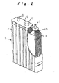
- a nickel-metal hydride rechargeable battery 1 includes positive electrode plates having nickel hydroxide as its active material, and negative electrode plates having hydrogen-absorption alloy.
- An electrode plate group 3 is formed by alternately stacking of the negative electrode plates and the positive electrode plates covered with pouch-shaped separators made of non-woven polypropylene fabric.
- the electrode plate group 3 is placed, together with an electrolyte, in a battery case 2 made of synthetic resin.
- An opening of the case 2 is closed with a lid 5 having a safety vent 4.
- Leads 6 are extended from an upper edge of each positive electrode plate on one side of the electrode plate group 3, and are connected to a positive electrode terminal 7 by resistance welding. In the same way, leads 6 are extended. from an upper edge of each negative electrode plate on the other side of the electrode plate group 3, and are connected to a negative electrode terminal 8 by resistance welding.
- the positive and negative electrode terminals 7 and 8 are attached to the lid 5.
- the positive electrode plate with a capacity of 1Ah and a reaction area per one side of 39.3cm 2 , was formed by filling a foamed nickel with a positive electrode material mainly comprising nickel hydroxide except an unfilled margin with a width of 5mm and attaching a nickel lead to the unfilled margin.
- the negative electrode plate with a capacity of 1.25Ah and a reaction area per one side of 39.3cm 2 , was formed by coating a punched metal with a negative electrode material mainly comprising hydrogen-absorption alloy of 20 ⁇ m in average particle diameter except an uncoated margin with a width of 5mm and attaching a nickel lead to the uncoated margin.
- the nickel-metal hydride rechargeable battery 1 was finally assembled by filling up the battery case 2 with 20g of an electrolyte mainly comprising potassium hydroxide, and then by sealing the case 2 with the lid 5.
- an initial charge was performed at a current of 1A for 5 hours, and then from the 2nd cycle the experiment was performed under condition of discharge at 1A for 4 hours and charge at 1A for 4 hours and 4 minutes. in these cycles, the absorbed hydrogen was used for the charge-discharge operations in the range of approximately 20-60% of the hydrogen-absorption capacity of the negative electrode alloy.
- the charge-discharge cycles were performed under the condition with a charge at 1A for 7 hours and discharge at 1A until discharge voltage became 1V.
- the absorbed hydrogen was used for the charge-discharge operations in the range of approximately 10-80% of the hydrogen-absorption capacity of the negative electrode alloy.
- Fig. 1 shows changes in capacity ratio for each battery. under a conventional working condition, the capacity ratio declined to 65% after 150 cycles. While in the embodiment of the invention, enough capacity was maintained even after 6000 cycles, and life characteristics were proved to have been remarkably improved. Even taking different values of discharge capacity per cycle, approximately 7Ah in the conventional example and approximately 4Ah in the example of the invention, into considerations, the total discharge capacity is proved to be larger in the present invention.
- the same batteries as that of the experiment 1 were fabricated using negative electrodes including hydrogen-absorption alloys having varied average particle diameters of 8, 10, 15, 20, 25, 30 and 35 ⁇ m. Then, the same life tests were performed and output power characteristics were determined as in the experiment 1.
- the output power measurements were performed at large current discharge after having adjusted each battery to have SOC60%.
- the output power expressed by watt (W) was defined as the product of each current (A), capable of flowing for 10 seconds or more until output voltage becomes 1V, and the voltage values of 1V.
- the measured values in test results in Table 1 show averages for 10 batteries.
- the nickel-metal hydride rechargeable battery of the invention cracks and corrosions in the hydrogen-absorption alloy of the negative electrode, which determines the life of the rechargeable battery, is prevented by limiting the charge and discharge operations to be. performed in the range of 20-60% of the hydrogen-absorption capacity of the hydrogen-absorption alloy; whereby the total quantity of electricity available for charge-discharge increases and the life characteristics as the rechargeable battery are improved so as to assure the battery provided with high reliability for a long time.
Landscapes
- Chemical & Material Sciences (AREA)
- Chemical Kinetics & Catalysis (AREA)
- Electrochemistry (AREA)
- General Chemical & Material Sciences (AREA)
- Engineering & Computer Science (AREA)
- Manufacturing & Machinery (AREA)
- Battery Electrode And Active Subsutance (AREA)
- Secondary Cells (AREA)
Abstract
Description
| Average particle diameter (µm) | Life (cycle) | Output power (W) |
| 8 | 1000 | 140 |
| 10 | 5000 | 140 |
| 15 | 5000 | 140 |
| 20 | 6000 or more | 130 |
| 25 | 6000 or more | 130 |
| 30 | 6000 or more | 120 |
| 35 | 6000 or more | 100 |
| Electrolyte quantity (g/Ah) | Life (cycle) | Output power (W) |
| 0.7 | 1000 | 80 |
| 1 | 5000 | 120 |
| 1.5 | 5000 | 130 |
| 2 | 6000 or more | 130 |
| 3 | 5000 | 130 |
| 3.5 | 4000 | 130 |
| Facing area (cm2/Ah) | Life (cycle) | Output power (W) |
| 40 | 2500 | 100 |
| 45 | 5000 | 130 |
| 55 | 6000 or more | 130 |
| 65 | 5000 | 140 |
| 70 | 3500 | 150 |
Claims (4)
- A nickel-metal hydride rechargeable battery comprising a positive electrode including nickel hydroxide;
a negative electrode including a hydrogen-absorption alloy; and
a separator interposed between the positive and negative electrodes;
characterized in that charge and discharge operations are performed in the range of 20-60% of hydrogen-absorption capacity of the hydrogen-absorption alloy. - The nickel-metal hydride rechargeable battery according to claim 1, wherein an average particle diameter of the hydrogen-absorption alloy is in the range of 10-25µm.
- The nickel-metal hydride rechargeable battery according to claim 1, wherein a quantity of an alkaline electrolyte per negative electrode capacity is in the range of 1.5-3g/Ah.
- The nickel-metal hydride rechargeable battery according to claim 1, wherein a facing area, per negative electrode capacity, between opposing negative and positive electrodes is in the range of 45-65cm2/Ah.
Applications Claiming Priority (2)
| Application Number | Priority Date | Filing Date | Title |
|---|---|---|---|
| JP2001109710 | 2001-04-09 | ||
| JP2001109710A JP4031620B2 (en) | 2001-04-09 | 2001-04-09 | Nickel metal hydride storage battery and method of using the same |
Publications (3)
| Publication Number | Publication Date |
|---|---|
| EP1249885A2 true EP1249885A2 (en) | 2002-10-16 |
| EP1249885A3 EP1249885A3 (en) | 2004-03-24 |
| EP1249885B1 EP1249885B1 (en) | 2010-05-12 |
Family
ID=18961613
Family Applications (1)
| Application Number | Title | Priority Date | Filing Date |
|---|---|---|---|
| EP02252501A Expired - Lifetime EP1249885B1 (en) | 2001-04-09 | 2002-04-08 | Nickel-metal hydride rechargeable battery |
Country Status (6)
| Country | Link |
|---|---|
| US (2) | US20020182496A1 (en) |
| EP (1) | EP1249885B1 (en) |
| JP (1) | JP4031620B2 (en) |
| KR (1) | KR100662158B1 (en) |
| CN (1) | CN1198353C (en) |
| DE (1) | DE60236338D1 (en) |
Cited By (2)
| Publication number | Priority date | Publication date | Assignee | Title |
|---|---|---|---|---|
| EP1458039A3 (en) * | 2003-03-10 | 2010-02-03 | Nissan Motor Co., Ltd. | Sealed nickel-metal hybride storage cells and hybrid electric vehicle having the storage cells |
| US8257862B2 (en) | 2005-09-21 | 2012-09-04 | Sanyo Electric Co., Ltd. | Alkaline storage battery |
Families Citing this family (12)
| Publication number | Priority date | Publication date | Assignee | Title |
|---|---|---|---|---|
| JP4573510B2 (en) * | 2003-09-30 | 2010-11-04 | 三洋電機株式会社 | Alkaline storage battery and battery pack |
| SE529144C2 (en) * | 2005-04-18 | 2007-05-15 | Sandvik Intellectual Property | Cut coated with composite oxide layer |
| JP4698291B2 (en) * | 2005-05-31 | 2011-06-08 | 三洋電機株式会社 | Alkaline storage battery |
| JP4849856B2 (en) * | 2005-09-27 | 2012-01-11 | 三洋電機株式会社 | Hydrogen storage alloy electrode, manufacturing method thereof, and alkaline storage battery |
| CN101477018B (en) * | 2008-12-30 | 2011-04-20 | 中国科学院上海微系统与信息技术研究所 | Full-automatic hydrogen storage material performance tester and its testing method |
| DE102010046647A1 (en) * | 2010-09-27 | 2012-03-29 | Hoppecke Batterie Systeme Gmbh | Nickel-metal hydride battery |
| WO2014050074A1 (en) * | 2012-09-25 | 2014-04-03 | 三洋電機株式会社 | Alkaline storage battery and storage battery system using same |
| JP5728520B2 (en) * | 2013-04-12 | 2015-06-03 | プライムアースEvエナジー株式会社 | Battery capacity recovery method, battery pack capacity recovery method, battery capacity recovery device, and battery pack capacity recovery device |
| JP6729033B2 (en) * | 2016-06-16 | 2020-07-22 | トヨタ自動車株式会社 | Battery system |
| CN106099233B (en) * | 2016-07-29 | 2018-12-14 | 昆明理工大学 | A method of lithium ion battery negative material is prepared using waste nickel hydrogen battery |
| USD906961S1 (en) * | 2019-01-31 | 2021-01-05 | Mitsubishi Electric Corporation | Servo amplifier |
| CN111916581A (en) * | 2019-05-09 | 2020-11-10 | 山东华太新能源电池有限公司 | High-capacity rechargeable nickel-metal hydride battery and manufacturing method thereof |
Family Cites Families (9)
| Publication number | Priority date | Publication date | Assignee | Title |
|---|---|---|---|---|
| US3366A (en) * | 1843-12-04 | Condensee of steam-engines | ||
| CN1079844A (en) | 1992-06-10 | 1993-12-22 | 北京广播通讯电源厂 | Nickel-Hydrogenized compound alkaline battery and manufacture method thereof |
| DE69333089T2 (en) * | 1992-09-14 | 2004-05-19 | Kabushiki Kaisha Toshiba, Kawasaki | Hydrogen-absorbing alloy for batteries, process for their production and nickel-metal hydride secondary battery |
| JP3825548B2 (en) * | 1997-11-28 | 2006-09-27 | 株式会社東芝 | Nickel metal hydride secondary battery |
| JP4010630B2 (en) * | 1998-03-09 | 2007-11-21 | 松下電器産業株式会社 | Hydrogen storage alloy electrode |
| JPH11269501A (en) * | 1998-03-20 | 1999-10-05 | Shin Etsu Chem Co Ltd | Method for producing hydrogen storage alloy powder and hydrogen storage alloy electrode |
| US6605375B2 (en) * | 2001-02-28 | 2003-08-12 | Ovonic Battery Company, Inc. | Method of activating hydrogen storage alloy electrode |
| US6589686B2 (en) * | 2001-02-28 | 2003-07-08 | Ovonic Battery Company, Inc. | Method of fuel cell activation |
| JP4126684B2 (en) | 2001-05-11 | 2008-07-30 | 松下電器産業株式会社 | Nickel metal hydride secondary battery |
-
2001
- 2001-04-09 JP JP2001109710A patent/JP4031620B2/en not_active Expired - Fee Related
-
2002
- 2002-04-08 US US10/117,190 patent/US20020182496A1/en not_active Abandoned
- 2002-04-08 EP EP02252501A patent/EP1249885B1/en not_active Expired - Lifetime
- 2002-04-08 DE DE60236338T patent/DE60236338D1/en not_active Expired - Lifetime
- 2002-04-09 KR KR1020020019114A patent/KR100662158B1/en not_active Expired - Lifetime
- 2002-04-09 CN CNB021058857A patent/CN1198353C/en not_active Expired - Lifetime
-
2004
- 2004-09-01 US US10/930,790 patent/US7560188B2/en not_active Expired - Lifetime
Cited By (2)
| Publication number | Priority date | Publication date | Assignee | Title |
|---|---|---|---|---|
| EP1458039A3 (en) * | 2003-03-10 | 2010-02-03 | Nissan Motor Co., Ltd. | Sealed nickel-metal hybride storage cells and hybrid electric vehicle having the storage cells |
| US8257862B2 (en) | 2005-09-21 | 2012-09-04 | Sanyo Electric Co., Ltd. | Alkaline storage battery |
Also Published As
| Publication number | Publication date |
|---|---|
| KR100662158B1 (en) | 2006-12-27 |
| KR20020079520A (en) | 2002-10-19 |
| EP1249885A3 (en) | 2004-03-24 |
| US20020182496A1 (en) | 2002-12-05 |
| JP2002313432A (en) | 2002-10-25 |
| DE60236338D1 (en) | 2010-06-24 |
| US7560188B2 (en) | 2009-07-14 |
| CN1380714A (en) | 2002-11-20 |
| JP4031620B2 (en) | 2008-01-09 |
| US20050026032A1 (en) | 2005-02-03 |
| EP1249885B1 (en) | 2010-05-12 |
| CN1198353C (en) | 2005-04-20 |
Similar Documents
| Publication | Publication Date | Title |
|---|---|---|
| EP1249885B1 (en) | Nickel-metal hydride rechargeable battery | |
| JPH09129213A (en) | Battery manufacturing method | |
| JP2002134161A (en) | Spiral electrode group for battery and battery | |
| US6649303B2 (en) | Alkaline storage battery with group of spiral electrodes | |
| EP0901179B1 (en) | Alkaline storage battery | |
| EP1256994B1 (en) | Alkaline rechargeable battery | |
| JP2792938B2 (en) | Hydrogen storage alloy electrode for alkaline storage batteries | |
| US6475671B1 (en) | Hydrogen absorbing alloy electrode and nickel-metal hydride battery | |
| JP3902330B2 (en) | Cylindrical battery | |
| JP2002343366A (en) | Electrode for alkaline storage battery and alkaline storage battery using the same | |
| JP3524744B2 (en) | Sealed alkaline storage battery | |
| JP3815511B2 (en) | Nickel / metal hydride sealed alkaline storage battery | |
| US20040258992A1 (en) | Negative plate for nickel/metal hydride secondary battery and fabrication method thereof | |
| JP3143109B2 (en) | Cylindrical sealed nickel storage battery | |
| WO2008085001A1 (en) | Negative plate for nickel/metal hydride secondary battery and fabrication method thereof | |
| JP3101622B2 (en) | Nickel-hydrogen alkaline storage battery | |
| JP2594147B2 (en) | Metal-hydrogen alkaline storage battery | |
| JP3266153B2 (en) | Manufacturing method of sealed alkaline storage battery | |
| JPH0642375B2 (en) | Metal-hydrogen alkaline battery | |
| JP2989300B2 (en) | Metal-hydrogen alkaline storage battery | |
| CN114824523A (en) | Method for manufacturing alkaline secondary battery | |
| CN114300759A (en) | Method for manufacturing nickel-metal hydride storage battery | |
| JPH07130369A (en) | Battery electrode | |
| JP2004327146A (en) | Alkaline storage battery | |
| JP2005026163A (en) | Cylindrical nickel-hydrogen storage battery and battery module using it |
Legal Events
| Date | Code | Title | Description |
|---|---|---|---|
| PUAI | Public reference made under article 153(3) epc to a published international application that has entered the european phase |
Free format text: ORIGINAL CODE: 0009012 |
|
| AK | Designated contracting states |
Kind code of ref document: A2 Designated state(s): AT BE CH CY DE DK ES FI FR GB GR IE IT LI LU MC NL PT SE TR |
|
| AX | Request for extension of the european patent |
Free format text: AL;LT;LV;MK;RO;SI |
|
| PUAL | Search report despatched |
Free format text: ORIGINAL CODE: 0009013 |
|
| AK | Designated contracting states |
Kind code of ref document: A3 Designated state(s): AT BE CH CY DE DK ES FI FR GB GR IE IT LI LU MC NL PT SE TR |
|
| AX | Request for extension of the european patent |
Extension state: AL LT LV MK RO SI |
|
| 17P | Request for examination filed |
Effective date: 20040913 |
|
| AKX | Designation fees paid |
Designated state(s): DE FR GB |
|
| 17Q | First examination report despatched |
Effective date: 20070927 |
|
| RAP1 | Party data changed (applicant data changed or rights of an application transferred) |
Owner name: PANASONIC CORPORATION Owner name: TOYOTA JIDOSHA KABUSHIKI KAISHA |
|
| GRAP | Despatch of communication of intention to grant a patent |
Free format text: ORIGINAL CODE: EPIDOSNIGR1 |
|
| GRAS | Grant fee paid |
Free format text: ORIGINAL CODE: EPIDOSNIGR3 |
|
| GRAA | (expected) grant |
Free format text: ORIGINAL CODE: 0009210 |
|
| AK | Designated contracting states |
Kind code of ref document: B1 Designated state(s): DE FR GB |
|
| REG | Reference to a national code |
Ref country code: GB Ref legal event code: FG4D |
|
| REF | Corresponds to: |
Ref document number: 60236338 Country of ref document: DE Date of ref document: 20100624 Kind code of ref document: P |
|
| PLBE | No opposition filed within time limit |
Free format text: ORIGINAL CODE: 0009261 |
|
| STAA | Information on the status of an ep patent application or granted ep patent |
Free format text: STATUS: NO OPPOSITION FILED WITHIN TIME LIMIT |
|
| 26N | No opposition filed |
Effective date: 20110215 |
|
| REG | Reference to a national code |
Ref country code: DE Ref legal event code: R097 Ref document number: 60236338 Country of ref document: DE Effective date: 20110214 |
|
| REG | Reference to a national code |
Ref country code: DE Ref legal event code: R084 Ref document number: 60236338 Country of ref document: DE |
|
| REG | Reference to a national code |
Ref country code: GB Ref legal event code: 746 Effective date: 20160120 |
|
| REG | Reference to a national code |
Ref country code: FR Ref legal event code: PLFP Year of fee payment: 15 |
|
| REG | Reference to a national code |
Ref country code: FR Ref legal event code: PLFP Year of fee payment: 16 |
|
| REG | Reference to a national code |
Ref country code: FR Ref legal event code: PLFP Year of fee payment: 17 |
|
| PGFP | Annual fee paid to national office [announced via postgrant information from national office to epo] |
Ref country code: FR Payment date: 20210309 Year of fee payment: 20 |
|
| PGFP | Annual fee paid to national office [announced via postgrant information from national office to epo] |
Ref country code: GB Payment date: 20210318 Year of fee payment: 20 |
|
| PGFP | Annual fee paid to national office [announced via postgrant information from national office to epo] |
Ref country code: DE Payment date: 20210316 Year of fee payment: 20 |
|
| REG | Reference to a national code |
Ref country code: DE Ref legal event code: R071 Ref document number: 60236338 Country of ref document: DE |
|
| REG | Reference to a national code |
Ref country code: GB Ref legal event code: PE20 Expiry date: 20220407 |
|
| PG25 | Lapsed in a contracting state [announced via postgrant information from national office to epo] |
Ref country code: GB Free format text: LAPSE BECAUSE OF EXPIRATION OF PROTECTION Effective date: 20220407 |